Table of Contents
Advertisement
22.8.2018
Arty A7 Reference Manual
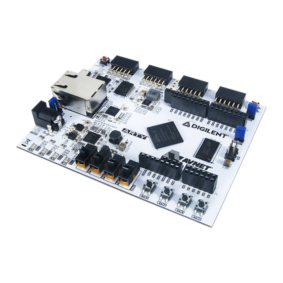
The Arty A7, formerly known as the Arty, is a ready-to-use development platform designed around the Artix-7™ Field Programmable
Gate Array (FPGA) from Xilinx. It was designed specifically for use as a MicroBlaze Soft Processing System. When used in this context,
the Arty A7 becomes the most flexible processing platform you could hope to add to your collection, capable of adapting to whatever
your project requires. Unlike other Single Board Computers, the Arty A7 isn't bound to a single set of processing peripherals: One
moment it's a communication powerhouse chock-full of UARTs, SPIs, IICs, and an Ethernet MAC, and the next it's a meticulous
timekeeper with a dozen 32-bit timers.
(https://reference.digilentinc.com/_media/reference/programmable-logic/arty/arty-4.png)
https://reference.digilentinc.com/reference/programmable-logic/arty-a7/reference-manual
Arty A7 Reference Manual [Reference.Digilentinc]
1/26
Advertisement
Table of Contents

Related Manuals for Xilinx Arty A7


Summary of Contents for Xilinx Arty A7
- Page 1 Gate Array (FPGA) from Xilinx. It was designed specifically for use as a MicroBlaze Soft Processing System. When used in this context, the Arty A7 becomes the most flexible processing platform you could hope to add to your collection, capable of adapting to whatever your project requires.
- Page 2 22.8.2018 Arty A7 Reference Manual [Reference.Digilentinc] https://reference.digilentinc.com/reference/programmable-logic/arty-a7/reference-manual 2/26...
- Page 3 22.8.2018 Arty A7 Reference Manual [Reference.Digilentinc] https://reference.digilentinc.com/reference/programmable-logic/arty-a7/reference-manual 3/26...
- Page 4 22.8.2018 Arty A7 Reference Manual [Reference.Digilentinc] https://reference.digilentinc.com/reference/programmable-logic/arty-a7/reference-manual 4/26...
- Page 5 22.8.2018 Arty A7 Reference Manual [Reference.Digilentinc] https://reference.digilentinc.com/reference/programmable-logic/arty-a7/reference-manual 5/26...
- Page 6 22.8.2018 Arty A7 Reference Manual [Reference.Digilentinc] https://reference.digilentinc.com/reference/programmable-logic/arty-a7/reference-manual 6/26...
- Page 7 22.8.2018 Arty A7 Reference Manual [Reference.Digilentinc] https://reference.digilentinc.com/reference/programmable-logic/arty-a7/reference-manual 7/26...
- Page 8 22.8.2018 Arty A7 Reference Manual [Reference.Digilentinc] https://reference.digilentinc.com/reference/programmable-logic/arty-a7/reference-manual 8/26...
- Page 9 22.8.2018 Arty A7 Reference Manual [Reference.Digilentinc] https://reference.digilentinc.com/reference/programmable-logic/arty-a7/reference-manual 9/26...
- Page 10 USB-UART Bridge Interaction and Sensory Devices 4 Switches 4 Buttons 1 Reset Button 4 LEDs 4 RGB LEDs Expansion Connectors 4 Pmod connectors Arduino/ChipKit Shield connector 1), 2), 3), 4) Arty A7-100 variant value in parentheses where different https://reference.digilentinc.com/reference/programmable-logic/arty-a7/reference-manual 10/26...
- Page 11 Arty A7 Reference Manual [Reference.Digilentinc] The Arty A7 is fully compatible with the high-performance Vivado ® Design Suite. It is supported under the free WebPACK™ license, so designs can be implemented at no additional cost. This free license includes the ability to create MicroBlaze™ soft-core processor designs.
- Page 12 1 Purchasing Options The Arty A7 can be purchased with either a XC7A35 or XC7A100 FPGA loaded. These two Arty A7 product variants are referred to as the Arty A7-35 and Arty A7-100, respectively. When Digilent documentation describes functionality that is common to both of these variants, they are referred to collectively as the “Arty A7”.
-
Page 13: Power Supplies
3 Power Supplies The Arty A7 requires a 5 volt power source to operate. This power source can come from the Digilent USB-JTAG port (J10) or it can be derived from a 7 to 15 Volt DC power supply that’s connected to the Power Jack (J13) or Pin 8 of Header J7. - Page 14 5V power source based on the supplies that are plugged into the board. If an external supply is connected to Power Jack J13, it will be used as the input source regardless of whether or not anything is plugged into the USB port (J10). If the Arty A7 is initially powered via USB and an external supply is plugged into J13, then the the 5V power source will automatically switch over to the regulated external supply rail and no brown-out will occur.
- Page 15 3.1 External Supply Voltage Monitoring The Arty A7 includes circuitry for monitoring the voltage of an external supply connected to Power Jack J13 or an external battery pack connected to Header J7. A voltage divider is used to scale the unregulated input voltage, VU, to be within the range (0-1V) that the on- chip 12-bit ADC () is capable of measuring.
- Page 16 3.3 5V Supply Power Monitoring The Arty A7 includes circuitry for monitoring the voltage of the 5 Volt supply as well as the current consumed from this supply. A voltage divider is used to scale the 5V input voltage to be within the range (0-1V) that the on-chip 12-bit ADC () is capable of measuring.
- Page 17 (port J10) or an external JTAG programmer, such as the Digilent JTAG-HS2, attached to port J8. You can perform JTAG programming any time after the Arty A7 has been powered on, regardless of whether the mode jumper (JP1) is set. If the FPGA is already configured, then the existing configuration is overwritten with the bitstream being transmitted over JTAG.
-
Page 18: Ethernet Phy
The MIG Wizard will require the fixed pin-out of the memory signals to be entered and validated before generating the IP core. For your convenience, an importable UCF file is provided on the Arty A7 Resource Center to speed up this process. It is included in the “MIG Project”... - Page 19 7 Oscillators/Clocks The Arty A7 includes a single 100 MHz () crystal oscillator connected to pin E3 (E3 is a MRCC input on bank 35). The input clock can drive MMCMs or PLLs to generate clocks of various frequencies and with known phase relationships that may be needed throughout a design.
- Page 20 9 Basic I/O The Arty A7 includes four tri-color LEDs, 4 switches, 4 push buttons, 4 individual LEDs, and a reset button, as shown in Figure 16. The push buttons and slide switches are connected to the FPGA via series resistors to prevent damage from inadvertent short circuits (a short circuit could occur if an FPGA pin assigned to a push button or slide switch was inadvertently defined as an output).
- Page 21 The Arty A7 has four Pmod connectors, some of which behave differently than others. Each Pmod connector falls into one of two categories: standard or high-speed. Table 4 specifies which category each Pmod falls into, and also lists the FPGA pins they are connected to.
- Page 22 11 Arduino/chipKIT Shield Connector The Arty A7 can be connected to standard Arduino and chipKIT shields to add extended functionality. Special care was taken while designing the Arty to make sure it is compatible with the majority of Arduino and chipKIT shields on the market. The shield connector has 49 pins connected to the FPGA for general purpose Digital I/O.
- Page 23 Power Input Connected in parallel with the external power supply connector (J13). See the “Power Supplies” section for information on powering the Arty A7 from this pin. 11.1 Shield Digital I/O The pins connected directly to the FPGA can be used as general purpose inputs or outputs. These pins include the I2C, SPI, and general purpose I/O pins.
- Page 24 Figure 11.2.1. This circuit allows the XADC module to accurately measure any voltage between 0V and 3.3V (relative to the Arty A7's GND ()) that is applied to any of these pins. If you wish to use the pins labeled A0-A5 as Digital inputs or outputs, they are also connected directly to the FPGA before the resistor divider circuit (also shown in Figure 11.2.1).
- Page 25 22.8.2018 Arty A7 Reference Manual [Reference.Digilentinc] First Name Last Name Email Address Submit Our Partners Help Customer Info Company Info Xilinx University Technical Support Videos About Us Program Forum (https://youtube.com/user/digilentinc) (https://store.digilentinc.com/ (https://store.digilentinc.com/partners/xilinx- (https://forum.digilentinc.com) pageid=26) Reference Wiki university-program/) (https://resource.digilentinc.com/verify/faq) Shipping & Returns Technology Partners (https://reference.digilentinc.com)
- Page 26 22.8.2018 Arty A7 Reference Manual [Reference.Digilentinc] (https://www.reddit.com/r/digilent) (https://www.linkedin.com/company/1454013) (https://www.flickr.com/photos/127815101@N07) https://reference.digilentinc.com/reference/programmable-logic/arty-a7/reference-manual 26/26...
Need help?
Do you have a question about the Arty A7 and is the answer not in the manual?
Questions and answers