Table of Contents
Advertisement
Quick Links
DS593 (v1.2.1) March 17, 2011
Features
•
High-performance FPGA and PROM programming and
configuration
•
Includes innovative FPGA-based acceleration
firmware encapsulated in a small form factor pod
attached to the cable
•
Leverages high-speed Slave Serial mode
programming interface
•
Recommended for prototyping use only
•
Easy to use
•
Fully integrated and optimized for use with Xilinx®
iMPACT software
•
Intuitive multiple cable management from a single
application
•
Supported on the following operating systems:
-
Microsoft Windows XP Professional
-
Microsoft Windows Vista
-
Red Hat Enterprise Linux
-
SUSE Linux Enterprise
•
Automatically senses and adapts to target I/O
voltage
•
Interfaces to devices operating at 5V (TTL), 3.3V
(LVCMOS), 2.5V, 1.8V and 1.5V
•
Intuitive flyleads-to-cable interface labeling
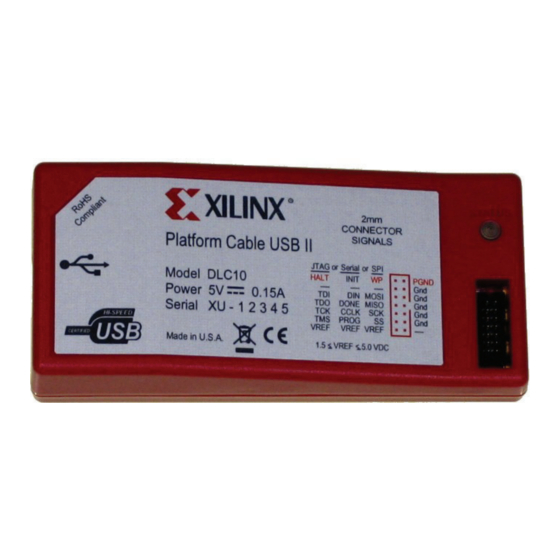
Platform Cable USB II Description
Much more than just a simple USB cable, Platform Cable
USB II
(Figure
1) provides integrated firmware (hardware
and software) to deliver high-performance, reliable and
easy-to-perform configuration of Xilinx devices.
Platform Cable USB II attaches to user hardware for the
purpose of configuring Xilinx FPGAs, programming Xilinx
PROMs and CPLDs, and directly programming third-party
SPI flash devices. In addition, the cable provides a means of
indirectly programming Platform Flash XL, third-party SPI
flash memory devices, and third-party parallel NOR flash
© Copyright 2008–2011 Xilinx, Inc. XILINX, the Xilinx logo, Virtex, Spartan, ISE, and other designated brands included herein are trademarks of Xilinx in the United States and
other countries. All other trademarks are the property of their respective owners.
DS593 (v1.2.1) March 17, 2011
35
www.xilinx.com
Platform Cable USB II
•
Reliable
•
Backwards compatibility with Platform Cable USB,
including Pb-Free (RoHS-compliant)
•
USB Integrators Forum (USB-IF) certified
•
CE and FCC compliant
•
Leverages industry standards, including JTAG
Boundary-Scan IEEE 1149.1, SPI and USB 2.0
•
Programs and configures all Xilinx devices
•
XC18V00 ISP PROMs
•
Platform Flash XCF00S/XCF00P/XL PROMs
•
All Virtex®, Spartan® and XC4000 FPGA families
•
XC9500 / XC9500XL / XC9500XV and
CoolRunner™ XPLA3 / CoolRunner-II CPLDs
Note:
Xilinx iMPACT software is required for
programming and configuration
•
Third-party PROM device programming support
•
Directly programs selected Serial Peripheral
Interface (SPI) flash memory devices
•
Indirectly programs selected SPI or parallel flash
memory devices via FPGA JTAG port
•
Highly optimized for use with Xilinx design tools
•
ISE® Foundation™ Software
•
Embedded Development Kit
•
ChipScope™ Pro Analyzer
•
System Generator for DSP
memory devices via the FPGA JTAG port. Furthermore,
Platform Cable USB II is a cost effective tool for debugging
embedded software and firmware when used with
applications such as Xilinx's Embedded Development Kit
and ChipScope Pro Analyzer.
Platform Cable USB II is an upgrade to and replaces
Platform Cable USB. Similar to its popular predecessor,
Platform Cable USB II is intended for prototyping
environments only. Platform Cable USB II is backwards
PN 0011051 04
1
Advertisement
Table of Contents

Subscribe to Our Youtube Channel
Related Manuals for Xilinx Platform Cable USB II


Summary of Contents for Xilinx Platform Cable USB II
- Page 1 NOR flash © Copyright 2008–2011 Xilinx, Inc. XILINX, the Xilinx logo, Virtex, Spartan, ISE, and other designated brands included herein are trademarks of Xilinx in the United States and other countries. All other trademarks are the property of their respective owners.
- Page 2 Compatible with Platform Cable USB and is supported by all Xilinx design tools that support Platform Cable USB. Platform Cable USB II attaches to the USB port on a desktop or laptop PC using an off-the-shelf Hi-Speed USB A–B cable.
- Page 3 PCMCIA card. Platform Cable USB II is designed to take full advantage of the bandwidth of USB 2.0 ports, but it is also backward- compatible with USB 1.1 ports. Refer to...
- Page 4 Operating Power Platform Cable USB II is a bus-powered device (drawing less than 150 mA from the host USB port under all operating conditions), automatically adapting to the capabilities of the host USB port to achieve the highest possible performance.
- Page 5 Hot Plug and Play Platform Cable USB II can be attached and removed from the host computer without the need to power-down or reboot. There is a momentary delay after connecting the cable to an available port before the status LED illuminates — this process is called enumeration.
- Page 6 DS593_04_021408 Figure 4: iMPACT (9.2i) Output Pull-Down Menu Option 2: Manual Cable Connect To manually connect the cable, select Output → Cable Setup. Select the Xilinx USB Cable radio button in the Cable Communication Setup dialog box (Figure X-Ref Target - Figure 5 DS593_05_021408 Figure 5: iMPACT (10.1) Cable Communication Setup...
- Page 7 Multiple USB Cable Management Platform Cable USB II contains a 64-bit electronic serial number used by applications to uniquely identify and access a specific USB cable when multiple USB cables (up to 127) are connected to the same host. iMPACT provides a dialog box (Figure 6, page 7) allowing users to select a specific cable from a list of attached cables.
- Page 8 BSDL file for maximum JTAG TCK specifications. Note: Certain Xilinx design tools and iMPACT versions earlier than 7.1i do not restrict the TCK_CCLK_SCK selections in JTAG mode. Accordingly, users should take care to select a TCK_CCLK_SCK frequency matching the JTAG TCK specifications for the slowest device in the target chain.
- Page 9 7) provides information about cable operating conditions. For example, if the host port is USB 2.0, Platform Cable USB II connects at Hi-Speed and the status bar shows usb-hs. If the host port is USB 1.1, Platform Cable USB II connects at full-speed, and the status bar shows usb-fs. Finally, the status bar displays the active cable and TCK_CCLK_SCK frequency.
- Page 10 Platform Cable USB II The status LED is off whenever Platform Cable USB II enters a suspend state (see System Suspend, page 11), is disconnected from a USB port, or is connected to an un-powered USB port. Table 4 summarizes the various status LED states.
- Page 11 Note: This feature is not supported in earlier versions of iMPACT, while iMPACT is operating in batch mode, or by other Xilinx design tools. In these cases, it is recommended that suspend be disabled in the host system when performing long, continuous operations.
- Page 12 12). The connector on the bottom side of the adapter mates with the 14-pin Platform Cable USB II male 2-mm connector. A 7-pin right-angle header on the top side of the adapter mates with the standard Xilinx flying wire set.
- Page 13 DS593_12_012508 Figure 12: Flying Wire Adapter (Side) without Wires Physical Connection to the Host Each Platform Cable USB II includes a detachable, Hi-Speed-USB-certified, 1.8-meter A–B cable (Figure 13). Under no circumstances should user-supplied cables exceed 5 meters. Sub-channel cables (intended for low-speed 1.5 Mb/s signaling) should not be used with Platform Cable USB II.
- Page 14 2475-14G2 2422-14G2 2401R-G2-14 www.commcon.com Notes: Some manufacturer pin assignments do not conform to Xilinx pin assignments. Please refer to the manufacturer’s data sheet for more information. Additional ribbon cables can be purchased separately from the Xilinx Online Store. DS593 (v1.2.1) March 17, 2011...
- Page 15 JTAG chain. When PGND is high-Z, the primary configuration source drives the JTAG chain. This capability allows Platform Cable USB II to remain attached to the target system while remaining isolated from the primary configuration source. A similar scheme can be used with Slave Serial topologies.
- Page 16 CCAUX Pin 13 is grounded on legacy Xilinx USB cables (models DLC9, DLC9G and DLC9LP), and Parallel Cable IV (model DLC7). These cables need to be manually detached from the 2-mm connector to allow the primary configuration source to have access to the JTAG chain.
- Page 17 Platform Cable USB II can connect directly to a single SPI flash device. Figure 18, page 18 shows an example SPI flash connection. XAPP951, Configuring Xilinx FPGAs with SPI Serial Flash provides additional details of the cable connections necessary to program a FPGA bitstream into a SPI flash device. Note: See Configuring Xilinx FPGAs with SPI Serial Flash for a list of supported SPI devices.
- Page 18 Typically, an FPGA and other slave SPI devices (not shown) are connected to the SPI bus. The other devices on the SPI bus must be disabled when the cable is connected to the 2-mm connector to avoid signal contention. When a Xilinx FPGA is connected to the SPI bus, the cable holds the FPGA PROG_B pin Low to insure the FPGA SPI pins are 3-stated.
- Page 19 No damage to Platform Cable USB II occurs if the A–B cable is unplugged from the host while the ribbon cable or flying leads are attached to a powered target system. Similarly, no damage to target systems occurs if Platform Cable USB II is powered and attached to the target system while the target system power is off.
- Page 20 Platform Cable USB II X-Ref Target - Figure 19 DS593_19_021408 Figure 19: V Current vs. V Voltage X-Ref Target - Figure 20 REF_CLAMP FPGA NC7SZ126 REF_CLAMP 2-mm Connector 30.1Ω Output I/O Pin BAT54 High-Z Control To input buffer DS593_20_021408 Figure 20: Target Interface Driver Topology DS593 (v1.2.1) March 17, 2011...
- Page 21 Platform Cable USB II X-Ref Target - Figure 21 Voltage (VDC) DS593_21_021408 Figure 21: Output Drive Voltage vs. V Input Receive Structure Each input signal is routed through a NC7WZ07 ultra high-speed CMOS, open-drain receive buffer. Series-termination resistors (499Ω) provide current limit protection for positive and negative excursions. Schottky diodes provide the input buffers with undershoot protection.
- Page 22 (iMPACT default) or when the cable is in Slave Serial or SPI modes. Note: HALT signal control is available in iMPACT 9.2i and later. HALT remains high-Z in earlier versions of iMPACT and in Xilinx design tools where the HALT signal is not supported.
- Page 23 Platform Cable USB II X-Ref Target - Figure 24 DS593_24_021408 Figure 24: Enabling the HALT Signal in iMPACT (9.2i) Timing Specifications For JTAG, SPI, and Slave Serial configuration modes, the TDI_DIN_MOSI and TMS_PROG_SS outputs change on falling edges of TCK_CCLK_SCK (Figure 25).
- Page 24 Platform Cable USB II Note: The propagation delay from TCK to TDO is 26 ns. Because Figure 26 shows a propagation delay of 37 ns, the difference of 11 ns is attributable exclusively to input delays in the cable. At 12 MHz, there is still sufficient setup time before the cable samples prior to the next negative TCK transition.
- Page 25 Platform Cable USB II X-Ref Target - Figure 26 Negative TCK transition at G1 causes target device to change TDO state, which propagates to the cable at G2 in less than ½ clock cycle in this 12-MHz example. DS593_26_021408 Figure 26: TDO Sampling Example at 12 MHz (TDO Propagation Delay) DS593 (v1.2.1) March 17, 2011...
- Page 26 Platform Cable USB II X-Ref Target - Figure 27 TDO setup time prior to internal sampling clock (G2 – G1) is 42ns in this 12-MHz example. DS593_27_011508 Figure 27: TDO Sampling Example at 12 MHz (TDO Setup Time Relative to Sampling Point) DS593 (v1.2.1) March 17, 2011...
- Page 27 Figure 28: TDO Sampling Example at 12 MHz (Analog Signals on Target System) Signal Integrity Platform Cable USB II uses high-slew-rate buffers to drive its output pins. Each buffer has a 30.1Ω series termination resistor. Users should pay close attention to PCB layout to avoid transmission line effects. Visit the...
- Page 28 30C). When no external power source is present, these hubs draw their power from their upstream USB port. If Platform Cable USB II is connected to such a hub while operating at USB 1.1 speeds, the cable enumerates as a full- speed device.
- Page 29 Cable may to slow bus speed not enumerate. DS593_30_021408 Figure 30: Platform Cable USB II Performance with Various Hub Types Interface Pin Descriptions Table 6: JTAG/SPI/Slave Serial Port: 2-mm Connector Signals MODE Direction Description...
- Page 30 Platform Cable USB II Table 6: JTAG/SPI/Slave Serial Port: 2-mm Connector Signals (Cont’d) MODE Direction Description JTAG Slave-Serial Number Configuration Programming Configuration JTAG Test Data In. This pin outputs the – – serial data stream transmitted to the TDI pin on the first device in a JTAG chain.
- Page 31 Slave-Serial Number Configuration Programming Configuration Slave Serial Configuration Done. This pin indicates to Platform Cable USB II that target FPGAs have received the entire configuration bitstream and should be – – Done connected to the Done pin on all FPGAs in parallel for daisy-chained configurations.
- Page 32 Platform Cable USB II Table 7: Absolute Maximum Ratings Symbol Description Conditions Value Units DC Output Current (TCK_CCLK_SCK, ± TMS_PROG_SS, TDI_DIN_MOSI, and INIT) Notes: Exposure to absolute rating conditions for extended periods of time can affect product reliability. The values listed in this table are stress ratings only.
- Page 33 All times are in nanoseconds and are relative to the target system interface connector. Min is the minimum setup time guaranteed by Platform Cable USB II relative to the positive edge of TCK_CCLK_SCK. Min is the minimum setup required by Platform Cable USB II to properly sample TDO_DONE_MISO.
- Page 34 Industry Canada Information This Class A digital apparatus complies with Canadian ICES-003. Ordering Information Platform Cable USB II ships with each of the items shown in Table 11 plus a 1.8-meter, Hi-Speed USB, A-B cable. Table 11: Ordering Information...
- Page 35 Converted document to latest template containing current Xilinx logos and colors. Notice of Disclaimer THE XILINX HARDWARE FPGA AND CPLD DEVICES REFERRED TO HEREIN (“PRODUCTS”) ARE SUBJECT TO THE TERMS AND CONDITIONS OF THE XILINX LIMITED WARRANTY WHICH CAN BE VIEWED AT http://www.xilinx.com/warranty.htm. THIS LIMITED WARRANTY DOES NOT EXTEND TO ANY USE OF PRODUCTS IN AN APPLICATION OR ENVIRONMENT THAT IS NOT WITHIN THE SPECIFICATIONS STATED IN THE XILINX DATA SHEET.
Need help?
Do you have a question about the Platform Cable USB II and is the answer not in the manual?
Questions and answers