
Subscribe to Our Youtube Channel
Related Manuals for Hypertherm HyPrecision Predictive P-15


Summary of Contents for Hypertherm HyPrecision Predictive P-15
- Page 1 HyPrecision Predictive™ Waterjet Pumps P-15 / P-30 / P-50 / P-50S / P-60S / P-75S Operator Manual 810120 | Revision 0 | English...
- Page 2 One of Hypertherm's long-standing core values is a focus on minimizing our impact on the environment. Doing so is critical to our, and our customers', success. We are always striving to become better environmental stewards; it is a process we care deeply about.
- Page 3 HyPrecision Predictive™ Waterjet Pumps P-15 / P-30 / P-50 / P-50S / P-60S / P-75S Operator Manual 810120 Revision 0 English Original Instructions October 2018 Hypertherm, Inc. Hanover, NH 03755 USA...
- Page 4 HTIndia.info@hypertherm.com (Main Office Email) TechSupportAPAC@hypertherm.com (Technical Service Email) Hypertherm products are designed and manufactured with a commitment to continuous quality control and safety. Contact a Hypertherm Technical Service Associate for information and support regarding the installation, operation, maintenance, and repair of this equipment.
-
Page 5: Table Of Contents
Declaration of conformity ..........................SC-16 Differences in national standards ........................SC-17 Higher-level systems ............................SC-17 Environmental stewardship ....................SC-19 Hypertherm products: waste and recycling ....................SC-19 Chemical handling and usage .......................... SC-19 Particle emission and waste water quality ....................SC-19 Safety ............................SC-21 User qualification and training .......................... - Page 6 Contents Turn on the utilities ..............................56 Use the controls ................................57 Operation panel ..................................57 Operator interface: Operation screens ..........................58 Operate the pump remotely ............................60 Operate the pump locally ............................61 Operate the pump ..................................65 Stop the pump ................................67 Emergency ....................................67 Typical .......................................67 5 Preventive maintenance ......................
- Page 7 Contents Assemble the intensifier ..............................108 High-pressure water system: Bleed-down valve ....................122 Remove the bleed-down valve from the pump ......................122 Disassemble the bleed-down valve ..........................123 Assemble the bleed-down valve ............................124 Install the bleed-down valve ..............................125 Start the pump after maintenance ........................126 Operator interface: Maintenance screens ......................
- Page 8 Contents Pressure ....................................166 Leaks ...................................... 168 Seal Maintenance Indicator (SMI) ........................171 Operator interface ................................172 A warning or a fault occurs during the start sequence ................... 174 The pump makes noise during operation ......................174 Controller problems ..............................175 Input/output status ................................
- Page 9 Contents Connect the electrical power ............................208 Do the first start ................................ 209 Do a preoperation inspection ............................209 Turn on the utilities ................................209 Make sure that the primary motor turns in the correct direction ................210 Make sure that the heat exchanger fan motor turns in the correct direction ............212 Turn on the pump .................................213 Adjust the external boost pump pressure ........................213 Measure the air pressure in the water accumulator tank ....................214...
- Page 10 Contents HyPrecision Predictive waterjet pump Operator Manual 810120...
-
Page 11: Pump Information
Pump information Model Serial number The serial number is on the data plate, which is found on the utility panel on the back of the pump. System schematic drawing number The system schematic drawing number is found in the electrical enclosure door on a green label. Purchase date Distributor Installation date... - Page 12 Pump information HyPrecision Predictive waterjet pump...
-
Page 13: Warranty
the result of the system being operated contrary to Hypertherm’s instructions or stated limits of rated and normal use. For information about the manufacturer’s warranty, refer to the conditions of sale provided when the product was purchased. -
Page 14: Disclaimer
Warranty Disclaimer All product information contained in this manual is believed to be reliable as of the date of publishing the manual. The content is subject to change without notice. Content in the manual could contain technical inaccuracies or typographical errors and could be changed or updated without notice. SC-14 Safety and compliance... -
Page 15: Product Stewardship
European directives and standards. Only those versions of Hypertherm products with a CE mark on or near the data plate have been tested for compliance with the applicable European directives, such as the Low Voltage Directive, the Electromagnetic Compatibility Directive, and the Machinery Directive. -
Page 16: Declaration Of Conformity
Product stewardship Declaration of conformity SC-16 Safety and compliance... -
Page 17: Differences In National Standards
CE mark on the data plate. Countries where the CE mark in necessary or that have compulsory electromagnetic compatibility regulations must use CE versions of Hypertherm products with the CE mark on the data plate. These could include: ... - Page 18 Product stewardship SC-18 HyPrecision Predictive waterjet pump...
-
Page 19: Environmental Stewardship
Particle emission and waste water quality Hypertherm does not manufacture or supply the materials that are cut and has no knowledge whether the particles released from materials that are cut can pose a physical danger or health risk. Get advice from with your supplier or other technical advisor for guidance concerning the properties of the material you cut with a Hypertherm product. - Page 20 Environmental stewardship SC-20 Safety and compliance...
-
Page 21: Safety
Operator Manual (OM) These navigation instructions can change without notice. The safety precautions in this manual are general and can not anticipate every situation. Hypertherm, Inc. acknowledges that unforeseen situations such as equipment failure, site variability, insufficient maintenance, failure of control equipment, and other events can cause equipment damage, injuries, or death. It is the user’s responsibility to identify dangers and to take the steps necessary to minimize risks. -
Page 22: User Qualification And Training
Safety User qualification and training All users must read and understand these instructions before installing, operating, or doing maintenance on this equipment. Do not let an untrained person to operate this equipment. Operators must be approved to operate and maintain this equipment. -
Page 23: Symbols And Marks
Symbols and marks Information and symbols Some symbols in this table could apply to other products. This symbol identifies an imminently dangerous condition or a situation that will cause serious injuries or death if ignored. DANGER ANGEROUS VOLTAGE RISK OF SHOCK DANGER A waterjet is a cutting tool. -
Page 24: Symbols And Marks Found On The Equipment
Symbols and marks This symbol identifies tools or materials that are necessary or recommended for a procedure. This symbol identifies information that could cause the user to fail at the task if ignored. This symbol identifies a tip or helpful information. Symbols and marks found on the equipment Some symbols or marks in this table could apply to other products. - Page 25 European directives and standards. Only those versions of Hypertherm products with a CE mark on or near the data plate have been tested for compliance with the applicable European directives, such as the Low Voltage Directive, the Electromagnetic Compatibility Directive, and the Machinery Directive.
-
Page 26: Measurements
Symbols and marks OOLING IN Water-cooled system: Low-pressure supply water or water from a chiller that goes to a heat exchanger Air-cooled system: Hydraulic fluid from an external heat exchanger OOLING OUT Water-cooled system: Low-pressure water from the heat exchanger that goes to a drain or goes to a chiller Air-cooled system: Hydraulic fluid that is sent to an external heat exchanger Cut pressure... -
Page 27: Terminology
Section 1 Terminology In this section This section includes definitions for terms used in this and other HyPrecision manuals. Some terms could be applicable to other products. HyPrecision Predictive waterjet pump Operator Manual 810120... - Page 28 1 – Terminology air cooled The system uses hydraulic fluid and an external heat exchanger to keep the pump cool attenuator A pressure vessel that compensates for pressure fluctuations and maintains a consistent output water pressure American Wire Gauge, a standardized wire gauge system that is used in North America A unit of pressure: 1 bar equals 100 kPa or 14.5 psi or 100,000 N/m British thermal unit, a standard unit of energy equal to approximately 1,055 joules or 1,055 watt-seconds Used in the United States and sometimes in the United Kingdom, the Btu measures the energy necessary to...
- Page 29 1 – Terminology energy-isolating device A mechanical device that physically prevents the transmission or release of energy Examples include a manually operated circuit breaker, a disconnect switch, or an equivalent device that blocks or isolates energy Selector switches, emergency stop knobs, and other circuit control devices are not energy-isolating devices. Extreme pressure, a property of some types of grease;...
- Page 30 1 – Terminology impact wrench Also known as an impact gun, air wrench, air gun, or rattle gun; a powered tool that supplies high torque to turn a socket inrush current Also known as input surge current or switch-on surge; the maximum instantaneous current that a motor uses when it is first turned on International Organization for Standardization, an independent membership organization that develops voluntary industrial standards...
- Page 31 1 – Terminology NFPA 70E ® The Standard for Electrical Safety in the Workplace , is a standard that contains requirements for safe work ® practices to protect personnel from electrical dangers ® The National Electrical Code ® is the United States codes and standards for electrical design, installation, and inspection NLGI grade National Lubrication Grease Institute, also known as a consistency number;...
- Page 32 1 – Terminology pipe A rigid, hollow cylinder that is used to move fluids; pipes are not always one piece from end to end; fittings include adapters, tees, and reducers; pipes have a pressure rating Pipe is sized by wall thickness (schedule) and a standardized outer diameter (OD). The OD in millimeters is called nominal diameter (DN) and in inches it is called nominal pipe size (NPS).
- Page 33 1 – Terminology static seal The high-pressure seal at the output end of the high-pressure cylinder; the static seal does not touch the plunger Refer to dynamic seal supply water Water going to the pump from a water softener, a reverse osmosis system, a well, or a public utility system integrator An integrator of waterjet cutting systems that are sold directly to end users technical drawings...
- Page 34 1 – Terminology WASTE WATER OUT Water from the bleed-down valve or the low-pressure system that goes to a drain water cooled The system uses low-pressure water and an internal heat exchanger to keep the pump cool weep hole A small hole in a high-pressure component that lets leaking water drain HyPrecision Predictive waterjet pump Operator Manual 810120...
-
Page 35: Product Description
Section 2 Product description In this section Flow diagrams for water and hydraulic fluid Descriptions of the system and major components in the pump Images in this manual are for reference purposes. It is possible that your product is not shown accurately. -
Page 36: Flow Of Water And Hydraulic Fluid
2 – Product description Flow of water and hydraulic fluid These diagrams show a typical installation. Low-pressure water High-pressure water Seal Maintenance Technology™ Utility panel: C Attenuator UTTING WATER IN Supply water from a water softener, a reverse Utility panel: C UTTING WATER OUT osmosis system, a well, or a public utility goes into High-pressure water goes from the intensifier to... -
Page 37: Cooling Loop
2 – Product description Cooling loop Compressing hydraulic fluid generates substantial heat that can cause damage to equipment and decrease the life of the fluid. Fluid that is too hot is thin, which accelerates wear on the parts, increases the formation of sludge, degrades the fluid, and decreases its lubrication and protective qualities. - Page 38 2 – Product description Cooling loop for an air-cooled system (external heat exchanger) Hydraulic fluid tank Utility panel: C OOLING OUT Hydraulic fluid goes from the tank to the gear External heat exchanger pump. A fan keeps the hydraulic fluid cool. Gear pump Utility panel: C OOLING IN...
-
Page 39: Pump Exterior
2 – Product description Pump exterior Front view Front panel Electrical enclosure Gauge panel Operator interface Seal Maintenance Indicator (SMI) Operation panel Beacon light Dirty water container Panels The front, rear, and side panels have locks to prevent access to system components during operation. Open the locks with a standard screwdriver. - Page 40 2 – Product description Seal Maintenance Indicator (SMI) Seal Maintenance Technology™ optimizes seal life. When an intensifier seal begins wearing out, water and hydraulic fluid leak from the weep holes in the high-pressure ends. A drip tray, which is attached to the bottom of each side of the intensifier, collects fluid leaking from weep holes. From the drip tray, fluid flows through a clear tube to the SMI.
- Page 41 2 – Product description Electrical enclosure Motor starters, thermal overload relays, and breakers are in the enclosure. The primary breaker disconnect lever is on the electrical enclosure. Primary breaker disconnect lever Operator interface On the operator interface, a series of screens shows equipment status and lets the operator control the pump and the intensifier.
- Page 42 2 – Product description Operation panel The operation panel turns the control circuit in the pump on and off and controls local and remote pump operation. button EMERGENCY STOP button ONTROLS key switch indicator light OCAL EMOTE EMOTE Refer to on page 58 for information.
- Page 43 2 – Product description Rear view Utility panel The air and water fittings are found on the utility panel. HyPrecision P-15/P-30/P-50 pump HyPrecision P-50S/P-60S/P-75S pump OMPRESSED AIR IN UTTING WATER OUT Compressed air operates the This tubing carries high-pressure bleed-down valve. water from the pump to the cutting table.
- Page 44 2 – Product description Top deck Top cover A hinged top cover protects components on the top deck from dirt and debris. Open the lock with a standard screwdriver. HyPrecision P-50S/P-60S/P-75S pumps have a top cover with transparent panels. An optional top cover is available for HyPrecision P-15/P-30/P-50 pumps. Electrical interlock (optional on all models with top covers) The electrical interlock is part of the emergency stop circuit.
- Page 45 2 – Product description Intensifier Bleed-down valve Attenuator Intensifier Low-pressure supply water goes into the intensifier, where it is pressurized for piercing and cutting. The hydraulic center section contains hydraulic fluid, which is used to compress water in the high-pressure ends. High-pressure end Hydraulic center section The pressurized water exits the high-pressure end through a check valve and goes to the attenuator.
-
Page 46: Pump Interior
2 – Product description Pump interior Front view Water accumulator tank Primary motor Water filters Water accumulator tank This is a closed water chamber with a pressurized air bladder. It evens out low-pressure water flow to the intensifier, and maintains a consistent output water pressure. Water filters Water filters remove impurities from the supply water before it goes to the intensifier. - Page 47 2 – Product description Primary motor Proportional control valve Hydraulic pump Gear pump Primary motor Hydraulic manifold Proportional control valve Electronic proportional pressure control is a closed-loop monitoring system. It adjusts pressure when changes are sensed, such as when the operator enters a water pressure target change on the operator interface pump or at the CNC.
- Page 48 2 – Product description Rear view Hydraulic fluid tank Hydraulic fluid filter Boost pump Water manifold HyPrecision Predictive waterjet pump Operator Manual 810120...
- Page 49 2 – Product description Hydraulic fluid tank HyPrecision P-15/P-30/P-50 pump HyPrecision P-50S/P-60S/P-75S pump Filler-breather cap Drain valve Sight gauge Suction strainer The filler-breather cap keeps airborne contamination out of the tank and prevents pressure from building up in the tank. It also gives access to the tank for adding hydraulic fluid. A temperature sensor and a level sensor in the tank monitor the hydraulic fluid.
- Page 50 2 – Product description Hydraulic fluid filter This filter removes contamination from the hydraulic fluid. Water manifold Boost pump pressure regulator Bleed-down valve solenoid Supply cutting water solenoid Low water-pressure water dump valve Low-pressure transducer Low-pressure water relief valve Boost pump pressure regulator This knob lets the user adjust boost pump pressure.
-
Page 51: Optional Equipment
Section 3 Optional equipment These optional items are available for HyPrecision Predictive waterjet pumps. All HyPrecision pump models External heat exchanger Standard pumps have a water-cooled heat exchanger. In an air-cooled system, the temperature sensor in the hydraulic fluid tank turns on an external heat exchanger. Electrical interlock An electrical interlock on the top cover prevents access to the components on the top deck while the system is pressurized. - Page 52 3 – Optional equipment HyPrecision Predictive waterjet pump Operator Manual 810120...
-
Page 53: Operation
Section 4 Operation In this section Safety Do a preoperation inspection Turn on the utilities Use the controls Operation panel Operator interface: Operation screens Operate the pump remotely Operate the pump locally ... -
Page 54: Safety
4 – Operation Safety Refer to the instruction manual. Read and understand all of the safety guidelines in this manual. A waterjet is a cutting tool. Keep away from high-pressure streams and leaks. Pressurized fluid can cause injuries. A high-pressure injection injury is a surgical emergency. Get medical treatment immediately for all high-pressure waterjet injuries. - Page 55 4 – Operation This waterjet equipment could make more noise than is permitted by national or local codes. When this intensifier is operating, the noise level is 75 dB(A) to 80 dB(A). Water flow rate, pipe layout, and the acoustical characteristics of the building have an effect on noise level. Long periods of exposure to noise can cause permanent hearing loss.
-
Page 56: Do A Preoperation Inspection
4 – Operation Do a preoperation inspection Make sure that all connections, fasteners, locking devices, hoses, and fittings are tight. WARNING Look for leaks, deterioration, damage, or other conditions that can interfere with operation. Look at the sight gauge on the hydraulic fluid tank. Add hydraulic fluid, if necessary. ... -
Page 57: Use The Controls
4 – Operation Use the controls Operation panel The operation panel turns the control circuit in the pump on and off and controls local and remote pump operation. EMERGENCY STOP ONTROLS This turns on the control circuit in The button turns off the control the pump. -
Page 58: Operator Interface: Operation Screens
4 – Operation Operator interface: Operation screens The operation screen on the operator interface lets the user: turn the pump on or off. set or change the water pressure. select the operating mode (cut or pierce). monitor the status of the intensifier. - Page 59 4 – Operation Intensifier status indicator and stroke indicators Intensifier status Intensifier stroke rate to the right Intensifier stroke rate to the left The intensifier status can be enabled (green) or not enabled (red). The bars show the intensifier’s stroke rate. ...
-
Page 60: Operate The Pump Remotely
4 – Operation Operate the pump remotely Turn on the pump The pump is on when the primary motor is operating. The primary motor drives 2 pumps. A hydraulic pump moves hydraulic fluid to the intensifier. A gear pump moves hydraulic fluid through the cooling loop. -
Page 61: Operate The Pump Locally
4 – Operation Operate the pump locally Turn on the pump The pump is on when the primary motor is operating. The primary motor drives 2 pumps. A hydraulic pump moves hydraulic fluid to the intensifier. A gear pump moves hydraulic fluid through the cooling loop. - Page 62 4 – Operation 6. The timer expires. If the supply water pressure is not at the water manifold pressure setpoint after 20 seconds: • The start sequence stops. • A Low Supply Water Pressure alarm shows on the screen. • The beacon light flashes red.
- Page 63 4 – Operation 4. The timer expires. If the time between intensifier strokes is longer than the Intensifier timer setpoint, pressure in the system is sufficient. The timer is set at 1.5 seconds by default. If the time between intensifier strokes is shorter than the Intensifier timer, pressure in the system is too low. A Start Warning: Hydraulics alarm shows on the screen.
- Page 64 4 – Operation Stage 5: Increase the pressure to the cut pressure setpoint 1. The hydraulic pressure increases. 2. The Cut timer starts. The timer is set at 5 seconds by default. 3. The intensifier strokes to increase water pressure in the system. 4.
-
Page 65: Operate The Pump
4 – Operation Operate the pump Run mode Set the water pressure target 1. On the operator interface, touch these symbols to select pierce-pressure mode or cut-pressure mode. Pierce-pressure mode (shown on) Cut-pressure mode 2. There are 2 ways to change the water pressure target on the operator interface. a. - Page 66 4 – Operation c. Type the number and touch Enter. Pierce pressure is typically lower than 1,380 bar (138,000 kPa / 20,000 psi). The minimum water pressure target is 345 bar (34,500 kPa / 5,000 psi). If the water pressure is set to a lower value, the pump operates at the minimum setpoint.
-
Page 67: Stop The Pump
4 – Operation Stop the pump Emergency The EMERGENCY STOP button does not disconnect main electrical power from the machine. WARNING The electrical interlock is part of the emergency stop circuit. If the top cover is opened while the pump is on, the result is the same as pushing the EMERGENCY STOP button. - Page 68 4 – Operation HyPrecision Predictive waterjet pump Operator Manual 810120...
-
Page 69: Preventive Maintenance
Section 5 Preventive maintenance In this section Safety Benefits of preventive maintenance Training Tools Preventive maintenance schedule Instructions for how to clean, repair, and replace pump components, intensifier components, and bleed-down valve components Operator interface: Maintenance screens ... -
Page 70: Safety
5 – Preventive maintenance Safety Refer to the instruction manual. Read and understand all of the safety guidelines in this manual. A waterjet is a cutting tool. Keep away from high-pressure streams and leaks. Pressurized fluid can cause injuries. A high-pressure injection injury is a surgical emergency. Get medical treatment immediately for all high-pressure waterjet injuries. -
Page 71: Benefits Of Preventive Maintenance
Refer to Recycling and end of product life on page 136. Benefits of preventive maintenance Hypertherm recommends preventive and scheduled maintenance for HyPrecision pumps. High-quality equipment that is maintained on a schedule lasts longer than equipment that is not maintained regularly. This maintenance includes adjustments, cleaning, lubrication, repairs, and replacement of parts. -
Page 72: Tools
5 – Preventive maintenance Tools Use the correct tools for maintenance procedures. Some tools are designed to make the procedure easier and to prevent damage to the equipment. Personnel who maintain and repair this equipment must know how to use standard hand tools. Use SAE tools for most procedures. -
Page 73: Preventive Maintenance Schedule
5 – Preventive maintenance Preventive maintenance schedule Repair or replace parts identified in the preventive maintenance schedule or if the parts show deterioration, corrosion, or damage. WARNING These maintenance intervals are general guidelines. The top left of the operator interface screen shows the total hours the pump has been in operation. Every Every Every... - Page 74 5 – Preventive maintenance Every Every Every Every Every Every work 1,000 1,500 3,000 6,000 shift hours hours hours hours hours Low-pressure water system (refer to page 89) Check the low-pressure water pressure gauges. Clean the Seal Maintenance Indicator tubes. ...
- Page 75 High-pressure water system: Intensifier (refer to page 97) Disassembling the intensifier is necessary for some of these procedures (page 99). To reduce downtime, Hypertherm recommends doing preventive maintenance on both ends of the intensifier at the same time. Repair the check valves and the low-pressure poppets.
-
Page 76: General
5 – Preventive maintenance General Repair or replace parts identified in the preventive maintenance schedule or if the parts show deterioration, corrosion, or damage. WARNING Hydraulic, water, and electrical connections can become loose during shipping and normal operation. We recommend examining all connections at installation and during regular maintenance. - Page 77 To install the tray, put the rear edge of the tray between the stud and the high-pressure cylinder. Push up on the tray tab until the tray makes a click. 3. Make sure that all warning decals are visible and legible. Contact Hypertherm for replacement decals. 4. Clean the operator interface, if necessary. To prevent damage to the operator interface: •...
-
Page 78: Examine The Pump For Leaks Or Damage
5 – Preventive maintenance Examine the pump for leaks or damage Do this every work shift. Do this task when the pump is running and the system is pressurized. 1. Look for hydraulic fluid leaks. Monitor these areas: Hydraulic fluid tank access cover ... -
Page 79: Electrical System
5 – Preventive maintenance Electrical system Make sure that the emergency stop operates correctly Do this every work shift. The EMERGENCY STOP button is found on the operation panel. Do this task when the pump is running. Refer to Stop the pump on page 67. Make sure that the electrical interlock operates correctly Do this every work shift. -
Page 80: Examine Cords, Plugs, And Cables
5 – Preventive maintenance Examine cords, plugs, and cables Do this every work shift. Do this task when the pump is not running. 1. Examine electrical cords and cables for kinks or damage to the insulation. 2. Examine electrical plugs and other electrical connections for corrosion or damage. 3. -
Page 81: Hydraulic System
5 – Preventive maintenance Hydraulic system Check the hydraulic filter Do this every work shift. Replace the hydraulic filter: • Every 1,500 hours • When the white indicator bar stays in the red zone while the pump is at operating temperature Refer to Replace the hydraulic filter on page 83 for instructions. -
Page 82: Check The Hydraulic Fluid Level
5 – Preventive maintenance Check the hydraulic fluid level Do this every work shift. Filler-breather cap Drain valve Sight gauge Parts, tools, and materials Standard screwdriver Do this task when the pump is running. Use a standard screwdriver to remove the pump cover. Make sure that the hydraulic fluid level is at the top mark on the sight gauge. -
Page 83: Check The Hydraulic Fluid Quality
5 – Preventive maintenance Check the hydraulic fluid quality Do this every work shift. Replace the hydraulic fluid: • If it is dark or milky in color • If it has a strong odor • After every 3,000 hours of operation Contact a hydraulic fluid supplier for a precise report about your hydraulic fluid quality. - Page 84 5 – Preventive maintenance Replace the hydraulic fluid Do this every 3,000 hours. Install a new hydraulic filter and filler-breather cap when replacing the hydraulic fluid. Do not put too much hydraulic fluid in the tank. Drain valve Access cover 1-14629 Filler-breather cap 1-16025 Hydraulic filter, not shown Sight gauge...
- Page 85 5 – Preventive maintenance 1. Remove the drain valve plug. 2. Open the drain valve lever on the bottom of the hydraulic fluid tank. Use a hose or a pipe to direct the hydraulic fluid into a container. Drain valve plug Drain valve lever 3.
- Page 86 5 – Preventive maintenance 15. Fill the tank with hydraulic fluid until the fluid is at the top mark on the sight gauge. 16. Install a new filler-breather cap. 17. Discard the used parts. 18. Turn the pump in cooling mode. Let it operate for 15 to 20 minutes. 19.
-
Page 87: Lubricate The Primary Motor Bearings
5 – Preventive maintenance Lubricate the primary motor bearings Do this every 6,000 hours. Parts, tools, and materials Low-pressure handheld grease gun Recommended greases NLGI grade 2 bearing grease Exxon Polyrex™ EM (motors are lubricated with this grease at the factory) Exxon Unirex™... - Page 88 5 – Preventive maintenance 4. Use the grease gun to put the specified quantity of grease in the motor. The grease gun should deliver approximately 1.25 grams of grease for each pump or 5 grams for every 4 pumps. The manufacturer can give you the pump volume. HyPrecision P-30 HyPrecision P-60S HyPrecision P-15...
-
Page 89: Low-Pressure Water System
5 – Preventive maintenance Low-pressure water system Examine the transport tubes Do this every 500 hours and when the high-pressure seals are replaced. Make sure that the transport tube routing is correct. Good tube routing Bad tube routing Clean the Seal Maintenance Indicator tubes Do this every 500 hours and when the high-pressure seals are replaced. - Page 90 5 – Preventive maintenance 1. Disconnect a tube by pulling the tube away from the clip. 2. Disconnect the tube from the push-to-connect fitting on top of the SMI by pushing up on the collar of the fitting while pulling down on the tube. 3.
-
Page 91: Replace The Seal Maintenance Indicator Tubes
5 – Preventive maintenance Replace the Seal Maintenance Indicator tubes Do this every 1,500 hours. The inner surfaces of the SMI tubes become dirty over time. Dirty tubes can cause a fluid monitoring sensor error. Parts, tools, and materials 1-17501 Seal Maintenance Indicator tubes replacement kit, HyPrecision P-15/P-30/P-50 or ... -
Page 92: Measure The Air Pressure In The Water Accumulator Tank
5 – Preventive maintenance Measure the air pressure in the water accumulator tank Do this every 500 hours. Parts, tools, and materials Air pressure gauge (Schrader valve) Compressed air source Do this task when the pump is off. 1. Make sure that the water pressure gauges show 0.0 bar (0 kPa / 0 psi). 2. -
Page 93: Check The Low-Pressure Water Pressure Gauges
5 – Preventive maintenance Check the low-pressure water pressure gauges Replace the water filters after every 1,000 hours of operation or if the difference between the values on the prefilter water-pressure gauge and the postfilter water-pressure gauge is lower than 0.7 bar (70 kPa / 10 psi). The prefilter water-pressure gauge shows the water pressure before the water goes through the filters. - Page 94 5 – Preventive maintenance 1. Turn the water to the pump. 2. Use a filter wrench to loosen each of the filter canisters. 3. Make sure that the filter canisters are empty. 4. Remove the used filter cartridges from the filter canisters. 5.
-
Page 95: Test The Low-Pressure Water Tds Level
5 – Preventive maintenance 13. Push the water filter purge buttons until water comes out from under each button. 14. On the operator interface, touch the symbol. 15. Make sure that the difference between the values on the prefilter water-pressure gauge and the postfilter water-pressure gauge is lower than 0.7 bar (70 kPa / 10 psi). - Page 96 5 – Preventive maintenance 5. Put the TDS meter in the water sample up to the maximum immersion level (5 cm/2 inches). Tap the meter gently to release air bubbles. The meter is not waterproof. Do not submerge the unit in water. CAUTION Wait approximately 20 seconds for the reading to become stable.
-
Page 97: High-Pressure Water System: Intensifier
High-pressure water system: Intensifier To do preventive maintenance on the intensifier, you must have access to intensifier assemblies at specified intervals. To reduce downtime, Hypertherm recommends doing preventive maintenance on both ends of the intensifier at the same time. 1-11529 High-pressure end cap... -
Page 98: Prepare To Do Maintenance On The Intensifier
5 – Preventive maintenance Prepare to do maintenance on the intensifier Use 2 wrenches when loosening or tightening a high-pressure connection to prevent causing damage or premature failure. Do not tighten a fitting too much. The fitting can fail. WARNING Do not use an adjustable wrench on high-pressure fittings. -
Page 99: Disassemble The Intensifier
5 – Preventive maintenance Disassemble the intensifier Clean and examine parts that will be replaced to identify wear patterns or damage that can show other problems. Clean each part with a towel and isopropyl alcohol. Examine all parts for deterioration, corrosion, or damage. - Page 100 5 – Preventive maintenance Remove the high-pressure end cap Stud High-pressure end cap nut Low-pressure water fitting High-pressure end cap Parts, tools, and materials Clean towels Isopropyl alcohol Square drive socket, 1-1/2 inch × 3/4 inch (included in the 1-12084 HyPrecision standard tool kit) 1.
- Page 101 5 – Preventive maintenance Remove the high-pressure cylinder assembly and the check valve assemblies Replace the check valves every 2,000 hours. Replace the high-pressure cylinder assemblies: • every 3,000 hours • if the cylinder is chipped or cracked 1-11523 Check valve assembly 1-11520 Low-pressure poppet basket 1-11018 High-pressure hoop 1-11521 Spacer tube...
- Page 102 5 – Preventive maintenance 8. Take the spacer tube out of the cylinder. 9. Disassemble all of the parts. Remove the plunger bearing and the seal housing assembly Replace the plunger bearings: • every 3,000 hours • when replacing the high-pressure cylinder Replace the seal housing assemblies every 6,000 hours.
- Page 103 5 – Preventive maintenance 3. Pull the seal housing and the high-pressure seal backup off the plunger. If the rod seal does not come out of the hydraulic end cap with the seal housing, use an O-ring pick or a similar tool to pry it out. Be careful to not scratch the plunger. 4.
- Page 104 5 – Preventive maintenance Remove the indicator pin assembly Replace the indicator pin springs every 3,000 hours. 1-13663 Cap screw and 1-11679-013 Indicator pin O-ring, -013 1-13665 Lock washer 1-11669 Indicator pin spring 1-11519 Indicator pin cap 1-11518 Indicator pin 1-11680-013 O-ring backup, -013 Parts, tools, and materials Clean towels...
- Page 105 5 – Preventive maintenance Repair the check valves and the low-pressure poppets Repair the check valves every 500 hours. Replace the low-pressure poppets every 1,000 hours. Do not rock the part or use too much pressure. Doing so can cause damage to the part face. This procedure is for a moderately worn check valve.
- Page 106 5 – Preventive maintenance 1. Tape a sheet of lapping paper on a granite lapping block. Make sure that the paper is smooth and flat. 2. Put the check valve or poppet face flat on the lapping paper and move it back and forth. Apply light pressure. 3.
- Page 107 5 – Preventive maintenance 1. Put the cylinder on a flat surface. 2. Examine the end of the cylinder. If the area around the bore is marked or pitted, remove the defects with emery cloth and then with a nonstick scouring pad. 3.
-
Page 108: Assemble The Intensifier
The hydraulic center section includes the piston, the plungers, the hydraulic cylinder, the hydraulic end caps, the low-pressure seals, and the proximity switches. Preventive maintenance on these parts requires special tools. Contact a Hypertherm Technical Service Associate for information and support regarding the installation, operation, maintenance, and repair of this equipment. - Page 109 5 – Preventive maintenance Install the indicator pin assembly Replace the indicator pin springs every 3,000 hours. Cap screws and lock washers 1-11679-013 Indicator pin O-ring, -013 1-11519 Indicator pin cap 1-11669 Indicator pin spring 1-11680-013 O-ring backup, -013 1-11518 Indicator pin Parts, tools, and materials 1-11518 Indicator pin Antiwear (AW) mineral oil or synthetic hydraulic...
- Page 110 5 – Preventive maintenance Install the seal housing assembly and the plunger bearing Replace the plunger bearings: • every 3,000 hours • when replacing the high-pressure cylinder Replace the seal housing assemblies every 6,000 hours. Water can enter the hydraulic system if the weep holes in the dynamic seal backup or the seal housing are blocked.
- Page 111 5 – Preventive maintenance 3. Put the seal housing O-ring backup and the seal housing O-ring on the seal housing. Put the O-ring on the side nearer the narrow end of the seal housing. 1-11680-035 O-ring backup, -035 1-11679-011 Seal housing O-ring, -011 ...
- Page 112 5 – Preventive maintenance 11. Push the seal housing tightly against the plunger bearing. 12. Turn the high-pressure seal backup so that 1 weep hole is in line with the seal housing weep hole. 13. Put the high-pressure seal backup on the plunger and push it against the seal housing. 14.
- Page 113 5 – Preventive maintenance Install the high-pressure hoops, the high-pressure water seals, the high-pressure cylinders, and the check valves Do not put grease or lubricant on the check valve face or in the cylinder bore. These components are designed for dry contact. Repair the high-pressure cylinders and the check valves every 500 hours.
- Page 114 5 – Preventive maintenance 1. Put the seal installation spacer tool on a clean, dry surface. 2. Put the high-pressure cylinder over the spacer tool so that the tool fits in the cylinder bore. 3. Put the poppet spring on the low-pressure poppet. Intensifiers for HyPrecision P-50S/P-60S/P-75S pumps do not have a low-pressure poppet spring.
- Page 115 5 – Preventive maintenance 6. Put the spacer tube into the high-pressure cylinder. 7. Put the seal installation locator tool on top of the cylinder. 8. Put the seal installation sleeve in the locator tool with the flat opening toward the cylinder. The beveled opening faces up.
- Page 116 5 – Preventive maintenance 12. Put the push tool into the insertion sleeve with the stepped end up. Apply even pressure while holding the sleeve tightly against the cylinder. 13. Remove the push tool from the insertion sleeve. 14. Make sure that the seal is installed in the cylinder correctly. 15.
- Page 117 5 – Preventive maintenance 19. Put the end of the check valve into the seal. Tap on the small end of the check valve with a rubber mallet until it is touching the cylinder end. 20. Turn the cylinder over so that the check valve is on the bottom. Put 1 hand under the bore at the bottom of the cylinder to catch the spacer tool and to prevent the spacer tube from sliding out.
- Page 118 5 – Preventive maintenance Install the high-pressure end caps Stud High-pressure end cap nuts Low-pressure water fitting Parts, tools, and materials 1-13186 Antiseize bolt lubricant (white lithium grease) High-pressure antiseize lubricant such as Blue Goop or PURE Goop Torque wrench, 3/4-inch drive, 60 lbf ∙ ft to 300 lbf ∙...
- Page 119 5 – Preventive maintenance 3. Put the high end cap onto the check valve and the studs with the water fitting pointed toward the attenuator. 4. Put antiseize bolt lubricant on the stud threads. 5. Tighten the nuts on the studs by hand. Put the smooth side of the nut toward the high-pressure end cap.
- Page 120 5 – Preventive maintenance Install the output adapter and the high-pressure poppet assembly Repair the high-pressure poppet assemblies every 1,000 hours. Replace the output adapters every 6,000 hours. 1-11010 High-pressure poppet seat 1-11126 High-pressure poppet spring 1-11014 High-pressure poppet 1-11530 Output adapter Parts, tools, and materials 1-17437 HyPrecision premium high-pressure seal 1-11530 Output adapter...
- Page 121 5 – Preventive maintenance 4. Put high-pressure antiseize lubricant on the threads of the output adapter. 5. Put the high-pressure poppet spring and the high-pressure poppet in the output adapter. 6. Put the output adapter in the check valve and tighten it by hand. Tightening the output adapter with the poppet in an incorrect position can cause damage.
-
Page 122: High-Pressure Water System: Bleed-Down Valve
5 – Preventive maintenance High-pressure water system: Bleed-down valve Do not tighten a fitting too much. The fitting can fail. WARNING Identify the source of a leak and correct the problem. Refer to Leaks on page 163. A leak can cause damage to the water fittings. Put the parts on a clean, dry surface. -
Page 123: Disassemble The Bleed-Down Valve
5 – Preventive maintenance Disassemble the bleed-down valve Air fitting 1-14141 Bleed-down valve body Actuator 1-11010 High-pressure poppet seat Needle bushing 1-17336 Air-actuated bleed-down valve flow reducer 1-11562 Needle Outlet adapter 1-11043 High-pressure valve seal Parts, tools, and materials Clean towels Isopropyl alcohol 3/4-inch open-ended wrench 1-1/8-inch open-ended wrench... -
Page 124: Assemble The Bleed-Down Valve
5 – Preventive maintenance Assemble the bleed-down valve Air fitting 1-14141 Bleed-down valve body Actuator 1-11010 High-pressure poppet seat Needle bushing 1-17336 Air-actuated bleed-down valve flow reducer 1-11562 Needle Outlet adapter 1-11043 High-pressure valve seal Parts, tools, and materials 1-17434 Bleed-down valve repair kit Recommended materials High-pressure antiseize lubricant such as Blue Vise... -
Page 125: Install The Bleed-Down Valve
5 – Preventive maintenance 5. Put the needle through the needle guide and the valve seal. Make sure that the point of the needle faces the seal. 6. Put high-vacuum grease on the red O-ring on the valve seal. Make sure that the red O-ring on the valve seal faces away from the needle. -
Page 126: Start The Pump After Maintenance
5 – Preventive maintenance Start the pump after maintenance Before removing a lock-out device: • Obey the employer’s energy-control procedure. • Examine machines and parts to make sure that they are operational. • Make sure that all personnel are safely away from machines. DANGER After removing energy-isolation devices, make sure that all personnel in the area of the equipment know that the devices are removed and that the machine is being energized. -
Page 127: Operator Interface: Maintenance Screens
5 – Preventive maintenance Operator interface: Maintenance screens The maintenance screens on the operator interface let the user log and track all maintenance performed on the pump and the intensifier. Not all screens are used when doing maintenance on the pump. Touch the current screen symbol to go back 1 screen. -
Page 128: Primary Maintenance Screen
5 – Preventive maintenance Primary maintenance screen On the operator interface, touch the maintenance symbol to open the primary maintenance screen. Move the plunger Record maintenance Start the pump after maintenance Inputs and outputs Prepare for storage Alarm log Move the plunger Touch this symbol to open the Move the Plunger screen. - Page 129 5 – Preventive maintenance Prepare for storage Touch this symbol to open the Prepare for Storage screen. Refer to Prepare for storage on page 135 for instructions. Record maintenance 1. Touch this symbol to open the Maintenance Selection screen. Intensifier Pump components 2.
- Page 130 5 – Preventive maintenance HyPrecision premium high-pressure HyPrecision poppet repair kit seal repair kit 1-15565 (for HyPrecision 1-17437 P-15/P-30/P-50 pumps) 500 hours 1-15568 (for HyPrecision Check valve assembly P-50S/P-60S/P-75S pumps) 1-11523 1,000 hours 1,500 hours Low-pressure poppet basket 1-11520 1,500 hours High-pressure cylinder Plunger bearing 1-11522...
- Page 131 5 – Preventive maintenance 5. Touch the applicable symbol on the screen to record the reason that the part was replaced. This information is saved as a .CSV file on the SD card. Leak Scheduled preventive maintenance Worn or broken part 6.
-
Page 132: Postmaintenance Start Procedure
5 – Preventive maintenance 9. Touch the applicable symbol on the screen to record the reason that the part was replaced. This information is saved as a .CSV file on the SD card. Leak Scheduled preventive maintenance Worn or broken part Inputs and outputs Touch this symbol to open the screen that shows inputs and outputs for the controller. - Page 133 5 – Preventive maintenance This operator interface shows the start procedure stage that the pump is in, a progress, bar, and the target and output pressures. Stage 1: Supply water pressure Touch the symbol on the Start Procedure screen. The beacon light flashes green at 1-second intervals during the start procedure.
- Page 134 5 – Preventive maintenance Stage 5: Turn On the Cutting Head Turn On the Cutting Head flashes on the screen at 1-second intervals. 1. Move the cutting head to a safe location on the table. 2. Turn the cutting head. ...
-
Page 135: Prepare For Storage
5 – Preventive maintenance Prepare for storage Do not dry the cooling circuit of an air-cooled system. High-pressure water can cause eye injuries. Wear approved eye protection when operating or doing work near this equipment. Do not stand over components such as tubes or valves while drying the system. 1. -
Page 136: Recycling And End Of Product Life
5 – Preventive maintenance Recycling and end of product life At the end of the life of the product or its parts, recycle or discard materials and parts. Use an environmentally satisfactory method and in accordance with local regulations. If the product contains substances that could cause damage to the environment, remove and dispose of them in accordance with current local regulations. -
Page 137: Parts Lists
Genuine Hypertherm parts are the factory-recommended replacement parts for this pump. It is possible that the Hypertherm warranty will not cover damage caused by nongenuine Hypertherm parts. To order parts, contact the original equipment manufacturer (OEM) or Hypertherm, Inc. with the part numbers and quantities. -
Page 138: Tools
6 – Parts lists Tools 1-12084 HyPrecision standard tool kit Part number Description Quantity 1-11111 Blue Goop oil-based antiseize lubricant, 57 g (2 oz.) ® 1-13537 PURE Goop halocarbon-based antiseize lubricant, 28 g (1 oz.) ® 1-13969 Petroleum-based O-ring lubricant, 56 g (2 oz.) 1-18038 Antiseize bolt lubricant (white lithium grease) 1-11558... -
Page 139: Maintenance Kits
6 – Parts lists Maintenance kits Quantity refers to the number of units included with each part number. 1-17523 HyPrecision basic standard spares kit for HyPrecision P-15/P-30/P-50 pumps Part number Description Quantity 1-17437 HyPrecision premium high-pressure seal repair kit 1-15565 HyPrecision basic poppet repair kit 1-17434 Bleed-down valve repair kit... - Page 140 6 – Parts lists 1-17482 HyPrecision S-series standard spares kit for HyPrecision P-50S/P-60S/P-75S pumps Part number Description Quantity 1-17437 HyPrecision premium high-pressure seal repair kit 1-15568 HyPrecision S- and D-series poppet repair kit 1-17434 Bleed-down valve repair kit 1-11669 Indicator pin spring 1-11679-013 Indicator pin O-ring, -013 1-11680-013...
- Page 141 6 – Parts lists 1-15568 HyPrecision S- and D-series poppet repair kit for HyPrecision P-50S/P-60S/P-75S pumps Part number Description Quantity 1-11014 High-pressure poppet 1-11126 High-pressure poppet spring 1-11015 High-pressure poppet seat 1-11526 Low-pressure poppet 1-15564 Cotton-tipped applicator 1-17437 HyPrecision premium high-pressure seal repair kit for all HyPrecision pump models Part number Description...
- Page 142 6 – Parts lists 1-17434 Bleed-down valve repair kit for all HyPrecision pump models Part number Description Quantity 1-11010 High-pressure poppet seat 1-11562 Needle 1-12178 Needle guide 1-11043 High-pressure valve seal 1-11679-011 O-ring, -011 1-17336 Air-actuated bleed-down valve flow reducer 1-16577 Wooden dowel 1-11447...
-
Page 143: Replacement Parts
6 – Parts lists Replacement parts Electrical system Part number Description 1-11670 Proximity switch 1-17407 Interlock override key 1-17309 Electrical interlock kit, HyPrecision P-15/P-30/P-50 1-17310 Electrical interlock kit, HyPrecision P-50S/P-60/P-75 1-17293 Electrical interlock bracket, HyPrecision P-50S/P-60S/P-75S HyPrecision Predictive waterjet pump Operator Manual 810120... -
Page 144: Hydraulic System
6 – Parts lists Hydraulic system Part number Description 1-11733 Shift valve and pilot assembly, 24 VDC 1-16435 Shift valve O-ring kit 1-12617 Switch, temperature and fluid level 1-11964 Return diffuser, 2 inch 1-17348 Hydraulic transducer 1-17349 Hydraulic high-pressure relief valve, preset 1-17347 Proportional cartridge valve and coil 1-18053... -
Page 145: Low-Pressure Water System
6 – Parts lists Low-pressure water system Part number Description 1-13897 TDS meter 1-11829 Water filter canister 1-11679-237 O-ring, low-pressure filter canister 1-11835 Water accumulator tank 1-12614 Cooling solenoid valve, brass, 1/2-inch NPT, 24 VDC 1-17337 Water manifold assembly 1-17361 Water manifold solenoid valve, low-pressure water drain 1-17362 Water manifold solenoid valve, supply cutting water... - Page 146 6 – Parts lists For HyPrecision P-50S/P-60S/P-75S pumps Part number Description 1-17496 Complete low-pressure tubes and fittings kit 1-17493 Water manifold tubes replacement kit 1-17488 Cooling tubes replacement kit 1-17498 Bleed-down valve replacement tube Seal Maintenance Technology™ Part number Description 1-17076 Seal Maintenance Indicator™...
-
Page 147: High-Pressure Water System
6 – Parts lists High-pressure water system Part number Description 1-12280 Attenuator assembly, 1 liter 1-11595 Attenuator assembly, 2 liter 1-14141 Bleed-down valve body 1-12579 Protective sheathing, 1/4 inch 1-12580 Protective sheathing, 3/8 inch 1-14688 Sheathing end cover, 1/4-inch high-pressure tubing 1-14687 Sheathing end cover, 3/8-inch high-pressure tubing 1-17340... -
Page 148: Other Parts
6 – Parts lists Other parts Lubricants Part number Description 1-11111 Blue Goop oil-based antiseize lubricant, 57 g (2 oz.) ® 1-13537 PURE Goop halocarbon-based antiseize lubricant, 28 g (1 oz.) ® 1-11448 AccuGoop™ food-grade antiseize lubricant, 113 g (4 oz.) 1-11447 High-vacuum grease, 5 g (.2 oz.) 1-13969... -
Page 149: Troubleshooting
Section 7 Troubleshooting The HyPrecision Predictive pump features technology that helps a user anticipate a high-pressure seal failure. This adds flexibility to the cutting schedule and prevents unscheduled downtime. In this section Safety Normal status Alarms Warnings ... -
Page 150: Safety
7 – Troubleshooting Safety Refer to the instruction manual. Read and understand all of the safety guidelines in this manual. A waterjet is a cutting tool. Keep away from high-pressure streams and leaks. Pressurized fluid can cause injuries. A high-pressure injection injury is a surgical emergency. Get medical treatment immediately for all high-pressure waterjet injuries. - Page 151 7 – Troubleshooting Do not touch a hot surface. Water leaking from a high-pressure fitting or the bleed-down valve can be hot. CAUTION Obey all safety requirements and applicable safety laws and regulations. Use SAE tools for most procedures. Coordinate maintenance and repairs with facility and safety staff. Keep the work area clean and dry.
-
Page 152: Normal Status
7 – Troubleshooting Normal status Pump starting Refer to on page 61 for information about the start sequence. Start the pump Operator interface Beacon light Intensifier Primary motor Primary operation screen with the start sequence Green, flashing Enabled progress bar Pump on Operator interface Beacon light... -
Page 153: Warnings
Warnings Warning: Battery Error The controller battery is not operating correctly. Contact a Hypertherm Technical Service Associate for information and support. Warning: Boost Motor Warning: Fan Motor The boost motor or the fan motor did not start because the thermal overload relay has tripped. - Page 154 The cable harness connects to the junction box (shown) and to the back of the SMI. The SMI is damaged. Replace the SMI. Contact a Hypertherm Technical Service Associate for information and support. A tube is dirty. Warning: Fluid Monitoring Sensor Error ...
- Page 155 7 – Troubleshooting Warning: Start Procedure Ramp to Pierce Pressure An error occurred during stage 4 of the start sequence. Make sure that the cutting head is off. Adjust the Pierce timer on the Start-procedure Timers screen. Refer to on page 60.
-
Page 156: Faults
7 – Troubleshooting Faults Fault 1: Hydraulic Fluid >65C The hydraulic fluid is too hot. Refer to Temperature on page 162. Fault 1: Intensifier 1 Overstroke to Left Fault 1: Intensifier 1 Overstroke to Right The intensifier is overstroking. Refer to The intensifier overstrokes in 1 direction on page 158. Fault 1: Low Inlet Water Pressure The water pressure at the manifold is lower than the minimum setting. - Page 157 Replace the blown fuse. The relief valve on the pump manifold has failed. Contact a Hypertherm Technical Service Associate for information and support. Fault 2: Water Pressure Control Error The pump does not get to the target pressure within the expected time.The hydraulic pressure transducer on the pump manifold has failed.
-
Page 158: Intensifier Problems
7 – Troubleshooting Intensifier problems Intensifier control If intensifier control is turned off, the primary screen shows an X on the intensifier symbol. Refer to Intensifier Control on page 223. Stroking Overstroke The motor’s wattage and the size of the hydraulic pump determine the maximum intensifier stroke rate. It is normal for the intensifier to stroke faster during the start sequence and when changing from low pressure to high pressure. - Page 159 Make sure that the low-pressure water is connected to the intensifier. Examine the 10-micron water filter. If the filter is black, the boost pump has failed and must be replaced. Contact a Hypertherm Technical Service Associate for information and support. HyPrecision Predictive waterjet pump Operator Manual 810120...
- Page 160 Maximum overstroke percentage = 20% P-50 and P-50S P-60S P-75S Contact a Hypertherm Technical Service Associate for information and support. Other stroking problems The intensifier does not stroke to either side The intensifier is not enabled. Make sure that the intensifier is enabled. Refer to Intensifier Control on page 223.
- Page 161 Make sure that the number of orifices and their sizes are sufficient for the pump’s output. A hydraulic piston seal is worn or damaged. Contact a Hypertherm Technical Service Associate for information and support. HyPrecision Predictive waterjet pump Operator Manual 810120...
-
Page 162: High-Pressure Water Seal Life Is Short
Water that is too warm is not good for cooling and can shorten high-pressure seal life. Air-cooled system Do not adjust the setting on the thermal overload relay unless instructed to do so by a Hypertherm Technical Service Associate. The ambient temperature is too high. Consider supplemental cooling. - Page 163 7 – Troubleshooting All systems High altitude and ambient temperatures can have an effect on the temperature of hydraulic fluid. Fluid that is too cool is thick and causes increased friction and poor lubrication. Fluid that is too hot is thin, which accelerates wear on the parts, increases the formation of sludge, degrades the fluid, and decreases its lubrication and protective qualities.
-
Page 164: Pressure
Make sure that the pump is in cut-pressure mode. The relief valve on the pump manifold has failed. Check the relief valve. Contact a Hypertherm Technical Service Associate for information and support. Level A float switch in the hydraulic fluid tank causes an alarm when the hydraulic fluid level is too low. -
Page 165: Leaks
Replace the component. Water leaks into the heat exchanger In water-cooled systems, water can enter the hydraulic system through the heat exchanger. If this occurs, contact a Hypertherm Technical Service Associate for information and support. HyPrecision Predictive waterjet pump Operator Manual 810120... -
Page 166: Water
The supply water is not turned on. Turn the supply water. A water filter is clogged. Replace the water filters. The relief valve on the pump manifold has failed. Contact a Hypertherm Technical Service Associate for information and support. HyPrecision Predictive waterjet pump Operator Manual 810120... - Page 167 HyPrecision P-15/P-30/P-50: Examine the 1.0-micron water filter. HyPrecision P-50S/P-60S/P-75S: Examine the 10-micron water filter. If the filter is black, the boost pump has failed and must be replaced. Contact a Hypertherm Technical Service Associate for information and support. The supply water pressure is too high If the value on the prefilter water-pressure gauge is higher than 7.9 bar (790 kPa / 115 psi), the water pressure is too high.
-
Page 168: Leaks
7 – Troubleshooting Leaks Identify the source of a leak and correct the problem. A leak can cause damage to the water fittings. If a fitting leaks after tightening it to the maximum torque value, disassemble the parts. Repair or replace parts that show deterioration, corrosion, or damage. - Page 169 7 – Troubleshooting Water leaks from an output adapter weep hole A fitting on the high-pressure tubing is not tight enough. Tighten the fitting. Make sure that some of the threads on the high-pressure tubing are visible at the fitting. The tube end is cracked or damaged.
- Page 170 7 – Troubleshooting Water leaks from a static seal leak point Refer to Seal Maintenance Indicator (SMI) on page 171. A high-pressure seal has failed. The check valve O-ring nearest to the high-pressure seal has failed. Replace the component. Water leaks from the dynamic seal housing weep hole Refer to Seal Maintenance Indicator (SMI) on page 171.
-
Page 171: Seal Maintenance Indicator (Smi)
7 – Troubleshooting Seal Maintenance Indicator (SMI) Fluid leaking from a weep hole is a sign of a faulty part or a loose connection. The SMI monitors the rate of drops from the static seal and the dynamic seal. Output adapter leak Static seal leak High-pressure seat leak Dynamic seal leak... -
Page 172: Operator Interface
7 – Troubleshooting Operator interface Operation screen When the quantity of fluid leaking from the intensifier is less than a set threshold, the intensifier symbol on the primary operation screen is in its usual state. Alarms SMI-related alarms are described here. All other alarms are described starting on page 152. The controller monitors the pump while it is operating. - Page 173 7 – Troubleshooting If the drip rate increases, a fault occurs. Alarm screen on the operator Beacon light Intensifier Primary motor Cause interface Stop On Fault is enabled The pump operates for 30 minutes, then the primary motor The SMI senses Fault 2 Red, flashing Not enabled...
-
Page 174: A Warning Or A Fault Occurs During The Start Sequence
HyPrecision P-50S/P-60S/P-75S pump 2. Torque the hose clamps to a maximum of 29 N∙m (22 lbf ∙ ft). If the pump is still noisy after tightening the hose clamps, contact a Hypertherm Technical Service Associate for information and support. HyPrecision Predictive waterjet pump Operator Manual 810120... -
Page 175: Controller Problems
7 – Troubleshooting Controller problems Input/output status This screen shows all inputs and outputs on the controller. Green shows enabled status. Gray shows not enabled status. These can be helpful for troubleshooting. This table describes the assigned inputs and outputs. Hydraulic fluid level Hydraulic fluid temperature is higher than 55°C (131°F) Hydraulic fluid temperature is higher than 65°C (149°F) - Page 176 7 – Troubleshooting Low-pressure on Proportional control output Low-pressure dump valve Pump on Fan motor on Enable bleed-down valve Front left shift valve solenoid Front left shift valve solenoid Beacon light - amber Supply cooling water Reset remote Primary motor on Boost pump motor on Remote fault light Beacon light - red...
-
Page 177: Pump Specifications
Section 8 Pump specifications In this section Optimal environmental conditions Hydraulic fluid information Utility requirements Model-specific specifications Orifice information Torque values for fasteners and fittings HyPrecision Predictive waterjet pump Operator Manual 810120... -
Page 178: All Hyprecision Pump Models
Mineral deposits can clog the cooling fins in the heat exchanger. Softened water is necessary for most systems. Get advice from a specialist for recommendations for choosing a water treatment system. Reverse osmosis systems are available from Hypertherm. Total dissolved solids (TDS) Dissolved solids cause deposits that can cause damage to check valves, seals, orifices, and other consumables. - Page 179 8 – Pump specifications Compressed air Minimum Maximum 4.8 bar 5.5 bar Flow (70 psi) (80 psi) Air pressure that is too low can prevent the bleed-down valve from closing and can cause the intensifier to overstroke. Air pressure that is too high can cause damage to the needle and the seat in the bleed-down valve. HyPrecision Predictive waterjet pump Operator Manual 810120...
-
Page 180: Hyprecision P-15
8 – Pump specifications HyPrecision P-15 Dimensions and weights Length 178 cm (70 in.) Shipping weight 1,100 kg (2,400 lb) Width 86 cm (34 in.) Operating weight 1,000 kg (2,200 lb) Height 140 cm (55 in.) The shipping weight is for the pump, the pallet, and the packaging. Exact weights are measured at shipment. Operating weight is for an unpackaged pump with hydraulic fluid. -
Page 181: Hyprecision P-30
8 – Pump specifications HyPrecision P-30 Dimensions and weights Length 178 cm (70 in.) Shipping weight 1,200 kg (2,600 lb) Width 86 cm (34 in.) Operating weight 1,100 kg (2,400 lb) Height 140 cm (55 in.) The shipping weight is for the pump, the pallet, and the packaging. Exact weights are measured at shipment. Operating weight is for an unpackaged pump with hydraulic fluid. -
Page 182: Hyprecision P-50
8 – Pump specifications HyPrecision P-50 Dimensions and weights Length 178 cm (70 in.) Shipping weight 1,250 kg (2,800 lb) Width 86 cm (34 in.) Operating weight 1,200 kg (2,600 lb) Height 140 cm (55 in.) The shipping weight is for the pump, the pallet, and the packaging. Exact weights are measured at shipment. Operating weight is for an unpackaged pump with hydraulic fluid. -
Page 183: Hyprecision P-50S
8 – Pump specifications HyPrecision P-50S Dimensions and weights Length 196 cm (77 in.) Shipping weight 1,350 kg (3,000 lb) Width 97 cm (38 in.) Operating weight 1,300 kg (2,800 lb) Height 155 cm (61 in.) The shipping weight is for the pump, the pallet, and the packaging. Exact weights are measured at shipment. Operating weight is for an unpackaged pump with hydraulic fluid. -
Page 184: Hyprecision P-60S
8 – Pump specifications HyPrecision P-60S Dimensions and weights Length 196 cm (77 in.) Shipping weight 1,550 kg (3,400 lb) Width 97 cm (38 in.) Operating weight 1,450 kg (3,200 lb) Height 155 cm (61 in.) The shipping weight is for the pump, the pallet, and the packaging. Exact weights are measured at shipment. Operating weight is for an unpackaged pump with hydraulic fluid. -
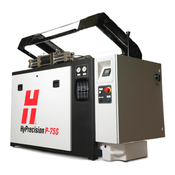
Page 185: Hyprecision P-75S
8 – Pump specifications HyPrecision P-75S Dimensions and weights Length 196 cm (77 in.) Shipping weight 1,600 kg (3,500 lb) Width 97 cm (38 in.) Operating weight 1,500 kg (3,300 lb) Height 155 cm (61 in.) The shipping weight is for the pump, the pallet, and the packaging. Exact weights are measured at shipment. Operating weight is for an unpackaged pump with hydraulic fluid. -
Page 186: Orifices
8 – Pump specifications Orifices Metric (millimeters) Number of HyPrecision HyPrecision HyPrecision HyPrecision HyPrecision HyPrecision orifices P-15 P-30 P-50 P-50S P-60S P-75S 0.18 0.28 0.36 0.36 0.41 0.43 0.13 0.18 0.25 0.25 0.28 0.30 0.10 0.15 0.20 0.20 0.23 0.25 —... -
Page 187: Torque Values
8 – Pump specifications Torque values If a fitting leaks after tightening it to the maximum torque value, disassemble the parts. Repair or replace parts that show deterioration, corrosion, or damage. Do not use an adjustable wrench on high-pressure fittings. WARNING Use only enough torque to make a sufficient seal. -
Page 188: Fittings
8 – Pump specifications SAE J518 flange bolts Lubricate O-rings with hydraulic fluid or O-ring lubricant before installing them. These torque values are for bolts that are coated in antiseize bolt lubricant (white lithium grease). To make a good seal, the sealing face must be parallel to the mating surface and the bolt tension must be even. - Page 189 8 – Pump specifications Special fittings High-pressure water fittings are designed to make a tight seal. If a fitting is installed incorrectly, it can fail. WARNING Do not tighten a fitting too much. The fitting can fail. WARNING Torque Wrench size N∙m lbf ∙...
- Page 190 8 – Pump specifications Hydraulic fittings Hypertherm recommends thread sealant for all NPT fittings. Maximum torque value for a male tapered pipe Size with thread sealant thread with a female straight Standard (inch) (75% of standard maximum) or parallel pipe thread (50% of standard maximum) N∙m...
- Page 191 8 – Pump specifications Steel JIC 37° Lubricate the threads of steel JIC fittings with hydraulic fluid. Minimum Maximum 1/16-inch dash size N∙m lbf ∙ ft N∙m lbf ∙ ft SAE O-ring boss Do not use thread sealant on SAE hydraulic fittings. Lubricate O-rings with hydraulic fluid or O-ring lubricant before assembly.
- Page 192 8 – Pump specifications HyPrecision Predictive waterjet pump Operator Manual 810120...
-
Page 193: Installation
Section 9 Installation In this section Safety Buyer responsibilities Requirements Receive and unpack the equipment Install the pump Install the optional equipment Make the utility connections Do the first start Operator interface: Adjustment screens ... -
Page 194: Safety
9 – Installation Safety Refer to the instruction manual. Read and understand all of the safety guidelines in this manual. A waterjet is a cutting tool. Keep away from high-pressure streams and leaks. Pressurized fluid can cause injuries. A high-pressure injection injury is a surgical emergency. Get medical treatment immediately for all high-pressure waterjet injuries. - Page 195 9 – Installation Do not block or remove warnings, cautions, or instructions. WARNING Do not touch a hot surface. Water leaking from a high-pressure fitting or the bleed-down valve can be hot. CAUTION High-pressure water can cause eye injuries. Wear approved eye protection when operating or doing work near this equipment.
-
Page 196: Buyer Responsibilities
Make all connections to the pump. Fill the hydraulic fluid tank. Hypertherm does not always ship the pump with hydraulic fluid in the tank. Perform user qualification and training. Refer to on page SC-22 for User qualification and training information. -
Page 197: Requirements
Using a chiller with a water-glycol solution can have an effect on the performance of the heat exchanger. Hydraulic fluid For hydraulic fluid specifications, refer to Hydraulic fluid on page 178. Hypertherm does not always ship the pump with hydraulic fluid in the tank. HyPrecision Predictive waterjet pump Operator Manual 810120... -
Page 198: Utilities
Softened water is necessary for most systems. Get advice from a specialist for recommendations for choosing a water treatment system. Reverse osmosis systems are available from Hypertherm. Test the water quality... -
Page 199: Receive And Unpack The Equipment
4. Make sure that the delivery and shipping documents match the equipment that was ordered and what was received. Report shortages or damages to the OEM or to Hypertherm Waterjet within 10 days of receipt of the equipment. -
Page 200: Install The Pump
9 – Installation Install the pump Make sure that all connections, fasteners, locking devices, hoses, and fittings are tight. WARNING These instructions are for a typical installation. In could be necessary to install the components in a different order. Parts, tools, and materials Two 1-1/8-inch open-ended wrenches Level When the unit is in position, use adjustable wrenches to level the unit. - Page 201 9 – Installation 4. Put the cord grip connector on the cord. 5. Put the cord and the threaded end of the cord grip connector through the hole. 6. Put the lock nut on the cord grip connector. 7. Connect the motor wires (L1, L2, and L3) to the motor starter. Connect the ground wire to the grounding lug (PE).
-
Page 202: Install The External Boost Pump (Optional)
9 – Installation Install the external boost pump (optional) An external boost pump is optional for HyPrecision P-15/P-30/P-50 pumps. A boost pump increases the supply water pressure to 7.6 bar (760 kPa / 110 psi). A sustained pressure of lower than 2.8 bar (280 kPa / 40 psi) or meeting the maximum set pressure of 8 bar (800 kPa / 115 psi) causes the pump to turn off. - Page 203 9 – Installation 5. Put the lock nut on the cord grip connector. 6. Connect the motor wires (L1, L2, and L3) to the motor starter. Connect the ground wire to the grounding lug (PE). 7. Tighten the gland nut on the cord. 8.
-
Page 204: Install The External Plumbing Package (Optional)
9 – Installation Install the external plumbing package (optional) The plumbing package is designed to make installing high-pressure tubing from the pump to the cutting table easier. A whip bracket reduces stress on the tubing and the necessity for 90° bends. Parts, tools, and materials 1-15578 Pump-mounted plumbing kit Set of standard wrenches... -
Page 205: Make The Connections To The Utility Panel
9 – Installation Make the connections to the utility panel Compressed air is an energy source that can eject with force. Be careful when connecting to and disconnecting from this energy source. CAUTION Water-cooled system Do not connect the W hose and the C hose together. - Page 206 9 – Installation These fittings are found on the utility panel on the rear of the pump. Refer to Utility panel on page 43 for detailed descriptions. OMPRESSED AIR IN UTTING WATER OUT ASTE WATER OUT UTTING WATER IN OOLING IN OOLING OUT Parts, tools, and materials 13/16-inch open-ended wrench...
-
Page 207: Add Hydraulic Fluid
9 – Installation Refer to Fittings on page 188 for torque values Compressed air operates the bleed-down valve. OMPRESSED AIR IN 1. Connect a compressed air source to this fitting. 1/4-inch NPT female 2. Set the air pressure between 4.8 bar and 5.5 bar (70 psi and 80 psi). This hose carries water from the bleed-down valve and the low-pressure system to a ASTE WATER OUT drain. -
Page 208: Connect The Electrical Power
9 – Installation Connect the electrical power HyPrecision pumps can leak up to 160 mA. To reduce the effects of a high leakage current, connect the pump to a dedicated supply transformer that has separate windings. CAUTION Use electrical parts that are certified by national or local electrical codes. Hydraulic, water, and electrical connections can become loose during shipping and normal operation. -
Page 209: Do The First Start
Do not do the first start with a diamond orifice installed. There is a possibility that the procedure can cause damage to the orifice can during the first start. Hypertherm recommends using a ruby orifice during the first 40 hours of operation. Do a preoperation inspection ... -
Page 210: Make Sure That The Primary Motor Turns In The Correct Direction
9 – Installation Make sure that the primary motor turns in the correct direction It is necessary to have access to a turning shaft for this procedure. Do not put an object or a body part near the shaft while the access cover is off. WARNING COOLED PUMP To prevent damage to the pump, connect the hydraulic hoses between the pump and the external... - Page 211 9 – Installation 4. Turn the pump in cooling mode momentarily. Then touch the symbol. The intent is to make the motor STOP shaft turn so that you can see the direction it moves without starting the pump. OOLING ON 5.
-
Page 212: Make Sure That The Heat Exchanger Fan Motor Turns In The Correct Direction
9 – Installation Make sure that the heat exchanger fan motor turns in the correct direction 1. Operate the pump until the fan turns on. 2. Make sure that the fan motor turns in the direction shown by the rotation arrow. If the fan motor turns in the wrong direction: a. -
Page 213: Turn On The Pump
The supply water components are rated for a maximum of 8.6 bar (860 kPa / 125 psi). CAUTION High pressure can cause damage to the components. If the supply water is from a reverse osmosis system, contact a Hypertherm Technical Service Associate for information and support. HyPrecision P-50S/P-60S/P-75S pump 1. -
Page 214: Measure The Air Pressure In The Water Accumulator Tank
9 – Installation HyPrecision P-15/P-30/P-50 pump (optional) Do not set the boost pump pressure higher than 7.6 bar (760 kPa / 110 psi). The supply water components are rated for a maximum of 8.6 bar (860 kPa / 125 psi). CAUTION High pressure can cause damage to the components. -
Page 215: Flush The Pump And The High-Pressure Tubing
9 – Installation Flush the pump and the high-pressure tubing It is common for small pieces of metal and debris to be present in newly installed high-pressure tubing. Flush the system to prevent damage to orifices, on/off valve parts, and other parts of the high-pressure system. This procedure can cause damage to the on/off valve seals parts and orifices. -
Page 216: Operator Interface: Adjustment Screens
9 – Installation Operator interface: Adjustment screens The adjustment screens on the operator interface let the user change the system configuration. Not all screens are used when installing the pump. Touch the current screen symbol to go back 1 screen. There are 3 ways to interact with the adjustment screens. -
Page 217: Primary Adjustments Screen
9 – Installation 3. Touch a symbol with a border around it. This usually opens another screen. Primary adjustments screen On the operator interface, touch the adjustments symbol to open the primary adjustments screen. Pump Adjustments Intensifier Control Seal Maintenance Indicator Pressures Enter or change the time and date SD Card... - Page 218 Touch the up or down arrows to select the units (bar or psi) that show on the operator interface screens. Software Part # This is the Hypertherm part number for the software installed on the controller. Software Version This is the version of the software on the controller.
- Page 219 9 – Installation Start-procedure Timers All time is in seconds. Ramp Time This is the time that the system takes to increase the high-pressure water from 0 to the high-pressure setpoint. Increase the value to slow the process. The default time is between 3 seconds and 8 seconds, based on the pump model. The value can not be lower than the default.
- Page 220 9 – Installation Pressure Adjustments Maximum This is the maximum pressure that the system can be adjusted to. The default is 4,140 bar (60,000 psi). Increments Increase This is how much that the target pressure increases each time the + symbol on the primary operation screen is touched.
- Page 221 9 – Installation Stop-procedure Timers The pump is idle when the intensifier stops stroking. Stop After Idle When this feature is on, the pump turns off after the idle duration timer expires. Cooling After Idle When this feature is on, the pump goes into cooling mode after the idle duration timer expires. Idle Duration This timer determines how long the pump is idle before it turns off or goes into cooling mode.
- Page 222 9 – Installation Pump Fault Behavior Empty Dirty Water Reminder This turns the reminder feature on or off. Reminder Time This timer determines how long the pump operates before the reminder is displayed. The default is 200 hours. Boost Fault The system can monitor an internal or external boost pump for fault conditions.
- Page 223 9 – Installation Enter or change the time and date Change the date and time that is shown on the operator interface. Time field Date field Touch this symbol to change the time format. Select a 12-hour clock or a 24-hour clock. Touch this date symbol to change the date format.
- Page 224 9 – Installation Total Hours This shows the total hours that the intensifier has been in operation. Strokes This shows the total number of strokes on the intensifier. A stroke is counted each time a proximity switch is on. HyPrecision Predictive waterjet pump Operator Manual 810120...
- Page 225 9 – Installation Pressures This screen shows the supply water pressures and the hydraulic pressures. Water Manifold Actual This shows the pressure coming out of the water manifold. Minimum Touch this field to open a keypad. Enter the minimum pressure permitted before a fault occurs. The default pressure is based on the pump model.
-
Page 226: Remote Operation
To connect the pump directly to an external control device, such as a CNC, refer to the CNC manual and contact a Hypertherm Technical Service Associate for information and support. The electrical interlock is part of the emergency stop circuit. If the top cover is opened while the pump is on, the result is the same as pushing the EMERGENCY STOP button. -
Page 227: Technical Drawings
System schematic for HyPrecision Predictive P-15/P-30/P-50 pumps System schematic for HyPrecision Predictive P-15/P-30/P-50 pumps If you are printing this manual from a PDF, Hypertherm recommends printing these pages on A3-, tabloid-, or ledger-size paper. HyPrecision Predictive waterjet pump Operator Manual 810120... - Page 228 10 – Technical drawings HyPrecision Predictive waterjet pump Operator Manual 810120...
- Page 231 We review your comments and ideas regularly and use them when planning changes. We promise to consider every suggestion. Recommend changes for the next update to this manual. Send this information with your comments to Technical.Service@hypertherm.com: HyPrecision Predictive waterjet pump Operator Manual 810120 Revision 0 ...
Need help?
Do you have a question about the HyPrecision Predictive P-15 and is the answer not in the manual?
Questions and answers