Table of Contents
Advertisement
Quick Links
Advertisement
Table of Contents

Related Manuals for Teledyne GT Series


Summary of Contents for Teledyne GT Series
- Page 1 User Guide User Manual GT SERIES 1 INSTRUMENT, 7 APPLICATIONS 67112 Revision 10...
- Page 2 Sun Microsystems, Inc. All other products or service names are the property of their respective owners. DESCRIPTION This User Guide provides information for use only with the GT Series Portable Gas Monitor (or “the monitor”). LIABILITY Every care has been taken in the preparation of this user guide, but the Company does not accept any responsibility for errors or omissions and their consequences.
- Page 3 GT SERIES 1 INSTRUMENT, 7 APPLICATIONS DISPOSAL ADVICE Dispose of the monitor carefully and with respect for the environment. If returned, the Company will dispose of the monitor without charge. AREAS OF USE Exposure to certain chemicals can result in a loss of sensitivity of the flammable sensor. Where such environments are known or suspected, it is recommended that more frequent response checks are carried out.
-
Page 4: Table Of Contents
GT SERIES 1 INSTRUMENT, 7 APPLICATIONS Table of Contents About This Guide ..............................1 1.1. Guide Conventions ........................1 1.2. Safety............................1 1.2.1. Additional Safety Requirement - CSA Only................2 1.2.2. Certifications And Approvals....................2 1.2.3..........................3 Batteries 1.3. Storage, Handling and Transit ....................3 Introduction ............................4... - Page 5 GT SERIES 1 INSTRUMENT, 7 APPLICATIONS 4.2.5. Button Operation .......................15 4.2.6. Logging ..........................18 4.2.7 Confidence Signal......................18 4.3. Barhole Mode..........................18 4.3.1........................18 Available Ranges 4.3.2. Features ..........................18 4.3.3. Barhole Mode Operation ....................18 4.3.4. Viewing Results........................21 4.3.5. Button Operation .......................21 4.3.6. Faults........................22 Barhole 4.4.
- Page 6 GT SERIES 1 INSTRUMENT, 7 APPLICATIONS 5.5. Warnings & Fault Alarms......................34 5.5.1. Battery Warning ....................... 34 5.5.2........................... 34 Zero Fault 5.5.3. Warm-up)................... 35 Sensor Fault (After 5.5.4......................35 Sample / Flow Fault 5.6. Default Alarm Options......................36 Operator Maintenance.........................
-
Page 7: About This Guide
1 INSTRUMENT, 7 APPLICATIONS 1. About This Guide This guide instructs gas detection personnel on the features and usage of the GT Series of gas detectors (or “the monitor”). It also provides information on configuration, operation, maintenance, specifications and trouble shooting. This user guide assumes the reader has a basic knowledge of gas detection procedures. -
Page 8: Additional Safety Requirement - Csa Only
GT SERIES 1 INSTRUMENT, 7 APPLICATIONS WARNING: TO REDUCE THE RISK OF IGNITION OF A FLAMMABLE OR EXPLOSIVE ATMOSPHERE, BATTERIES MUST BE CHANGED ONLY IN A LOCATION KNOWN TO BE NON-HAZARDOUS. WARNING: TO REDUCE RISK OF EXPLOSION, DO NOT MIX OLD BATTERIES WITH USED BATTERIES OR MIX BATTERIES FROM DIFFERENT MANUFACTURERS. -
Page 9: Batteries
GT SERIES 1 INSTRUMENT, 7 APPLICATIONS 1.2.3 Batteries Caution: Only use approved batteries. 1. UL APPROVED MONITORS: A. Alkaline: Any 'LR14' type B. Rechargeable NiMH: Any 'C' type 2. ATEX/IECEx/CSA APPROVED MONITORS: A. Alkaline: i. Energizer No. E93, Alkaline, (Zn/MnO2), LR14 Size 'C' cell ii. -
Page 10: Introduction
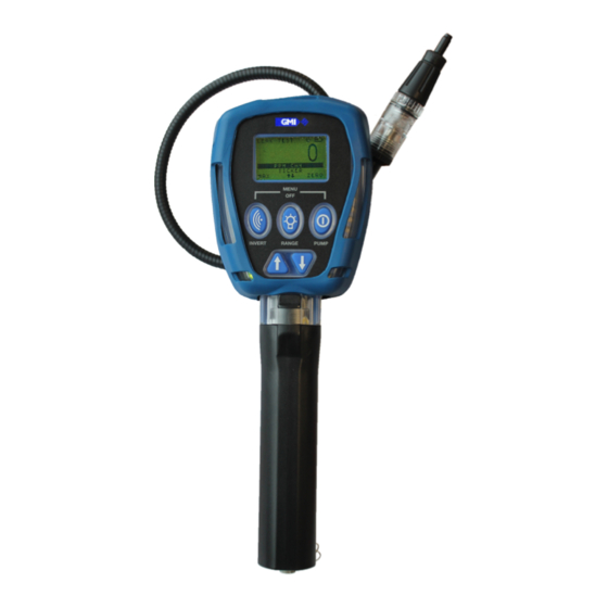
GT SERIES 1 INSTRUMENT, 7 APPLICATIONS 2. Introduction 2.1. Monitor Overview The GMI GT series monitors are multifunction, multi-application gas monitors designed to suit the needs of gas industry service technicians. x‘ Figure 1: GT Series Gas Monitor 2.2. Features •... -
Page 11: Monitor Ranges
GT SERIES 1 INSTRUMENT, 7 APPLICATIONS 2.3. Monitor Ranges The following ranges are available in the GT: • 0-10,000 ppm Methane • 0-100% LEL Methane • 0-100% VOL Methane • 0-25% Oxygen (O • 0-2000 ppm Carbon Monoxide (CO) • 0-100 ppm Hydrogen Sulphide (H •... -
Page 12: Operation
GT SERIES 1 INSTRUMENT, 7 APPLICATIONS 3. Operation 3.1. Operation Procedure Check the following before use: • The monitor is clean and in good condition. • The hydrophobic filter is clean and in good condition. • The clear probe filter bulb is screwed tightly and in good condition. -
Page 13: Monitor Identification
GT SERIES 1 INSTRUMENT, 7 APPLICATIONS • When warm-up is complete, the backlight automatically switches OFF. • The Fault LED illuminates during the warm-up flow fault test. Refer to Figure 2: Switching the Monitor On for more details. 3.3. Monitor Identification... -
Page 14: Time And Date
GT SERIES 1 INSTRUMENT, 7 APPLICATIONS Figure 5: Flow Fault Test To perform a flow fault test: 1. Block probe tip inlet with finger for approximately 5 seconds. 2. If successful, the pump will flow fault and the display will flash SUCCESSFUL, as shown in Figure 6: Successful Test. -
Page 15: Switch The Monitor Off
GT SERIES 1 INSTRUMENT, 7 APPLICATIONS The monitor has five options to alert the user when calibration is due or is overdue: 1. Cal Due disabled - no date is displayed. The monitor does not require a valid calibration to operate. -
Page 16: Service Due
GT SERIES 1 INSTRUMENT, 7 APPLICATIONS Figure 10: Switch Off Note: If the extended period option has expired, the user’s only option will be to switch the monitor OFF. 3.7. Service Due Service Due date allows essential maintenance, e.g. sensor replacement, to be programmed. -
Page 17: Sensor Zeroing
GT SERIES 1 INSTRUMENT, 7 APPLICATIONS Figure 13: Service Due - Switch Off Note: The service due date will only show at 90 days prior to the preset date. 3.8. Sensor Zeroing At the end of warm-up, each sensor is zeroed, as shown in Figure 14: Zero Sensors. - Page 18 GT SERIES 1 INSTRUMENT, 7 APPLICATIONS To switch off the monitor, press and hold both the LH and RH buttons simultaneously for 5 seconds (refer to Figure 15: Switch OFF). Figure 15: Switch OFF The mode selection menu will display for 2 seconds and then a countdown from 3 to OFF, as...
-
Page 19: Modes Of Operation
GT SERIES 1 INSTRUMENT, 7 APPLICATIONS 4. Modes of Operation 4.1. Leak Test Mode Note: The monitor pump must be switched ON to perform correct measurement in Leak Test mode. This mode is used by technicians to investigate odour or leak complaints and pinpoint leaks. -
Page 20: Button Operation
GT SERIES 1 INSTRUMENT, 7 APPLICATIONS Note: Continuous display of both Methane and CO is a configurable option, as shown in Figure 18: Methane + Figure 18: Methane + CO 4.1.4. Button Operation Action Button Note Press Invert Display Displays the Maximum readings since the mode Press and Hold was selected. -
Page 21: Logging
GT SERIES 1 INSTRUMENT, 7 APPLICATIONS Action Button Note Press and Hold Zero the Methane PPM range. Zero Pump must be switched ON. Press and Hold Release 1s after the mode selection menu appears. Mode Selection Use the UP or DOWN buttons to select desired mode. -
Page 22: Confined Space Mode
GT SERIES 1 INSTRUMENT, 7 APPLICATIONS 4.2. Confined Space Mode This mode is used for confined space pre-entry testing and for personal monitoring in areas such as basements. 4.2.1. Available Ranges • 0 - 100% LEL Methane • 0 - 25% Oxygen (O ) if fitted •... -
Page 23: Button Operation
GT SERIES 1 INSTRUMENT, 7 APPLICATIONS Figure 22: Flow Fault Example 4.2.5. Button Operation Action Button Note Press Invert Display 1st press and hold - Maximum gas readings since the mode was selected. Press and Hold 2nd press and hold - Minimum O... -
Page 24: Logging
GT SERIES 1 INSTRUMENT, 7 APPLICATIONS Note: The Max/Min function cannot be used until the alarm is acknowledged. Note: To prevent inadvertently switching monitor OFF or changing mode while alarms are active, the user must press and hold both the LH... - Page 25 GT SERIES 1 INSTRUMENT, 7 APPLICATIONS Figure 23: Barhole Sampling Types 1. To highlight the required option, press the UP or DOWN buttons. 2. To accept the highlighted option, press and hold OK button. Note: Barhole mode of the monitor can be configured to have timed, non-timed or both.
- Page 26 GT SERIES 1 INSTRUMENT, 7 APPLICATIONS Note: The minimum purge time is ten seconds. 4. BARHOLE 1 is displayed as shown in Figure 26: Barhole 1 & Timer. Figure 26: Barhole 1 & Timer 5. Up to six barhole readings can be stored. These are identified as 'BARHOLE 1' to 'BARHOLE 6'.
-
Page 27: Viewing Results
GT SERIES 1 INSTRUMENT, 7 APPLICATIONS Figure 29: Non-Timed Purge 4.3.4. Viewing Results 1. To view previous barhole results press and hold VIEW button. Figure 30: View Barhole Results 2. To return the display to barhole operation, press and hold LIVE button. -
Page 28: Barhole Faults
GT SERIES 1 INSTRUMENT, 7 APPLICATIONS 4.3.6. Barhole Faults If a Flow Fault or Bead Fault is detected, the pump stops automatically. Sampling is aborted if in progress. A Purge cycle will commence. Flow Fault or Bead Fault are recorded as shown in... -
Page 29: Co Sub-Modes
GT SERIES 1 INSTRUMENT, 7 APPLICATIONS 4.4.3. CO Sub-Modes CO mode has four configurable sub-modes as shown in Figure 33: CO Menu. If your monitor only has one enabled, the CO Menu will not be available. Figure 33: CO Menu 1. - Page 30 GT SERIES 1 INSTRUMENT, 7 APPLICATIONS 4.4.3.3. Air-Free CO Air-free CO is the CO reading modified by the O reading. This measurement is only available when an O sensor is fitted. This measurement assists in determining if the emissions from an unventilated appliance (e.g.
-
Page 31: Button Operation
GT SERIES 1 INSTRUMENT, 7 APPLICATIONS To CLEAR all readings from the display, press and hold CLEAR button. 4.4.4. Button Operation Action Button Note Press Invert Display Press and Hold ‘LOG’ briefly appears on the display to confirm Manual Log manual log has been stored. -
Page 32: Purge Mode
GT SERIES 1 INSTRUMENT, 7 APPLICATIONS • Direct CO and Differential CO - the direct CO reading is logged. • Air-Free CO - the calculated reading is logged. A manual log can be taken at any time. A manual zero will also be logged. -
Page 33: Button Operation
GT SERIES 1 INSTRUMENT, 7 APPLICATIONS 4.5.4. Button Operation Action Button Note Press Invert Display Press Range Selection 1st press and hold - backlight ON Press and Hold 2nd press and hold -flashlight ON 3rd press and hold - backlight/flashlight OFF... -
Page 34: Features
GT SERIES 1 INSTRUMENT, 7 APPLICATIONS 4.6.2. Features Sniffer mode features: • Audible / Visual Ticker (Geiger) alarm • Pump ON / OFF (will stop automatically if flow fault is detected) • Ticker threshold adjustment • Display Invert • Backlight •... -
Page 35: Pressure Mode
GT SERIES 1 INSTRUMENT, 7 APPLICATIONS Action Button Note Press and Hold Release 1s after the mode selection menu appears. Mode Selection Use the UP or DOWN buttons to select desired mode. Audible and visual alarms are enabled when Leak Press and Hold mode is selected. -
Page 36: Display
GT SERIES 1 INSTRUMENT, 7 APPLICATIONS 4.7.3. Display Figure 42: Pressure Mode (inch H Note: A configurable option display the pressure reading in mBar as shown in Figure 43: Pressure Mode (mBar). Figure 43: Pressure Mode (mBar) 4.7.4. Performing Pressure Measurements 1. -
Page 37: Button Operation
GT SERIES 1 INSTRUMENT, 7 APPLICATIONS 4.7.5. Button Operation Action Button Note Press Invert Display Press and Hold Screen Backlight Backlight automatically switch OFF after two ON/OFF minutes. Press and Hold Zero Zero the pressure range. Press and Hold Release 1s after the mode selection menu appears. -
Page 38: Alarms
GT SERIES 1 INSTRUMENT, 7 APPLICATIONS 5. Alarms Alarm set-points (instantaneous, STEL and LTEL) are factory set. It is important to verify that the set- points are in accordance with your company's requirements and with local health and safety legislation. -
Page 39: Gas Alarm Examples
GT SERIES 1 INSTRUMENT, 7 APPLICATIONS Note: Alarms are only available in Leak Test and Confined Space modes. By default, Leak Test mode has all the alarm set-points in the table of Default Set-Points of Gas Alarms disabled. 5.3. Gas Alarm Examples... -
Page 40: Acknowledging
GT SERIES 1 INSTRUMENT, 7 APPLICATIONS 5.4.2 Acknowledging User can acknowledge a latching alarm by pressing and holding the AL ACK button. This can only be done after the atmosphere has returned to safe concentrations. 5.4.3 Muting • Alarms can be individually programmable to be mutable. -
Page 41: Sensor Fault (After Warm-Up)
GT SERIES 1 INSTRUMENT, 7 APPLICATIONS 5.5.3 Sensor Fault (After Warm-up) There are two types of sensor faults: 1. 'ZERO FAULT' and a spanner (wrench) symbol alternating with a zero reading, as illustrated in Figure 50: Zero Fault. • Apply relevant test gas for two minutes and then remove it. -
Page 42: Default Alarm Options
GT SERIES 1 INSTRUMENT, 7 APPLICATIONS 5.6. Default Alarm Options Audible Visual LED Alarm Type Latching? Mutable? Indication Indication LEL Warning Alarm disabled by default LEL (HI) High Pitch 4x LED Flashing LEL (HIHI) High Pitch 8x LED Ramping (LO) -
Page 43: Operator Maintenance
Location). Refer to Section 1.2.3 Batteries for the allowed battery types. Figure 52: GT Series Battery Location 6.1.1 Replacing Batteries WARNING: BATTERIES MUST BE CHANGED ONLY IN A LOCATION KNOWN TO BE NON-HAZARDOUS. WARNING: DO NOT MIX NEW BATTERIES WITH USED BATTERIES OR MIX BATTERIES FROM DIFFERENT MANUFACTURERS. - Page 44 GT SERIES 1 INSTRUMENT, 7 APPLICATIONS 1. Unscrew the captive thumb screw from the battery cover assembly. 2. Press the securing catch to release the battery cover assembly. 3. Remove the cover in direction shown in Figure 53: Battery Cover Removal.
-
Page 45: Charging Batteries
GT SERIES 1 INSTRUMENT, 7 APPLICATIONS Figure 55: O-Ring Replacement 7. Reattach all parts (reverse of removal procedure). 6.1.2 Charging Batteries WARNING: NEVER RECHARGE NON RECHARGEABLE CELLS. Caution: Switch the monitor off when charging batteries. There are three options for charging batteries fitted inside the monitor: •... - Page 46 GT SERIES 1 INSTRUMENT, 7 APPLICATIONS The green ‘Power’ LED is on during charging. When charging is complete, the screen shown in Figure 57: Charging Complete is displayed. Figure 57: Charging Complete If 'CHARGING TERMINATED' is displayed, as shown in...
- Page 47 Refer to Charging Station Instruction Sheet (P/N 67252) for more details. Figure 60: GT Series Charging Station To insert monitor in charging station: 1. Check that monitor charging contacts (shown in Figure 61: Monitor Charging Contacts) and...
- Page 48 2. Ensure the monitor is switched OFF. 3. Locate the hole on the base of the monitor handle and insert onto the charging station, refer to Figure 60: GT Series Charging Station. 4. Secure monitor into the storage clip and engage securing strap, refer to...
- Page 49 GT SERIES 1 INSTRUMENT, 7 APPLICATIONS 5. Secure the probe in the charging station, as shown in Figure 60: GT Series Charging Station. 6. Connect power supply, (Universal Power Supply (part no. 12444) or 12V Vehicle Power Supply (part no. 12988)) to Charging Station as shown in...
-
Page 50: Cleaning
GT SERIES 1 INSTRUMENT, 7 APPLICATIONS 6.2. Cleaning Caution: Do not use agents containing silicon or solvent to clean the monitor as these may damage the flammable gas sensor. Caution: Do not use abrasive materials or strong volatile chemical solutions as these could damage the impact resistant casing. -
Page 51: Hydrophobic Filter
GT SERIES 1 INSTRUMENT, 7 APPLICATIONS Figure 65: Dust Filter Holder / Filter Removal 6.3.2 Hydrophobic Filter Note: When replacing the hydrophobic filter, you must also replace the dust filter. Caution: The monitor must be OFF when replacing the hydrophobic filter. -
Page 52: Chemical Filter (Optional Accessory)
Caution: The contents of this filter must only be replenished with Teledyne GMI approved chemicals. Note: When replacing the chemical filter, you must also replace the dust filter. 1. Remove and discard the dust filter, as detailed in Section 6.3.1 Dust... - Page 53 GT SERIES 1 INSTRUMENT, 7 APPLICATIONS Figure 67: Filter Removal 4. If the content of the chemical filter is to be replaced, hold the filter assembly in the upright position, as shown in Figure 68: Filter Housing Adaptor Removal. Unscrew the filter housing adaptor.
-
Page 54: Cotton Filter (Optional Accessory)
GT SERIES 1 INSTRUMENT, 7 APPLICATIONS Figure 69: Housing Filter Removal The housing adaptor filter must also be replaced if damaged or contaminated. Using the flat end of a pencil or similar, push the filter from the open end of the adaptor, as... - Page 55 GT SERIES 1 INSTRUMENT, 7 APPLICATIONS Figure 71: Cotton Filter Removal 1. Using a pencil, push the cotton filter from the threaded end of the housing, as shown in Figure 72: Cotton Filter Removal, then remove it. Figure 72: Cotton Filter Removal 2.
-
Page 56: Bump Test
GT SERIES 1 INSTRUMENT, 7 APPLICATIONS 7. Bump Test A bump test verifies sensor response and alarm operation by exposing the monitor to a known concentration of gas. There are two bump test options: • Automatic - using GT Calibration Station •... - Page 57 GT SERIES 1 INSTRUMENT, 7 APPLICATIONS Note: Bump Test mode will only display gas ranges configured in the monitor. Multiple gas cylinders may be required to fully bump test the monitor. Each gas cylinder used is referenced using a CalGas number.
-
Page 58: Viewing Bump Test Results
GT SERIES 1 INSTRUMENT, 7 APPLICATIONS Figure 77: Applied Gas Peak Values • Left column - gas ranges available in the monitor • Middle column - concentration of gas being applied • Right column -peak gas reading 4. Apply the gas using a demand flow regulator. -
Page 59: Bump Test Logging
GT SERIES 1 INSTRUMENT, 7 APPLICATIONS To return to CalGas Display, press and hold the OK button. 7.2.3 Bump Test Logging All manual bump tests results will be automatically stored in the monitor's memory when the mode is exited using the EXIT button. -
Page 60: Calibration
3. The GMI GT-Series Automatic Calibration System. This provides controlled delivery of individual / mixed gases, allowing calibration with records stored on a PC. Note: For further information on calibration options, please contact Teledyne GMI or an authorized distributor. 8.1. Calibration Validity Calibration validity remains the responsibility of the user. -
Page 61: Accessories
GT SERIES 1 INSTRUMENT, 7 APPLICATIONS 9. Accessories Accessories and spare parts available for the GT series monitors are as follows: 9.1. Consumables Part No. Description 67163 Dust Filter - Box of 30 67196 Cotton Filter 10077 Cotton Filter - Box of 10 (use with 67196) -
Page 62: Spare Parts
GTCAL System Package (including CD and interface) 67164 GT Data Downloading Package (including CD and interface) 67216 GT Set-up Software Package (including CD and interface) For a comprehensive list of probes, accessories and calibration gases, contact your local distributor or alternatively, Teledyne GMI. 67112 Revision 10... -
Page 63: Monitor Specifications
GT SERIES 1 INSTRUMENT, 7 APPLICATIONS Appendix A. Monitor Specifications Range Span Resolution Sensor Type Methane (CH ) ppm 0 - 10,000ppm Semiconductor 1ppm 0 to 100% Methane (CH ) LEL Catalytic Bead 0 to 9.9% 0.1% Methane (CH ) Vol... -
Page 64: Technical Support
GT SERIES 1 INSTRUMENT, 7 APPLICATIONS Appendix B. Technical Support This product is designed to provide you with reliable, trouble-free service. Contact your regional technical support if you have technical questions, need support, or if you need to return a product. - Page 65 GT SERIES 1 INSTRUMENT, 7 APPLICATIONS This page is intentionally left blank. 67112 Revision 10...
- Page 66 Renfrew, PA4, 9RG Pudang, Shanghai 201206 TX 77381, USA Scotland, UK People’s Republic of China Tel.: +1-713-559-9200 Tel.: +44 (0) 141 812 321 1 Tel.: +86-21-3127-6373 www.teledynegasandflamedetection.com 67112 Revision 10 Copyright © 2020 Teledyne Gas and Flame Detection. All rights reserved.
Need help?
Do you have a question about the GT Series and is the answer not in the manual?
Questions and answers