Table of Contents
Advertisement
Quick Links
Advertisement
Table of Contents

Related Manuals for Teledyne OLCT 60


Summary of Contents for Teledyne OLCT 60
- Page 1 SER MANUAL OLCT 60 FIXED POINTGAS MONITOR NPO60GB Revision: F.2...
- Page 2 User Manuals in other languages are available on Website https://teledynegasandflamedetection.com Copyright March 2021 by TELEDYNE OLDHAM SIMTRONICS S.A.S. All rights reserved. No reproduction of all or part of this document, in any form, is permitted without the written consent of TELEDYNE OLDHAM SIMTRONICS S.A.S.
- Page 3 No business, person or legal entity may assume responsibility on behalf of TELEDYNE OLDHAM SIMTRONICS, even though they may be involved in the sale of TELEDYNE OLDHAM SIMTRONICS products.
- Page 4 • halogenated compounds (R134a, HFO, etc.) • organo-phosphorus compounds (e.g. herbicides, insecticides, and phosphate esters in fireproof hydraulic fluids TELEDYNE OLDHAM SIMTRONICS recommends regular testing of fixed gas detection installations (read Preventive maintenance). Warranty Under normal conditions of use and on return to the factory, parts and workmanship are guaranteed for 2 years, excluding consumables such as sensors, filters, etc.
-
Page 5: Table Of Contents
OLCT 60 FIXED POINTGAS MONITOR USER MANUAL Contents Overview ................... 1 Operating principle ..................2 Composition of the Detector ................ 2 External view ....................... 3 Internal view ......................5 Labels and pictograms ................... 5 Visual indication ....................6 Installation ..................9 Regulations and conditions of use ............. - Page 6 OLCT 60 FIXED POINTGAS MONITOR USER MANUAL Initialization of the sensor block ..............24 Zeroing and sensitivity adjustment (calibration) ........26 Applicable coefficients for explosive gas calibration ......31 Checking the line current ................34 Menu “TEST” ......................35 Accessories ..................39 Spare parts ..................
-
Page 7: Overview
Table 1: Comparison of OLCT 60 detectors Each version features two options: • OLCT 60 version with on-board sensor. The sensor can either be flameproof or intrinsically safe certified depending on the version of the detector. • OLCT 60D version with remote sensor. The sensor can either be flameproof or intrinsically safe certified depending on the version of the detector. -
Page 8: Operating Principle
(gas controller or PLC). Sensor type depends on the gas to be detected and the version of OLCT 60 as shown in Table 1: Comparison of OLCT 60 detectors on page 1. -
Page 9: External View
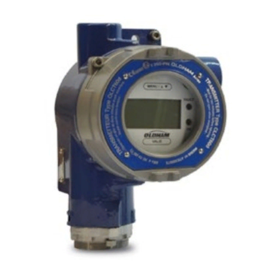
OLCT 60 FIXED POINTGAS MONITOR USER MANUAL Figure 1: Main components of OLCT 60 detectors 1.3 External view 1.3.1 Overview Description Digital display. See Figure 3 for more details. Ground terminal Cover fixation screw Cable gland (until August 2014) On-board sensor. - Page 10 OLCT 60 FIXED POINTGAS MONITOR USER MANUAL 1.3.2 Difference between FLP and IS sensors Although they have different ATEX marking, intrinsically safe and flameproof sensors are distinguished by the color of the sensor block as following: • Flameproof sensor: unpainted Stainless steel enclosure equipped with a flame arrestor, •...
-
Page 11: Internal View
P/N label This label is located on the side of the enclosure and contains the following information: Description Part Number of the OLCT 60 without sensor Disposal icon Serial Number : The first two digits (in this case 10) Figure 6: Side label... -
Page 12: Visual Indication
Indicator OLCT 60 is powered OLCT 60 is not powered FAULT Detector in fault or in maintenance Normal Operation mode See Fault mode screen Figure 8: OLCT 60 in normal operating mode NPO60GB Revision F.2... - Page 13 Figure 9: OLCT 60 in fault mode Maintenance Menus They allow maintenance operations to be carried out (calibration, resetting of cell parameters, verification of the correct functioning of the display and the output current generator).
- Page 14 OLCT 60 FIXED POINTGAS MONITOR USER MANUAL Gas calibration menu The OLCT 60 detector has three menus (CAL, INIT and TEST). Normal operating mode (page 18) (page 26) (page 350) (page 35) Figure 11: Gas calibration menu • CAL: zero and span calibration. See page 26.
-
Page 15: Installation
OLCT 60 FIXED POINTGAS MONITOR USER MANUAL Installation Please read the guidelines on the installation, use and maintenance of detectors for detection of flammable gases and oxygen (standard EN/IEC 60079-29-2) and toxic gases (standard EN 45544-4). 2.1 Regulations and conditions of use •... -
Page 16: Detector Positioning
2.4.1 All versions excluding GD10P The OLCT 60 will be installed with the sensor pointing downwards. Any tilt of more than 45° from the vertical will lead to an inaccurate measurement. Fixing the enclosure will be performed by using 2 x M6 screws and the appropriate plugs for the supporting material. -
Page 17: Electrical Specifications
OLCT 60 FIXED POINTGAS MONITOR USER MANUAL Figure 14: GD10P detector MUST be laid horizontally, indicator pointing upwards 3 meters minimum 30 meters maximum Figure 15: OLCT IR detector must be laid horizontally, indicator pointing upwards 2.5 Electrical Specifications Type of sensor... -
Page 18: Connecting Cable
OLCT 60 FIXED POINTGAS MONITOR USER MANUAL 2.6 Connecting cable The detector shall be connected to the controller with a 3-wire shielded cable. Core size depends on the specific requirements of the installation, the distance and type of detector (see table below). - Page 19 OLCT 60 FIXED POINTGAS MONITOR USER MANUAL 2.7.2 Opening of the detector Loosen the 4mm hex screw (rep.1) locking the cover before removing the detector cover. Figure 16: Locking screw of the cover 2.7.3 Cable preparation The cable will be supplied from the controller at the measurement point. The passage, support, and protection of the cable shall be done according to best practice.
- Page 20 USER MANUAL 2.7.5 Cable connection (OLCT 60) Remove power before wiring the OLCT 60 to the controller. The site must be equipotential. Connect the cable to the detector first and then connect the controller. Once the wiring is completed, connect the shield of the cable to the ground terminal of the controller.
- Page 21 Connect the enclosure ground points to earth according to the regulations with a 4mm² (11 AWG) wire. The OLCT 60 features an internal ground point as well. The internal grounding shall be preferred as the primary equipment ground. Figure 21: OLCT 60 grounding 2.7.8...
-
Page 22: Scope Of Use
% of the transmitter. Similarly, the unit should provide measuring range sufficient voltage to compensate for any voltage Default drop in the cable. Figure 22: OLCT 60 transfer curve NPO60GB Revision F.2... -
Page 23: Commissioning And Operating Modes
OLCT 60 FIXED POINTGAS MONITOR USER MANUAL Commissioning and operating modes The tasks described in this chapter should only be performed by authorized and trained personnel as they are likely to jeopardize the reliability of detection. This chapter describes: • how to check the zero •... -
Page 24: Commissioning
3.3.2 Powering up detector 1. Inhibit any alarms to avoid false alarms during operation 2. Apply power to the OLCT 60 3.4 Stabilization time Before initial calibration allow the detector to stabilize after applying power. Any adjustment before the time indicated will result in an incorrect measurement, which may in turn compromise the safety. -
Page 25: Checking Zero
OLCT 60 FIXED POINTGAS MONITOR USER MANUAL 3.5.2 Fault mode In fault condition, the display indicates «dEF» followed by the fault code. In the event of an internal electronic error, the display indicates «E» followed by the error code. FAULT In both cases, the indicator is lit. -
Page 26: Checking Gas Sensitivity
OLCT 60 FIXED POINTGAS MONITOR USER MANUAL 4. Apply the gas (flow regulator set to 0.5-1.0 liter per minute (LPM). For GD10P versions refer to GD10P manual. 5. Once the measure is stabilized (approx. 2 minutes), read the value on the display (rep. A). -
Page 27: Preventive Maintenance
4.1 Maintenance schedule Gas detectors are safety devices. TELEDYNE OLDHAM SIMTRONICS recommends the regular testing of fixed gas detection installations. This type of test consists of injecting the calibration gas into the detector at a sufficient concentration to activate the pre-set alarms. It is to be understood that this test is in no way a replacement for a detector calibration. - Page 28 • Zero inspection with zero grade air; see page 19. In case of variance, comply with the actions described in this paragraph. • Gas sensitivity check; see page 19. In case of variance, comply with the actions described in this paragraph. 4.2.2 OLCT 60/ GD10P Refer to the specific GD10P manual. NPO60GB Revision F.2...
-
Page 29: Maintenance
OLCT 60 FIXED POINTGAS MONITOR USER MANUAL Maintenance Maintenance primarily comprises changing any sensors that no longer meet their initial metrological characteristics. Since they are liable to affect detection reliability, the tasks described in this chapter are reserved for authorized trained personnel only. Inspection and maintenance shall be carried out in accordance with EN/IEC 60079-17 standards in force or with other national standards. -
Page 30: Initialization Of The Sensor Block
Reassemble in reverse order and tighten the locking screw. Power the OLCT 60. Install the OLCT 60 as explained in detail in the Initialization of the sensor block paragraph on page Erreur ! Signet non défini.. 5.3 Initialization of the sensor block Init 5.3.1... - Page 31 OLCT 60 FIXED POINTGAS MONITOR USER MANUAL Step Action Illustration The initialization menu (Init) is displayed. 5.3.2 Initialization of the sensor block This procedure resets the electrical parameters of the sensor. Step Action Illustration Init screen is displayed, place the magnet over Confirmation The display indicates «CnF»...
-
Page 32: Zeroing And Sensitivity Adjustment (Calibration)
In the event of a voluntary or an automatic abandon of the procedure, the previous values will be maintained. OLCT 60 leaves the maintenance mode and returns to normal operation after 10 minutes of inactivity on the The detector cover shall remain completely closed since the adjustments are carried out through the window. - Page 33 OLCT 60 FIXED POINTGAS MONITOR USER MANUAL Step Action Illustration Until the icon is displayed..present the magnet 3 consecutive times on the in the 3 seconds. The calibration menu (CAL) is displayed. 5.4.2 Zeroing Step Action Illustration The calibration menu (CAL) is displayed.
- Page 34 OLCT 60 FIXED POINTGAS MONITOR USER MANUAL 5.4.3 Adjustment of gas sensitivity Accessing the sensitivity adjustment menu Step Action Illustration Span Gas «GE» ( ) is displayed to indicate that the system has switched over to the sensitivity adjustment phase.
- Page 35 OLCT 60 FIXED POINTGAS MONITOR USER MANUAL Step Action Illustration to GD10P manual). Position the magnet over The displayed value keeps changing until it stabilizes. Wait approximately 2 minutes for the stabilization of the measure. As soon as the instrument stabilizes at a value, place the magnet over to exit the sensitivity adjustment function.
- Page 36 5.4.5 End of the zero-setting and calibration procedure Step Action Illustration The OLCT 60 starts a countdown before returning in normal operation mode. Please note: The countdown time is sensor dependent. Close the cock of the calibration gas cylinder and remove the calibration cup.
-
Page 37: Applicable Coefficients For Explosive Gas Calibration
OLCT 60 FIXED POINTGAS MONITOR USER MANUAL 5.5 Applicable coefficients for explosive gas calibration 5.5.1 Catalytic sensor type VQ1 The applicable coefficients are shown in the following table. Chemical Flash Vapor Coefficient Coefficient - Coefficient Coefficient Formula point density Calibration (°C) - Page 38 OLCT 60 FIXED POINTGAS MONITOR USER MANUAL Chemical Flash Vapor Coefficient Coefficient - Coefficient Coefficient Formula point density Calibration (°C) Calibration Calibration Calibration C4H10 C5H12 (Hydrogen) (methane) (Butane) (Pentane) Isobutene C4H8 1,60 10,00 <-10 2,20 1,80 1,20 1,05 Isopropanol C3H8O...
- Page 39 OLCT 60 FIXED POINTGAS MONITOR USER MANUAL 5.5.2 4F poison resistant catalytic bead sensor The applicable coefficients are: C5H1 Chemical Vapor LEL % LSE % Coef Formula density Coef Coef Acetone C3H6O 2,15 13,0 2,24 1,03 Acetylene C2H2 1,91 Ammoniac...
-
Page 40: Checking The Line Current
OLCT 60 FIXED POINTGAS MONITOR USER MANUAL 5.6 Checking the line current + 24 VDC Signal Figure 28: Checking the current generator of the detector Proceed as follows: 1. Check the detector for proper power supply (+24V between terminal 2 and 3). -
Page 41: Menu "Test
OLCT 60 FIXED POINTGAS MONITOR USER MANUAL 5.7 Menu “TEST” The Test menu allows the user to check the operation of the LEDs, the LCD screen and the 4-20mA output. tESt Accessing the Autotest ( ) menu Step Action Illustration After the startup phase, the screen will show the gas measurement (it may be wrong at this point). - Page 42 OLCT 60 FIXED POINTGAS MONITOR USER MANUAL Step Action Illustration The "FAULT" and OK LEDs flash one after the other. To stop the test or go to next test, Place the magnet over LCD test display. To run the test, Place the magnet over The display will flashing.
- Page 43 OLCT 60 FIXED POINTGAS MONITOR USER MANUAL Step Action Illustration To stop the test or go to next test, Place the magnet over Back to the 4-20mA test menu. To stop the test or, Place the magnet over Place the magnet over...
- Page 44 OLCT 60 FIXED POINTGAS MONITOR USER MANUAL NPO60GB Revision F.2...
-
Page 45: Accessories
OLCT 60 FIXED POINTGAS MONITOR USER MANUAL Accessories The following accessories do not apply for OLCT 60 versions with GD10P. For the latter please refer to the GD10P manual. Accessories Utilization Illustration Illustration Tool Kit Opening of the OLCT 60 and sensor... - Page 46 OLCT 60 FIXED POINTGAS MONITOR USER MANUAL Accessories Utilization Illustration Illustration Remote Allows gas detection and the use of a 6327911 calibration tubing for calibration gas injection. For Plastic material. combustible gases only. Flow rate 1 LPM Risk of minimum.
-
Page 47: Spare Parts
FIXED POINTGAS MONITOR USER MANUAL Spare parts Spare parts list for different detectors Spare parts must be original TELEDYNE OLDHAM SIMTRONICS parts. Use of non- original spare parts may impair safety of the instrument. 7.1 Explosionproof sensor block Illustration Description... -
Page 48: Intrinsically Safe Sensors
H2-compensated sensor block OLCT 60 CO 0-1000 ppm 6 313 695 Sensor block OLCT 60 H2S 0-30 ppm 6 313 965 Sensor block OLCT 60 H2S 0-30 ppm, no HC-interference 6 313 696 Sensor block OLCT 60 H2S 0-100 ppm 6 313 697... - Page 49 Sensor block OLCT 60 SI SiH4 0-50 ppm 6 313 926 Sensor block OLCT 60 SI CVM 0-200 ppm (before December 2018,1 6 313 747 Sensor block OLCT 60 SI CVM 0-200 ppm (since December 2018, 1 NPO60GB Revision F.2...
- Page 50 OLCT 60 FIXED POINTGAS MONITOR USER MANUAL NPO60GB Revision F.2...
-
Page 51: Declaration Of Eu Conformity
OLCT 60 FIXED POINTGAS MONITOR USER MANUAL Declaration of EU Conformity NPO60GB Revision F.2... - Page 52 OLCT 60 FIXED POINTGAS MONITOR USER MANUAL NPO60GB Revision F.2...
-
Page 53: Technical Specifications
OLCT 60 FIXED POINTGAS MONITOR USER MANUAL Technical Specifications 9.1 Dimensional characteristics Figure 29: Dimensional characteristics of OLCT 60 detectors with on-board and remote sensor NPO60GB Revision F.2... - Page 54 OLCT 60 FIXED POINTGAS MONITOR USER MANUAL Figure 30: Dimensional characteristics of OLCT 60 equiped with GD10P mounting on plate NPO60GB Revision F.2...
-
Page 55: Complete Detector
OLCT 60 FIXED POINTGAS MONITOR USER MANUAL 9.2 Complete detector • 16 to 30 Vdc Power supply to the detector 18 to 30 Vdc (versions with GD10P) terminals • Catalytic: 100 mA Average consumption @24Vdc • Electrochemical: 55 mA based on the sensor block type •... -
Page 56: Measuring Sensors
OLCT 60 FIXED POINTGAS MONITOR USER MANUAL 9.3 Measuring sensors Average Temperature Storage Measuring Resp. Time Accuracy (ppm) LifeExpe range range % HR T50/T90 time and ctancy sensor sensor @20°C (ppm) (°C) conditions (months) +/- 3% (from 0 to 50%... - Page 57 OLCT 60 FIXED POINTGAS MONITOR USER MANUAL Average Temperature Storage Measuring Resp. Time Accuracy (ppm) LifeExpe range range % HR T50/T90 time and ctancy sensor sensor @20°C (ppm) (°C) conditions (months) +/- 0.03 (from 0 to 0,2 ppm) Ozone 1.00 0 to +40 10 –...
- Page 58 OLCT 60 FIXED POINTGAS MONITOR USER MANUAL Average Temperature Storage Measuring Resp. Time Accuracy (ppm) LifeExpe range range % HR T50/T90 time and ctancy sensor sensor @20°C (ppm) (°C) conditions (months) +/- 15% (from 20 to 70% Freon R407 c 1000 -20 to +55 20 –...
-
Page 59: Special Instructions For Use In Explosive Environments And Functional Safety
10.1 General comments The OLCT 60 sensors conform to the requirements of European Directive ATEX 2014/34/UE relating to explosive Dust and Gas atmospheres. On account of their metrological performance (currently under re-evaluation of the certification with the notified body INERIS following the... -
Page 60: Threaded Joints
The threaded joints on the OLCT 60 may be lubricated to ensure protection against explosions. Only non-hardening lubricants or non-corrosive agents without volatile solvents may be used. -
Page 61: Operation Under Low Oxygen Levels
10.11 Functional Safety The safety function of the OLCT 60 detector is the detection of flammable gases using catalytic technology or the detection of oxygen using an electrochemical cell and a 4-20 mA current output proportional to the gas concentration expressed as a percentage of LEL (from 0 to 100% LEL) or expressed as a percentage of volume of oxygen (from 0 to 30% vol. -
Page 62: Marking
OLCT 60 FIXED POINTGAS MONITOR USER MANUAL 10.13 Marking OLCT60d type(with on-board sensor, ‘d’ type) TELEDYNE OLDHAM SIMTRONICS SAS ZI EST 62027, ARRAS France OLCT60 d CE0080 INERIS 01ATEX0027X II 2 G D Ex db IIC T6 Gb Ex tb IIIC T85°C Db T.Amb : -20°C à... - Page 63 Ex db IIC T6 Gb Ex tb IIIC T85°C Db T. Amb : -20°C à 70°C Do not open when energized. WARNING: OLCT60 id detrector(with local sensor, ‘i’ type) TELEDYNE OLDHAM SIMTRONICS SAS ZI EST 62027, ARRAS France OLCT60 id CE0080 INERIS 01ATEX0027X...
- Page 64 OLCT 60 FIXED POINTGAS MONITOR USER MANUAL Ex db [ia Ga] IIC T4 Gb Ex tb [ia Da] IIIC T135°C Db T. Amb : -20°C à 60°C WARNING: Do not open when energized. After de-energizing, delay 2 minutes before opening. Read user manual (cable glands)
-
Page 65: Fault And Error Codes
OLCT 60 FIXED POINTGAS MONITOR USER MANUAL Fault and error codes E xx 11.1 Errors ( Errors are exclusively generated when a communication trouble occurs between the sensor and the internal board. Errors are identified in the following format (whereas corresponds to the error code). - Page 66 OLCT 60 FIXED POINTGAS MONITOR USER MANUAL NPO60GB Revision F.2...
- Page 67 OLCT 60 FIXED POINTGAS MONITOR USER MANUAL NPO60GB Revision F.2...
- Page 68 Z.I. Est – CS 20417 Ruiping Road, Xuhui District TX 77429, 62027 ARRAS Cedex, SHANGHAI FRANCE CHINA Tel.: +1-713-559-9200 Tel.: +33 (0)3 21 60 80 80 Tel.: +86-134-8229-5057 www.teledynegasandflamedetection.com © 2021 Teledyne Oldham Simtronics. All right reserved. NPO60GB Revision F.2 / March 2021...
Need help?
Do you have a question about the OLCT 60 and is the answer not in the manual?
Questions and answers