Table of Contents
Advertisement
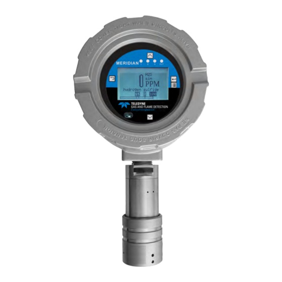
MERIDIAN
UNIVERSAL GAS DETECTOR
WARNING: ALL INDIVIDUALS WHO, HAVE OR WILL HAVE, RESPONSIBILITY FOR USING,
MAINTAINING, OR SERVICING THIS PRODUCT, MUST READ THIS ENTIRE MANUAL CARE-
FULLY. FAILURE TO USE THIS EQUIPMENT PROPERLY COULD RESULT IN SERIOUS INJURY OR
DEATH.
Information contained herein is classified as EAR99 under the U.S. Export Administration Regulations. Export, reexport or diversion contrary
USE AND DISCLOSURE OF DATA
to U. S. law is prohibited.
User Guide
User Guide
087-0049, Rev. G / June 2020
Advertisement
Table of Contents

Related Manuals for Teledyne Meridian


Summary of Contents for Teledyne Meridian
- Page 1 User Guide User Guide MERIDIAN UNIVERSAL GAS DETECTOR WARNING: ALL INDIVIDUALS WHO, HAVE OR WILL HAVE, RESPONSIBILITY FOR USING, MAINTAINING, OR SERVICING THIS PRODUCT, MUST READ THIS ENTIRE MANUAL CARE- FULLY. FAILURE TO USE THIS EQUIPMENT PROPERLY COULD RESULT IN SERIOUS INJURY OR DEATH.
- Page 2 MERIDIAN UNIVERSAL GAS DETECTOR REVISION HISTORY Revision History Reason Rev. No. Rev. Date — Initial Release Updated CSA approvals, added information for Tech Support in Hous- ton; added or clarified several other notes and specifications. Numerous updates to configuration, maintenance, specification and sen- sor chapters to support 8 new combustible IR part numbers and cat-bead k-factors.
- Page 3 Provides information on the various Optional Communica- 087-0050 Guide tion Expansion Cards (CEC) PCBs. Cross Sensitivity Table Provides cross sensitivity information for Meridian electro- 062-0064 Reference chemical sensors to other common gases. Sensor Data Sheet Provides detailed sensor specifications for each of the...
- Page 4 MERIDIAN UNIVERSAL GAS DETECTOR RELATED PRODUCT DOCUMENTATION This page is intentionally left blank. USE AND DISCLOSURE OF DATA Information contained herein is classified as EAR99 under the U.S. Export Administration Regulations. Export, reexport or diversion contrary to U. S. law is...
- Page 5 LEGAL STATEMENT Teledyne Gas and Flame Technologies, the Teledyne Gas and Flame Technologies logo, the Teledyne rhomboid, and Meridian are registered and/or unregistered marks of Teledyne Gas and Flame Technologies, also referred to as “the Company.” All rights reserved. No part of this documentation may be reproduced in any form or by any means or used to make any derivative work (such as translation, transformation, or adaptation) without written permission from the Company.
- Page 6 MERIDIAN UNIVERSAL GAS DETECTOR LEGAL STATEMENT This page is intentionally left blank. USE AND DISCLOSURE OF DATA Information contained herein is classified as EAR99 under the U.S. Export Administration Regulations. Export, reexport or diversion contrary to U. S. law is...
-
Page 7: Table Of Contents
Mounting & Wiring the Junction Box Assembly (AL or SS) 4-21 4.1.15. Remotely Mounted Sensor Calibration Fitting 4-24 4.1.16. Meridian Junction Box Assembly Spacer Kit 4-25 4.1.17. Mounting the Detector Body Using a Duct Mount Fitting 4-26 USE AND DISCLOSURE OF DATA Information contained herein is classified as EAR99 under the U.S. - Page 8 Connecting a Device to a Power Supply: 2-wire 4-31 4.1.20. Connecting a Device to a Power Supply & Receiver: 4-wire 4-33 4.1.21. Connecting a Device to Other Teledyne DETCON Receivers 4-37 4.1.22. Connecting Optional Relays & Remote Alarm Reset 4-37 4.1.23.
- Page 9 Trimming the 4-20mA Loop 7-17 7.3.8. Replacing the LCD PCB/CPU PCB 7-18 7.3.9. Replacing the Terminal/Relay/MODBUS RS-485 PCB 7-19 7.3.10. Replacing the Meridian NPT Ex Seal 7-20 7.3.1 1. Replacing the Meridian Detector Body Assembly 7-22 7.3.12. Re-mapping the Sensors 7-24 7.3.13.
- Page 10 MERIDIAN UNIVERSAL GAS DETECTOR TABLE OF CONTENTS Table of Contents (Continued) Sect. # Section Title Page # B.3.1. Using Target Gas Other than Methane B.3.2. Using Methane as a Surrogate Gas B.3.3. Using Propane as a Surrogate Gas B.4. Combustible IR Sensor Surrogate Test Gas B-10 B.5.
- Page 11 Retrofit Mounting Plate Dimensions - HDPE 4-17 NPT Ex Seal Installation 4-19 Meridian Junction Box Assembly Wiring and Mounting – Aluminum 4-21 Meridian Junction Box Assembly Wiring and Mounting – Stainless Steel 4-22 4-10 Remotely Mounted Sensor with Calibration Fitting 4-23 4-1 1...
- Page 12 MERIDIAN UNIVERSAL GAS DETECTOR LIST OF FIGURES List of Figures (Continued) Fig. # Figure Title Page # Setup Menu Structure Calibration Menu Structure 5-17 Datalog Menu Structure 5-18 Display Menu Structure 5-21 User Access Menu Structure 5-22 Text and Numeral Display...
- Page 13 Hard Wired Configurations – Sensor Types Supported for 2-Wire Typical Cable Data for Input Power Length Considerations 4-10 Parts Required for Application Solution Example 4-12 Installation Checklist 4-14 Meridian Junction Box Assembly Spacer Configurations 4-24 4-10 Sourcing and Sinking Non-Isolated (SW1) Settings 4-30 4-1 1 WiredHART (J3) Settings...
- Page 14 MERIDIAN UNIVERSAL GAS DETECTOR LIST OF TABLES List of Tables (Continued) Table# Table Title Page # Change user Access Setup Menu Parameters 5-15 Backup/Restore Setup Menu Parameters 5-16 Calibration Menu Parameters 5-17 Datalog Menu Parameters 5-18 Display Setup Menu Parameters...
- Page 15 MERIDIAN UNIVERSAL GAS DETECTOR LIST OF TABLES List of Tables (Continued) Table# Table Title Page # Recommended Maintenance Matrix 7-10 Troubleshooting Matrix 7-26 Device Specifications Combustible (LEL), IR, Cat-bead Sensor Specifications Toxic (E-Chem) Sensor Specifications Sensor Technology Overview Sensor Performance Factors...
- Page 16 MERIDIAN UNIVERSAL GAS DETECTOR LIST OF TABLES This page is intentionally left blank. USE AND DISCLOSURE OF DATA Information contained herein is classified as EAR99 under the U.S. Export Administration Regulations. Export, reexport or diversion contrary to U. S. law is...
-
Page 17: About This Guide
ABOUT THIS GUIDE 1. About This Guide This guide instructs gas detection personnel on the features and usage of the Meridian Universal Gas Detector (also referred to as “the device”). It also provides information on configuration, operation, maintenance, specifica- tions and trouble shooting. This user guide assumes the reader has a basic knowledge of gas detection proce- dures. -
Page 18: Certifications And Approvals
Transmitter and junction box special conditions for safe use include the following: • Only use Meridian 3 or 4-wire transmitter models 096-3522 and 096-3526 with detector head models 96-3484-01 or 096-3484-02. • Only use Meridian 2-wire transmitter models 096-3521 and 096-3525 with detector head models 096-3484-03 or 096-3484-04. - Page 19 MERIDIAN UNIVERSAL GAS DETECTOR ABOUT THIS GUIDE Table 1-1: Certifications and Approvals - Aluminum Transmitter Mark EN 60079-0 :2012+A1 1:2013 EN 50104 :2010 EN 5501 1 :2009 +A1 :2010 EN 60079-1 :2007 EN 60079-29-1 :2007 TRAC13ATEX0049X EN 50270: 2015 EN 61010-1 :2010...
- Page 20 MERIDIAN UNIVERSAL GAS DETECTOR ABOUT THIS GUIDE Table 1-1: Certifications and Approvals - Aluminum Transmitter (Continued) Mark FM 3600 FM 3615 UL 913 FM 6310/6320 ANSI/ISA-12.13.01 See 096-3506-B and 096-3507-B Industry Canada EMC Directive ATEX Directive IEC 61508 Series USE AND DISCLOSURE OF DATA Information contained herein is classified as EAR99 under the U.S.
- Page 21 MERIDIAN UNIVERSAL GAS DETECTOR ABOUT THIS GUIDE Table 1-2: Certifications and Approvals - Stainless Steel Transmitter Mark EN 60079-0 :2012+A1 1:2013 EN 50104 :2010 EN 5501 1 :2009 +A1 :2010 EN 60079-1 :2007 EN 60079-29-1 :2007 TRAC13ATEX0049X EN 50270: 2015...
- Page 22 MERIDIAN UNIVERSAL GAS DETECTOR ABOUT THIS GUIDE Table 1-2: Certifications and Approvals - Stainless Steel Transmitter (Continued) Mark FM 3600 FM 3615 UL 913 FM 6310/6320 ANSI/ISA-12.13.01 See 096-3506-B and 096-3507-B Industry Canada EMC Directive ATEX Directive IEC 61508 Series USE AND DISCLOSURE OF DATA Information contained herein is classified as EAR99 under the U.S.
- Page 23 MERIDIAN UNIVERSAL GAS DETECTOR ABOUT THIS GUIDE Table 1-3: Certifications and Approvals - Aluminum Junction Box Mark EN 60079-0 :2012 EN 60079-26 :2007 EN 50104 :2010 EN 60079-26 TRAC13ATEX0049X EN 5501 1 :2009 +A1 :2010 EN 60079-1 :2007 II 2 G Ex ia IIC T4 Ga EN 60079-29-1 :2007 II 2 D Ex ia IIIC T80°C Da...
- Page 24 MERIDIAN UNIVERSAL GAS DETECTOR ABOUT THIS GUIDE Table 1-4: Certifications and Approvals - Stainless Steel Junction Box Mark +A11:2013 EN 60079-0 :2012 EN 50104 :2010 EN 5501 1 :2009 +A1 :2010 EN 60079-1 :2007 TRAC13ATEX0049X EN 60079-29-1 :2007 EN 50270: 2015...
- Page 25 MERIDIAN UNIVERSAL GAS DETECTOR ABOUT THIS GUIDE Table 1-4: Certifications and Approvals - Stainless Steel Junction Box (Continued) Mark CAN/CSA-C22.2 No. 60079-0 CAN/CSA-C22.2 No. 60079-1 CAN/CSA-C22.2 No. 60079-1 1 FM 3600 FM 3615 See 096-3506-B and 096-3507-B UL 913 USE AND DISCLOSURE OF DATA Information contained herein is classified as EAR99 under the U.S.
- Page 26 Detector head with sensors special conditions for safe use include the following: • Only use Meridian detector head models 096-3484-01 and 096-3484-02 with Meridian 3 or 4-wire Transmitter Models 096-3522 or 096-3526.
- Page 27 II 2 D Ex ia IIIC T185°C Db EN 60079-31 :2009 EN 50271 :2010 -40°C < Ta < +75°C IP64 For Integral Connection to Transmitter. Any Meridian Sensor Installed. *See Special Conditions for Safe Use IECEx TRC 13.0017X IEC 60079-0 :201 1 IECEx MSC14.0021X...
- Page 28 CAN/CSA-C22.2 No. 60079-1 CAN/CSA-C22.2 No. 60079-1 1 FM 3600 FM 3615 See 096-3506-B and 096-3507-B UL 913 For Integral Connection to Transmitter. Any Meridian Sensor Installed. EN 60079-0 :2012+A1 1:2013 EN 50104 :2010 EN 5501 1 :2009 +A1 :2010 EN 60079-1 :2007...
- Page 29 MERIDIAN UNIVERSAL GAS DETECTOR ABOUT THIS GUIDE Table 1-5: Certifications and Approvals: 3 or 4-Wire Detector Head (Continued) Model No. with Sensor 096-3484-01 & Specific Directives, Standards 096-3484-02 EN 60079-0 :2012+A1 1:2013 EN 50104 :2010 EN 5501 1 :2009 +A1 :2010...
- Page 30 MERIDIAN UNIVERSAL GAS DETECTOR ABOUT THIS GUIDE Table 1-5: Certifications and Approvals: 3 or 4-Wire Detector Head (Continued) Model No. with Sensor 096-3484-01 & Specific Directives, Standards 096-3484-02 IECEx TRC 13.0017X IEC 60079-0 :201 1 IECEx MSC14.0021X IEC 60079-26 :2006...
- Page 31 MERIDIAN UNIVERSAL GAS DETECTOR ABOUT THIS GUIDE Table 1-5: Certifications and Approvals: 3 or 4-Wire Detector Head (Continued) Model No. with Sensor 096-3484-01 & Specific Directives, Standards 096-3484-02 CAN/CSA-C22.2 No. 60079-0 CAN/CSA-C22.2 No. 60079-1 CAN/CSA-C22.2 No. 60079-1 1 FM 3600...
- Page 32 MERIDIAN UNIVERSAL GAS DETECTOR ABOUT THIS GUIDE Table 1-6: Certifications and Approvals: 2-Wire Detector Head Model No. with Sensor 096-3484-03 & Specific Directives, Standards 096-3484-04 EN 60079-0 :2012+A1 1:2013 EN 50104 :2010 EN 5501 1 :2009 +A1 :2010 EN 60079-1 :2007...
- Page 33 CAN/CSA-C22.2 No. 60079-1 CAN/CSA-C22.2 No. 60079-1 1 FM 3600 FM 3615 See 096-3506-B and 096-3507-B UL 913 For Integral Connection to Transmitter. Any Meridian Sensor Installed. EN 60079-0 :2012+A1 1:2013 EN 50104 :2010 EN 5501 1 :2009 +A1 :2010 EN 60079-1 :2007...
- Page 34 MERIDIAN UNIVERSAL GAS DETECTOR ABOUT THIS GUIDE Table 1-6: Certifications and Approvals: 2-Wire Detector Head (Continued) Model No. with Sensor 096-3484-03 & Specific Directives, Standards 096-3484-04 IECEx TRC 13.0017X IEC 60079-0 :201 1 IECEx MSC14.0021X IEC 60079-26 :2006 IEC 60079-1 :2007-04...
- Page 35 MERIDIAN UNIVERSAL GAS DETECTOR ABOUT THIS GUIDE Table 1-7: Certifications and Approvals - E-Chem Sensors Table 1-9: Certifications and through Approvals - IR Sensors show the items have been tested and comply with the following directives, standards, or standardized documents for the applicable sensor model numbers.
- Page 36 MERIDIAN UNIVERSAL GAS DETECTOR ABOUT THIS GUIDE Table 1-8: Certifications and Approvals - Cat-Bead Sensors Model No. 096-3473-55 Specific Directives, Standards IEC/EN 60079-0 :2012 IEC/EN 60079-26 :2007 IEC/EN 60079-26 IEC/EN 60079-1 :2007 TRAC13ATEX0049X IEC/EN 60079-29-1 :2007 IECEx TRC 13.0017X IEC/EN 61010-1 :2010...
- Page 37 MERIDIAN UNIVERSAL GAS DETECTOR ABOUT THIS GUIDE Table 1-9: Certifications and Approvals - IR Sensors (Continued) Model No. 096-3473-56 & 096-3473-58 Specific Directives, Standards EN 50104 :2010 EN 5501 1 :2009 +A1 :2010 EN 50270: 2015 EN 50271 :2010 Industry Canada...
-
Page 38: General Safety Information
MERIDIAN UNIVERSAL GAS DETECTOR ABOUT THIS GUIDE 1.3. General Safety Information WARNING: READ, UNDERSTAND AND FOLLOW THE ENTIRE CONTENT OF THIS GUIDE PRIOR TO USE. FAILURE TO DO SO MAY RESULT IN SERIOUS INJURY OR DEATH. WARNING: ALL INDIVIDUALS WHO HAVE OR WILL HAVE RESPONSIBILITY FOR USING OR TESTING THIS PRODUCT MUST READ AND UNDERSTAND THE CONTENTS OF THIS MANUAL. - Page 39 OR DEATH. WARNING: IF THE DEVICE DOES NOT FUNCTION AS DESCRIBED HEREIN, REMOVE FROM SERVICE AND MARK FOR MAINTENANCE. ONLY USE TELEDYNE GAS AND FLAME DETECTION REPLACEMENT PARTS WHERE APPLICABLE. WARNING: ONLY USE THE DEVICE IN ATMOSPHERES FOR WHICH IT IS INTENDED.
- Page 40 MERIDIAN UNIVERSAL GAS DETECTOR ABOUT THIS GUIDE WARNING: DO NOT USE THE DEVICE IF ITS ENCLOSURE IS DAMAGED, CRACKED, OR HAS MISSING COMPONENTS. FAILURE TO DO SO COULD RESULT IN INJURY OR DEATH. CAUTION: Do not expose the device to continuous, severe mechanical or electrical shock. Doing so could seriously damage the device.
-
Page 41: Warnings And Cautions - Sensor Use And Care
MERIDIAN UNIVERSAL GAS DETECTOR ABOUT THIS GUIDE 1.5. Warnings and Cautions – Sensor Use and Care WARNING: EXTENDED EXPOSURE OF THE DEVICE TO HIGH CONCENTRATIONS OF TOXIC GASES MAY RESULT IN DEGRADED SENSOR PERFORMANCE. IF AN ALARM OCCURS DUE TO HIGH CONCENTRATION OF TOXIC GASES, EXIT TO A SAFE AREA AND BUMP TEST OR RECALIBRATE AS NECESSARY. - Page 42 MERIDIAN UNIVERSAL GAS DETECTOR ABOUT THIS GUIDE This page is intentionally left blank. USE AND DISCLOSURE OF DATA Information contained herein is classified as EAR99 under the U.S. Export Administration Regulations. Export, reexport or diversion contrary to U. S. law is prohibited.
-
Page 43: Quick Reference
MERIDIAN UNIVERSAL GAS DETECTOR QUICK REFERENCE 2. Quick Reference WARNING: THIS QUICK REFERENCE GUIDE DOES NOT SERVE AS A SUBSTITUTE FOR THE USER GUIDE. ALL INDIVIDUALS WHO HAVE, OR WILL HAVE, THE RESPONSIBILITY OF USING OR SERVICING THE DEVICE MUST READ AND UNDERSTAND THE ENTIRE CONTENTS OF THE USER GUIDE PRIOR TO OPERATION. - Page 44 MERIDIAN UNIVERSAL GAS DETECTOR QUICK REFERENCE Table 2-1: Quick Reference Guide Item Object Mounting – Aluminum Device (Local) Mounting – Merid- ian J-Box Assembly (Al) USE AND DISCLOSURE OF DATA Information contained herein is classified as EAR99 under the U.S. Export Administration Regulations. Export, reexport or diversion contrary to U. S. law is...
- Page 45 MERIDIAN UNIVERSAL GAS DETECTOR QUICK REFERENCE Table 2-1: Quick Reference Guide Item Object Typical Wiring – 3 This is an example. Other wiring configurations are possible and vary based on each Wire Sourcing application. USE AND DISCLOSURE OF DATA Information contained herein is classified as EAR99 under the U.S. Export Administration Regulations. Export, reexport or diversion contrary to U. S. law is...
- Page 46 QUICK REFERENCE Table 2-1: Quick Reference Guide Item Object Wiring – Meridian J- Light blue terminal blocks indicate intrinsically safe circuits. Tighten plug retention screws. Box Assembly USE AND DISCLOSURE OF DATA Information contained herein is classified as EAR99 under the U.S. Export Administration Regulations. Export, reexport or diversion contrary to U. S. law is...
- Page 47 MERIDIAN UNIVERSAL GAS DETECTOR QUICK REFERENCE Table 2-1: Quick Reference Guide Item Object Wiring – MODBUS ALARM1 ALARM3 FAULT ALARM2 RS-485 RS-485 + - B 10-30VDC TERM. NOT TERM. J3= For Last Node Only RS-485 MODBUS Master J4= For Node 1, 2, 3, ...
- Page 48 MERIDIAN UNIVERSAL GAS DETECTOR QUICK REFERENCE Table 2-1: Quick Reference Guide Item Object Wiring – Alarm/ Relay ALARM1 Yellow Lamp ALARM2 Power RS-485 Red Lamp TERM. NOT TERM. Calibration – Zero/ Access main menu to configure via LCD. To access calibration requires a user-level pass- Span word.
- Page 49 Setup – Alarm/Relay Access main menu to configure via LCD. RO on LCD indicates a password is required. To access setup requires a user-level password. The default password is 0000. MAIN MENU SETUP MENU RO SYSTEM ENABLES MERIDIAN SETUP SENSORS ENABLE :1 > INFORMATION >...
- Page 50 MERIDIAN UNIVERSAL GAS DETECTOR QUICK REFERENCE This page is intentionally left blank. USE AND DISCLOSURE OF DATA Information contained herein is classified as EAR99 under the U.S. Export Administration Regulations. Export, reexport or diversion contrary to U. S. law is...
-
Page 51: Introduction
(range = 0 to 100% LEL) and toxic gases (range varies based on sensor type). The device receives inputs from up to three (3) Meridian detector bodies and transmits the output to a remote mon- itoring system. The Meridian detector bodies can be used for these applications based on the installed sensor: •... - Page 52 MERIDIAN UNIVERSAL GAS DETECTOR INTRODUCTION • Four (4) discrete relays and a remote reset connection. The four (4) discrete relays can be wired to notification alarm equipment (such as lights, and audible). • Real Time Clock (RTC) and Calendar – Provides time stamp capability, allowing data logging of calibrations and alarm events for recall to the LCD or over the MODBUS RTU (RS-485) serial port.
- Page 53 UNIVERSAL GAS DETECTOR INTRODUCTION Other accessories are available to aid in using the device. These include, but are not limited to: • Meridian Junction Box Assembly – Allows mounting the at remote locations for better detection since sensor some gases rise and some sink.
- Page 54 MERIDIAN UNIVERSAL GAS DETECTOR INTRODUCTION Figure 3-1: Major Parts of the Monitor USE AND DISCLOSURE OF DATA Information contained herein is classified as EAR99 under the U.S. Export Administration Regulations. Export, reexport or diversion contrary to U.S. law is prohibited.
-
Page 55: Installation
MERIDIAN UNIVERSAL GAS DETECTOR INSTALLATION 4. Installation 4.1. Planning for Installation 4.1.1 Verify Items Shipped Ensure you have all items. If any are missing, see Appendix E. Technical Support. • Device • Magnet Tool • CD • Quick Reference User Notes NOTE: Sensors are packaged separately. - Page 56 MERIDIAN UNIVERSAL GAS DETECTOR INSTALLATION NOTE: Remote calibration fittings are available (see Appendix D. Parts List). Table 4-1: Gas Density Relative to Air and CAS No. – Combustibles (LEL) Symbol CAS No. Value Acetone COCH 67-64-1 Ammonia 7664-41-7 Benzene 71-43-2...
- Page 57 MERIDIAN UNIVERSAL GAS DETECTOR INSTALLATION Table 4-1: Gas Density Relative to Air and CAS No. – Combustibles (LEL) (Continued) Symbol CAS No. Value Pentane 109-66-0 Propane 74-98-6 Propylene CH=CH 1 15-07-1 Toluene 108-88-3 o-Xylene 95-47-6 Note: Vapor densities (Air= 1.0 atmosphere @25°C). Therefore, values <1 raise and values >1 sink.
- Page 58 MERIDIAN UNIVERSAL GAS DETECTOR INSTALLATION Table 4-2: Gas Density Relative to Air and CAS No. – Toxic (E-Chem) (Continued) Symbol CAS No. Value Hydrogen Sulfide 7783-06-4 Methanol 67-56-1 Methylene Chloride 75-09-2 Methyl Iodide 74-88-4 Nitric Oxide 10102-43-9 Nitrogen Dioxide 10102-44-0...
-
Page 59: Following Electrical Codes
MERIDIAN UNIVERSAL GAS DETECTOR INSTALLATION • Electromagnetic Fields – although the device is designed to be RFI/EMI resistant, mounting the device near power transformers, walkie-talkies, or other strong EM fields may cause undesirable results. Avoid strong EM fields. • IP ratings do not imply that the equipment will detect gas during and after exposure to those conditions. -
Page 60: Following Shipboard & Off-Shore Codes
MERIDIAN UNIVERSAL GAS DETECTOR INSTALLATION 4.1.4 Following Shipboard & Off-shore Codes For compliance to shipboard & off-shore code applications, install in accordance with IEC 60092-504, Electrical Installations in ships - Special Features - Control and Instrumentation, and applicable parts of IEC 60092 - Series standards for Electrical Installations in Ships. - Page 61 MERIDIAN UNIVERSAL GAS DETECTOR INSTALLATION Table 4-4: Hard Wired Configurations – Sensor Types Supported for 3 or 4-Wire Sensor #1 Sensor #2 Sensor #3 E-Chem E-Chem E-Chem E-Chem* E-Chem E-Chem (096-3473-19) E-Chem E-Chem E-Chem E-Chem Combustible Cat-Bead (096-3473-55) STOP STOP...
- Page 62 MERIDIAN UNIVERSAL GAS DETECTOR INSTALLATION Table 4-5: Hard Wired Configurations – Sensor Types Supported for 2-Wire Sensor #1 E-Chem - E-Chem sensor P/Ns 096-3473-01 thru 096-3473-18 and 096-3473-20 thru 096-3473-54 and Sensor simulator 096-3395 only. Simulator is for temporary use only.
-
Page 63: Determining Wire Length And Size For Input Power
MERIDIAN UNIVERSAL GAS DETECTOR INSTALLATION 4.1.6 Determining Wire Length and Size for Input Power Determine the proper wire length and size required to provide the proper voltage to the device(s). If the proper voltage does not reach the device, it will not function properly. This is referred to as voltage loss and must be planned for when installing. -
Page 64: Determining Wire Length For Rs-485 Cable 4-1
MERIDIAN UNIVERSAL GAS DETECTOR INSTALLATION 4.1.7 Determining Wire Length for RS-485 Cable The device supports up to 1,200 meters RS-485 wiring maximum distance. 4.1.8 Determining Wire Length for Remote Sensors Figure 4-2: Examples of Remote Sensor Wire Length provides some examples of the maximum wire length for remote sensors. -
Page 65: An Application Solution
096-3483 & j-box assy * To meet these specific requirements, we are going to get two 096-3480-03 and then remove the Meridian Detector Body and place one at the remote location for the CO sensor. USE AND DISCLOSURE OF DATA Information contained herein is classified as EAR99 under the U.S. - Page 66 MERIDIAN UNIVERSAL GAS DETECTOR INSTALLATION Figure 4-3: Application Example NOTE: This represents only one example. The system solution varies on a case to case basis based on the application variables and its objectives. For each application, please contact your Company sales representative.
-
Page 67: Installation Checklist
Section 4.1.20 Connecting a Device to a Power Supply & Receiver: supply and receiver to the device 4-wire Connections from the device to various Section 4.1.21 Connecting a Device to Other Teledyne Gas & Teledyne Gas & Flame Detection receivers Flame Detection Receivers (controllers) Relays and remote alarm on the terminal/ Section 4.1.22 Connecting Optional Relays &... -
Page 68: Mounting The Device
MERIDIAN UNIVERSAL GAS DETECTOR INSTALLATION Table 4-8: Installation Checklist (Continued) Item Details Optional communication expansion card Section 4.1.24 Installing the Optional Communication Expansion (CEC) PCB Card (CEC) PCB Sensor head Section 4.1.25 Connecting a Sensor Head Sensor Section 4.1.26 Installing/Replacing a Sensor 4.1.1 1 Mounting the Device... -
Page 69: Installing The Retrofit Plate
4.1.12 Installing the Retrofit Plate Use the retrofit mounting plates when mounting the device where a previously mounted transmitter was located. The retrofit plates allow easier access to the Meridian end cap. See Figure 4-5: Retrofit Mounting Plate Dimen- sions - Al Figure 4-6: Retrofit Mounting Plate Dimensions - HDPE. - Page 70 .820 [20.83 mm] 5600 SS & 4888 1.720 Transmitters [43.69 mm] 6000 Transmitter 1.870 [47.50 mm] PRESS FIT 3.120 Meridian Transmitter 1/4" - 20 THREADED [79.25 mm] .3125 [7.94 mm] THRU INSERT .250" [6.35 mm] Ø.375 .250 BACK SIDE 5000 Transmitter...
-
Page 71: Installing The Npt Ex Seal
4.1.13 Installing the NPT Ex Seal The NPT Ex seal is used to maintain the explosion proof/flame proof integrity of the enclosure. The following describes installing between the device and a Meridian junction box assembly in the field. Refer to Figure 4-7: NPT Ex Seal Installation. - Page 72 9. If a Meridian detector body assembly was installed to the device, then remove the Meridian End Cap, Sensor and the Sensor Assembly. 10. Pull the six (6) wires on top of the Meridian NPT Ex seal into the device’s ¾” NPT hole. 1 1. Screw the Meridian NPT Ex Seal into the device.
- Page 73 20. Unscrew the Meridian junction box assembly cover. 21. Pull the six (6) wires on bottom of the proof/flame proof seal into the Meridian junction box’s ¾” NPT hole. 22. Screw the junction box assembly onto the Meridian NPT Ex seal.
-
Page 74: Mounting & Wiring The Junction Box Assembly (Al Or Ss)
CAUTION: Ensure separation between each connection is maintained in accordance with ICE/ EN 60079-14 and ICE-EN 60079-1 1. NOTE: For a 2-wire device wired to a Meridian junction box assembly, only one (1) sensor is allowed. Thus, only two (2) terminal blocks are used. - Page 75 UNIVERSAL GAS DETECTOR INSTALLATION Figure 4-8: Meridian J-Box Assembly Wiring and Mounting – Aluminum USE AND DISCLOSURE OF DATA Information contained herein is classified as EAR99 under the U.S. Export Administration Regulations. Export, reexport or diversion contrary to U.S. law is prohibited.
- Page 76 UNIVERSAL GAS DETECTOR INSTALLATION Figure 4-9: Meridian J-Box Assembly Wiring and Mounting – Stainless Steel USE AND DISCLOSURE OF DATA Information contained herein is classified as EAR99 under the U.S. Export Administration Regulations. Export, reexport or diversion contrary to U.S. law is prohibited.
-
Page 77: Remotely Mounted Sensor Calibration Fitting
INSTALLATION 4.1.15 Remotely Mounted Sensor Calibration Fitting When remote mounting the Meridian sensor head(s) over long distances, or at much lower or higher elevations than the Meridian transmitter, the sensors head(s) can be setup for remote calibration. Remote calibration fittings (077-1385 and 077-1386) screw directly into the Meridian sensor end cap. -
Page 78: Meridian Junction Box Assembly Spacer Kit
MERIDIAN UNIVERSAL GAS DETECTOR INSTALLATION 4.1.16 Meridian Junction Box Assembly Spacer Kit When selecting the proper spacers based on the configuration, refer to Table 4-9: Meridian J-Box Assembly Spacer Configurations Figure 4-1 1: Meridian J-Box Assembly Spacer Usage. Table 4-9: Meridian J-Box Assembly Spacer Configurations... -
Page 79: Mounting The Detector Body Using A Duct Mount Fitting
4.1.17 Mounting the Detector Body Using a Duct Mount Fitting Using a duct mount fitting on the Meridian detector body allows the monitoring of airflow in exhaust or ventilation ducts without drying out the device’s sensor. For details on flow velocities and duct compatibility, see Appendix A.1. - Page 80 MERIDIAN UNIVERSAL GAS DETECTOR INSTALLATION NOTE: Only use with devices configured for remote sensor and without Meridian junction box assembly. The duct mount fitting comes in a kit that designed for either flat or round applications. Either application uses most of the parts in the kit.
-
Page 81: Connecting A Device To A Power Supply & Receiver: 3-Wire
MERIDIAN UNIVERSAL GAS DETECTOR INSTALLATION 4.1.18 Connecting a Device to a Power Supply & Receiver: 3-wire To correctly power the device, a 3-Wire connection (sourcing and sinking) is needed from the 10-30VDC Power Supply and a 4-20mA Receiver to the device. - Page 82 MERIDIAN UNIVERSAL GAS DETECTOR INSTALLATION NORMAL HART SW1 Up= Isloated Power Supply PCB SW1 Down= Non-Isolated NORMAL Shield ALARM3 10 to 30 VDC VDC Power Supply Common FAULT 4-20 mA Output Receiver Common + - B A 11 + - + -...
- Page 83 MERIDIAN UNIVERSAL GAS DETECTOR INSTALLATION 5. Connect positive (+) and negative (-) leads from devices to TB2 on the terminal/relay/MODBUS RS-485 PCB (refer to Figure 4-14: Connection for 3-Wire Sourcing Figure 4-15: Connection for 3-Wire Sinking for details). 6. Locate SW1 (isolated/non-isolated) on the power supply PCB. Place SW1 in the DOWN position (refer to Table 4-10: Sourcing and Sinking Non-Isolated (SW1) Settings).
-
Page 84: Connecting A Device To A Power Supply: 2-Wire
MERIDIAN UNIVERSAL GAS DETECTOR INSTALLATION 4.1.19 Connecting a Device to a Power Supply: 2-wire To install a 2-wire connection from the VDC power supply and a 4-20mA receiver (or other devices capable of measuring 4-20mA inputs) to the device, follow the steps below. - Page 85 MERIDIAN UNIVERSAL GAS DETECTOR INSTALLATION Figure 4-16: Connection for 2-Wire 6. Insert the lower PCB stack into the housing after wiring the terminal blocks. 7. Insert and tighten the four (4) standoffs. 8. Push the LCD PCB/CPU PCB set into the four (4) standoffs.
-
Page 86: Connecting A Device To A Power Supply & Receiver: 4-Wire
MERIDIAN UNIVERSAL GAS DETECTOR INSTALLATION 4.1.20 Connecting a Device to a Power Supply & Receiver: 4-wire To install the 4-wire connection (sourcing and sinking) from the VDC power supply and a 4-20mA receiver (or other devices capable of measuring 4-20mA inputs) to the device with isolated loop power, follow the steps below. - Page 87 SW1 Isolated/Non-Isolated SW1 Settings UP Position CAUTION: The SW1 switch can only electrically isolate sensor loop1. Connecting the Meridian to Sensor Loop2 and Loop3 will not isolate them. DO NOT use this type of wiring with multi-sensor headed Meridians. 7. Locate J3 (WiredHART) on the power supply PCB. Place J3 in the correct position to support your application,...
- Page 88 MERIDIAN UNIVERSAL GAS DETECTOR INSTALLATION NORMAL HART SW1 Up= Isloated Power Supply PCB SW1 Down= Non-Isolated NORMAL Shield ALARM3 10 to 30 VDC VDC Power Supply Common FAULT 4-20 mA Output Receiver Common + - + - 10-30VDC Receiver Shield...
- Page 89 MERIDIAN UNIVERSAL GAS DETECTOR INSTALLATION SW1 Up= Isloated NORMAL HART SW1 Down= Non-Isolated Power Supply PCB NORMAL Shield ALARM3 10 to 30 VDC VDC Power Supply Common FAULT 4-20 mA Output Receiver Common + - + - 10-30VDC Receiver Shield...
-
Page 90: Connecting Optional Relays & Remote Alarm Reset
4.1.21 Connecting a Device to Other Teledyne Gas & Flame Detection Receivers To connect the device to various Teledyne Gas & Flame Detection receivers (controllers), use MODBUS 12-bit resolution to ensure compatibility. Refer to following applicable sections based on your application. See Section 4.1.18 Connecting a Device to a Power Supply &... - Page 91 MERIDIAN UNIVERSAL GAS DETECTOR INSTALLATION Alarm Connection Example – Terminal/Relay/MODBUS PCB Figure 4-20: Relays/Remote Alarm Reset Connections – Terminal/Relay/MODBUS PCB for details). ALARM1 Yellow Lamp ALARM2 Power RS-485 Red Lamp TERM. NOT TERM. Figure 4-19: Relay/Alarm Connection Example – Terminal/Relay/MODBUS PCB...
-
Page 92: Connecting The Optional Modbus
MERIDIAN UNIVERSAL GAS DETECTOR INSTALLATION 4.1.23 Connecting the Optional MODBUS RS-485 To connect MODBUS RS-485 to multiple devices to use the MODBUS RS-485 communication protocol, follow the steps below. MODBUS RS-485 connection allows a MODBUS network connection that is used to connect several devices to a single receiver for monitoring purposes. - Page 93 8. Route output wiring to next RTU from TB2 Pin4 (A) and TB2 Pin5 (B) (refer to Figure 4-21: MODBUS Connec- tions – Terminal/Relay/MODBUS RS-485 PC). 9. For MODBUS connections to Teledyne Gas & Flame Detection, see 4.1.21 Connecting a Device to Other Teledyne Gas & Flame Detection Receivers.
-
Page 94: Installing The Optional Communication Expansion Card (Cec) Pcb
MERIDIAN UNIVERSAL GAS DETECTOR INSTALLATION 4.1.24 Installing the Optional Communication Expansion Card (CEC) PCB To install an optional communication expansion card (CEC) PCB when required, follow the steps below. The optional CEC PCB is automatically configured on installation. WARNING: ENSURE RECEIVERS AND POWER SUPPLIES ARE NOT POWERED WHEN INSTALLING PCB INTO THE DEVICE. -
Page 95: Connecting A Sensor Head
4. Remove the two (2) Phillip head screws to the terminal block cover to access the 6-pin plug connector (TB1). 5. Insert the 6-wires from the Meridian detector body assembly through the bottom of the threaded hole of the device. - Page 96 Red (+3.3V) Yellow (B) Green (A) Figure 4-23: Meridian Detector Body Assembly Connection USE AND DISCLOSURE OF DATA Information contained herein is classified as EAR99 under the U.S. Export Administration Regulations. Export, reexport or diversion contrary to U.S. law is prohibited.
-
Page 97: Installing/Replacing A Sensor
2. Using the menu, set offline sensor to the number of sensors to be connected to the device (1, 2 or 3) to YES. 3. Set sensors enable to the number of sensors to be connected to the device (1, 2 or 3). 4. Loosen and remove the Meridian end cap. USE AND DISCLOSURE OF DATA Information contained herein is classified as EAR99 under the U.S. - Page 98 CAUTION: Meridian end cap must be attached to protect the device from ingress from water or dust. Ensure all sensors) are installed prior to operation. Ensure Meridian end cap is installed prior to operation. Only use Meridian end cap P/N 096-3437-1 or 096-3437-2 with mesh screen. 096- 3437-3 and 096-3437-4 without mesh screen.
- Page 99 MERIDIAN UNIVERSAL GAS DETECTOR INSTALLATION Figure 4-24: Meridian Detector Body Assembly USE AND DISCLOSURE OF DATA Information contained herein is classified as EAR99 under the U.S. Export Administration Regulations. Export, reexport or diversion contrary to U.S. law is prohibited. 4-45...
- Page 100 MERIDIAN UNIVERSAL GAS DETECTOR INSTALLATION This page is intentionally left blank. USE AND DISCLOSURE OF DATA Information contained herein is classified as EAR99 under the U.S. Export Administration Regulations. Export, reexport or diversion contrary to U.S. law is prohibited. 4-46...
-
Page 101: Configuration & Setup
MERIDIAN UNIVERSAL GAS DETECTOR CONFIGURATION & SETUP 5. Configuration & Setup 5.1. Configuring the Device WARNING: ONLY TRAINED INDIVIDUALS WHO HAVE READ THIS MANUAL AND UNDERSTAND THE CALIBRATION PROCEDURES SHOULD CONFIGURE THE DEVICE. FAILURE TO FOLLOW THESE INSTRUCTIONS MAY RESULT IN SERIOUS INJURY OR DEATH. -
Page 102: User Access Levels
MERIDIAN UNIVERSAL GAS DETECTOR CONFIGURATION & SETUP 5.1.1 User Access Levels The user levels and their associated privileges are: • No user access: - Allows viewing of transmitter information • Operator access – OA (factory default is 0000): - Allows viewing of transmitter information - Allows zeroing and spanning the sensors •... - Page 103 MERIDIAN UNIVERSAL GAS DETECTOR CONFIGURATION & SETUP MAIN MENU INFORMATION MERIDIAN INFO INFORMATION > MERIDIAN INFO > NAME : TankRm#A12 SETUP > CEC X INFO > : XFRE1235 CALIBRATION > SENSOR X INFO > MODEL : 511CL DATALOG > UPTIME : 271171 DISPLAY >...
- Page 104 MERIDIAN UNIVERSAL GAS DETECTOR CONFIGURATION & SETUP MAIN MENU > INFORMATION SEN 1 CALIBRATION APPLY ZERO GAS ZERO > USER ACCESS SETUP > REQUIRED ZERO CAL > CALIBRATION > SPAN CAL > DATALOG CAL GAS CONC =50.0 > CALIBRATION >...
-
Page 105: Using The Information Menu
Use the magnetic keys to navigate through the menu structure as necessary. See Figure 5-3: Information Menu Structure. The parameters are detailed in Table 5-1: Information Menu Parameters. MAIN MENU INFORMATION MERIDIAN INFO INFORMATION > MERIDIAN INFO > NAME : TankRm#A12 SETUP >... - Page 106 MERIDIAN UNIVERSAL GAS DETECTOR CONFIGURATION & SETUP Table 5-1: Information Menu Parameters Item Sub-Item Description* Tx Information Name Displays the monitored point by your tag # or other familiar terminology. Displays the Serial Number. Model Displays the Model Number. Uptime Displays the power on time in Seconds for up to 4 billion.
- Page 107 MERIDIAN UNIVERSAL GAS DETECTOR CONFIGURATION & SETUP Table 5-1: Information Menu Parameters (Continued) Item Sub-Item Description* CEC X Info Status This is the 4byte status returned by the CEC. (Communication Device Status (byte): Extension Card) • bit0=Busy Information, cont. • bit1=Hardware Error •...
- Page 108 MERIDIAN UNIVERSAL GAS DETECTOR CONFIGURATION & SETUP Table 5-1: Information Menu Parameters (Continued) Item Sub-Item Description* CEC X Info (Com- This is a counter that the transmitter increments to count the bytes sent to the munication Exten- CEC. It is the interface between the transmitter and the CEC.
-
Page 109: Configuring The Setup Menu
Table 5-3: Sensor X Setup Menu Parameters, Table 5-4: Change user Access Setup Menu Parameters, and Table 5-5: Backup/Restore Setup Menu Parameters). MAIN MENU SETUP MENU RO SYSTEM ENABLES MERIDIAN SETUP SENSORS ENABLE :1 INFORMATION > MERIDIAN SETUP > > SYSTEM OFFLINE SENSOR1 :NO SETUP >... - Page 110 MERIDIAN UNIVERSAL GAS DETECTOR CONFIGURATION & SETUP Table 5-2: Transmitter Setup Menu Parameters Item Sub-Item Description* OA SMA Sensors Enables 1, 2, or 3 sensors within the system. † Enable No – Allows that specific sensor to remain online. Offline Yes –...
- Page 111 Selects the Sensor. Range 1 to 3 NOTE: For multi -sensor Meridians, the sensor number 1, 2, or 3 is determined by which sensor is connected first to the Meridian. The Sensor X † first sensor physically connected becomes sensor #1, the second becomes #2, and the third becomes #3.
- Page 112 MERIDIAN UNIVERSAL GAS DETECTOR CONFIGURATION & SETUP Table 5-2: Transmitter Setup Menu Parameters (Continued) Item Sub-Item Description* OA SMA Takes the 4-20mA signal and adjusts it during Inhibit for either indi- vidual sensor or the entire device. Inhibit (ALL) †...
- Page 113 MERIDIAN UNIVERSAL GAS DETECTOR CONFIGURATION & SETUP Table 5-3: Sensor X Setup Menu Parameters Sub- Item Description* OA SMA Item Displays gas type based on the installed sensor. Note: Only IR-combustible sensors may be changed. Selection is limited Gas Type per sensor.
- Page 114 MERIDIAN UNIVERSAL GAS DETECTOR CONFIGURATION & SETUP Table 5-3: Sensor X Setup Menu Parameters (Continued) Sub- Item Description* OA SMA Item Purge Enter the amount of time to allow the span gas to clear. † (SECS) Range 0 to 1024.
- Page 115 MERIDIAN UNIVERSAL GAS DETECTOR CONFIGURATION & SETUP Table 5-3: Sensor X Setup Menu Parameters (Continued) Sub- Item Description* OA SMA Item Allows editing of the sensor’s name (16 ASCII character text string). Dis- Name † plays on the LCD. Allows editing of the sensor’s gas 1 (8 ASCII character text string). Dis-...
- Page 116 MERIDIAN UNIVERSAL GAS DETECTOR CONFIGURATION & SETUP Table 5-5: Backup/Restore Setup Menu Parameters Item Sub-Item Description* OA SMA Yes – Performs backup Backup Set- No – Cancells backup † tings Note: Registers TX_OffsetMBSlaveAddress to TX_OffsetTXLongitude registers are all included in this function.
-
Page 117: Configuring The Calibration Menu
MERIDIAN UNIVERSAL GAS DETECTOR CONFIGURATION & SETUP 5.1.4 Configuring the Calibration Menu Use the magnetic keys to navigate through the menu structure as necessary (refer to Figure 5-5: Calibration Menu Structure Table 5-6: Calibration Menu Parameters). MAIN MENU SEN 1 CALIBRATION... -
Page 118: Configuring The Datalog Menu
MERIDIAN UNIVERSAL GAS DETECTOR CONFIGURATION & SETUP 5.1.5 Configuring the Datalog Menu Use the magnetic keys to navigate through the menu structure as necessary (refer to Figure 5-6: Datalog Menu Structure Table 5-7: Datalog Menu Parameters). 12 09 26 EVENT LOG... - Page 119 MERIDIAN UNIVERSAL GAS DETECTOR CONFIGURATION & SETUP Table 5-7: Datalog Menu Parameters Item Sub-Item Description* Event codes, cont. IF Sn=Ihhibit off, with S (Sensor number) or SYS NW XXXXXXXXX=New sensor, with last 9 digits of serial number DW XXXXXXXXX=Diff sensor x, with last 9 digits of serial number...
- Page 120 MERIDIAN UNIVERSAL GAS DETECTOR CONFIGURATION & SETUP Table 5-7: Datalog Menu Parameters Item Sub-Item Description* Event codes, cont. T[123] xxxxC=Sensor temperature IN SensorName=(Right after LU event) IM SensorModelNumber=(Rightafter LU event) IS SensorSerialNumber=(Right after LU event) II SensorCodeVersion GasType GasRangeIndex NVSensorStatus=(Right after...
-
Page 121: Configuring The Display Menu
MERIDIAN UNIVERSAL GAS DETECTOR CONFIGURATION & SETUP 5.1.6 Configuring the Display Menu Use the magnetic keys to navigate through the menu structure as necessary (refer to Figure 5-7: Display Menu Structure Table 5-8: Display Setup Menu Parameters). MAIN MENU DISPLAY INFORMATION >... -
Page 122: Configuring The User Access Menu
MERIDIAN UNIVERSAL GAS DETECTOR CONFIGURATION & SETUP 5.1.7 Configuring the User Access Menu Use the magnetic keys to navigate through the menu structure as necessary (refer to Figure 5-8: User Access Menu Structure Table 5-9: User Access Menu Parameters). MAIN MENU... -
Page 123: Device Configuration Examples
CASE BASIS. THE COMPANY PROVIDES THESE AS EXAMPLES ONLY. WHEN WORKING IN A POTENTIALLY HAZARDOUS SITUATION, THE CHOICE OF IMPROPER SETTINGS FOR THE MERIDIAN GAS DETECTOR COULD RESULT IN INJURY OR DEATH. CONSULT YOUR ORGANIZATION'S SAFETY MANAGER OR THE COMPANY FOR GUIDANCE ON SETTING THE PROPER PARAMETERS FOR YOUR PARTICULAR APPLICATION. - Page 124 MERIDIAN UNIVERSAL GAS DETECTOR CONFIGURATION & SETUP Table 5-10: Combustible (LEL) Example — CH (Continued) Category Item Selection Span (SECS) Purge (SECS) Sensor Calibration Setup, cont. Decimal K Factor 1.00 for Methane Zero Calibration Perform Sensor Calibration Span Calibration Perform (CH...
- Page 125 MERIDIAN UNIVERSAL GAS DETECTOR CONFIGURATION & SETUP Table 5-10: Combustible (LEL) Example — CH (Continued) Category Item Selection Sensor, cont. Editor – Gas 2 Enter unique name Address Baud Rate 9600 MODBUS Parity None Stop Bit Sensor Technology Cat-Bead Application...
- Page 126 MERIDIAN UNIVERSAL GAS DETECTOR CONFIGURATION & SETUP Table 5-11: Toxic (E-Chem) Example — CO Category Item Selection Sensor Technology E-Chem Application Gas to Detect CO (Carbon Monoxide) Sensor 1 Carbon Monoxide New Sensor Reject Accept Displays Automatically when Sen- Automatic...
- Page 127 MERIDIAN UNIVERSAL GAS DETECTOR CONFIGURATION & SETUP Table 5-11: Toxic (E-Chem) Example — CO (Continued) Category Item Selection 0 to 50% is used in this example. Range Note: Another range of 0 to 10% is selectable. Dead Band Display Negative...
- Page 128 MERIDIAN UNIVERSAL GAS DETECTOR CONFIGURATION & SETUP Table 5-12: Toxic (E-Chem) Example — O Category Item Selection Sensor Technology E-Chem Application (Oxygen) Gas to Detect Sensor 1 Oxygen New Sensor Reject Accept Displays Automatically when Sen- Automatic sor installed into Transmitter 20.9%...
- Page 129 MERIDIAN UNIVERSAL GAS DETECTOR CONFIGURATION & SETUP Table 5-12: Toxic (E-Chem) Example — O (Continued) Category Item Selection Current Loops – 20mA Offset Current Loops – Inhibit 17.38mA Transmitter, cont. Time/Date Set/Confirm Editor Edit name, Lat or Long 0 to 25% is used in this example.
-
Page 130: Configuration Defaults
MERIDIAN UNIVERSAL GAS DETECTOR CONFIGURATION & SETUP 5.3. Configuration Defaults Table 5-13: Key Device Configuration Defaults Item Sub-Item 1* Sub-Item 2* Factory Default Customer Settings TX Setup Current Loops Inhibit (ALL) 3.8mA Logic No Latch Alarm1 Relay Non-Failsafe OFF Delay(M) - Page 131 MERIDIAN UNIVERSAL GAS DETECTOR CONFIGURATION & SETUP Table 5-13: Key Device Configuration Defaults (Continued) Item Sub-Item 1* Sub-Item 2* Factory Default Customer Settings Operator 0000 User Access System 0000 Manager *Note: Blank cells indicate no corresponding Sub-Item. NOTE: For Sensor defaults and ranges, see...
-
Page 132: Using The Modbus Registers
MERIDIAN UNIVERSAL GAS DETECTOR CONFIGURATION & SETUP 5.4. Using the MODBUS Registers EXECUTING WRITE REGISTER FUNCTIONS WILL ALTER EXTERNAL DEVICES AND THUS THEIR BEHAVIOR. NEVER WRITE TO ANY PLC ADDRESS UNLESS YOU UNDERSTAND THE DEVICE PERFORMANCE OR OPERATION CHANGES THAT WILL RESULT AND HAVE DETERMINED THAT THE CHANGES WILL NOT CREATE AN UNSAFE SITUATION. - Page 133 MERIDIAN UNIVERSAL GAS DETECTOR CONFIGURATION & SETUP Table 5-14: MODBUS Registers - Transmitter Dynamic Current TXTemperature 40002 INT8U -128 to +127°C TXCommand Bits 15-12 select the device: 1= Sensor 1 2= Sensor 2 40081 50 R/W INT16U 2 3= Sensor 3...
- Page 134 MERIDIAN UNIVERSAL GAS DETECTOR CONFIGURATION & SETUP Table 5-14: MODBUS Registers - Transmitter Dynamic Alarm2Status bit=1: Sensor in alarm 401 19 bit 0: sensor 1 INT16U 2 bit 1: sensor 2 bit 2: sensor 3 Alarm3Status bit=1: Sensor in alarm...
- Page 135 MERIDIAN UNIVERSAL GAS DETECTOR CONFIGURATION & SETUP Table 5-14: MODBUS Registers - Transmitter Dynamic RelayStatus bit0: Relay1 Status 1=Energized bit1: Relay2 Status Normal 40129 80 INT16U 2 bit2: Relay3 Status Alarm bit3: Relay4 Status bit7: GUI Edit Mode 40130 81 R/W CurrentHumidity...
- Page 136 MERIDIAN UNIVERSAL GAS DETECTOR CONFIGURATION & SETUP Table 5-14: MODBUS Registers - Transmitter Dynamic Sensor1SensorStatusHL High level status of sensor. bit0: Sensor enabled bit1: Alarm 1 trip bit2: Alarm 2 trip bit3: Alarm 3 trip bit4: Sensor fault bit5: Sensor inhibited...
- Page 137 MERIDIAN UNIVERSAL GAS DETECTOR CONFIGURATION & SETUP Table 5-14: MODBUS Registers - Transmitter Dynamic CECStatus Lower byte:CEC1Status Upper byte:CEC2Status If 0=No CEC detected bit: 0=CEC EEPROM detected 40142 8D 1=CEC uP comms up INT16U 2 2=CEC requested DataBase 3=DB download complete...
- Page 138 MERIDIAN UNIVERSAL GAS DETECTOR CONFIGURATION & SETUP Table 5-14: MODBUS Registers - Transmitter Dynamic (byte Normal 40261 104 Sensor3GasConc FP32 order= Main Alarm BADC) 40263 LoopCurrent1 FP32 40265 LoopCurrent2 FP32 40267 LoopCurrent3 FP32 Sensor1GasConcASCII 40337 150 6 char string. This is what is displayed on the CHAR LCD, includes decimal point.
- Page 139 MERIDIAN UNIVERSAL GAS DETECTOR CONFIGURATION & SETUP Table 5-15: MODBUS Registers - Transmitter Configuration Parameters MBSlaveAddress 40513 200 INT08 1 TX MODBUS address, 1-247 MBSlaveBaudIndex 40514 201 TX MODBUS baudrate, 1 = 9600, 2=19200, 2 is INT08 1 default MBSlaveParity...
- Page 140 MERIDIAN UNIVERSAL GAS DETECTOR CONFIGURATION & SETUP Table 5-15: MODBUS Registers - Transmitter Configuration Parameters (Continued) Regional Languages, Dates format, Daylight savings time bit3-0:Languages 0=English(en) 1=Spanish(es) 2=Portuguese(pt) 3=French(fr) 4=Russian(ru) 5=Chinese(zh) 6-15=Reserved 40518 205 R/W INT08 1 bit5-4:Date format 0=MDY 1=DMY...
- Page 141 MERIDIAN UNIVERSAL GAS DETECTOR CONFIGURATION & SETUP Table 5-15: MODBUS Registers - Transmitter Configuration Parameters (Continued) SensorsEnabled 0= disabled 1= enabled bit 0: reserved bit 1: sensor 2 enabled Main 40522 209 R/W bit 2: sensor 3 enabled INT08 1...
- Page 142 MERIDIAN UNIVERSAL GAS DETECTOR CONFIGURATION & SETUP Table 5-15: MODBUS Registers - Transmitter Configuration Parameters (Continued) Alarm2OffTimeDelay INT16 40596 253 R/W This time, in seconds, is the delay on or off time for the Setup alarm relay/LED pair. Alarm3OffTimeDelay INT16...
- Page 143 MERIDIAN UNIVERSAL GAS DETECTOR CONFIGURATION & SETUP Table 5-15: MODBUS Registers - Transmitter Configuration Parameters (Continued) TXSerialNumber sn: example 1 15Ayywwnnnnnn 1 15 is the company(Monroe) A is assembly (s is subassy) 40767 2FE CHAR 16 Tx Info 08 is the year of manufacture...
- Page 144 MERIDIAN UNIVERSAL GAS DETECTOR CONFIGURATION & SETUP Table 5-16: MODBUS Registers - Sensor X Data ZeroOffset Sensor 40059 3A INT16U Sensor Info CurrentCalTemperature Sensor Updated by the sensor when span is com- 40097 60 FP32 plete. xx.x°C Sensor Info CalGasConc...
- Page 145 MERIDIAN UNIVERSAL GAS DETECTOR CONFIGURATION & SETUP Table 5-16: MODBUS Registers - Sensor X Data (Continued) SensorStatus bit0:Normal bit1:Set_Defaults (factory defaults) bit2:CRC_Fault bit3:Comb_Under_Volt_Fault (combust undervolt) bit4:Comb_Over_Fault (combust overvolt) bit5:Comb_Over_Rng (combustible over- range flag) bit6:Spare 40166 INT16U bit7:Spare bit8:Under_Volt_Fault (processor undervolts)
- Page 146 MERIDIAN UNIVERSAL GAS DETECTOR CONFIGURATION & SETUP Table 5-16: MODBUS Registers - Sensor X Data (Continued) GasType This is used by the sensor to determine which Sensor code to run. Each sensor will have a speci- 40289 120 fied number. Toxics:1-127, IR & CB:128-255.
- Page 147 MERIDIAN UNIVERSAL GAS DETECTOR CONFIGURATION & SETUP Table 5-16: MODBUS Registers - Sensor X Data (Continued) MfgCalTime 40354 161 INT16U Calibration times. hh:mm (BCD format) InstallCalTime 40355 162 INT16U Calibration times. hh:mm (BCD format) PriorCalTime 40356 163 INT16U Calibration times. hh:mm (BCD format)
- Page 148 MERIDIAN UNIVERSAL GAS DETECTOR CONFIGURATION & SETUP Table 5-16: MODBUS Registers - Sensor X Data (Continued) GainEunits0 Gain 1,0 & Eunits Split into 2 bytes: High byte:Reserved. The low byte is the Eunits. Eunits: Sensor 40377 178 01=ppm INT16U Setup...
- Page 149 MERIDIAN UNIVERSAL GAS DETECTOR CONFIGURATION & SETUP Table 5-16: MODBUS Registers - Sensor X Data (Continued) GainEunits3 Sensor 40386 181 INT16U Setup MaxCalFactor3 Sensor 40387 182 INT16U Setup GasRange4 Sensor 40388 183 INT16U Setup GainEunits4 Sensor 40389 184 INT16U Setup...
- Page 150 MERIDIAN UNIVERSAL GAS DETECTOR CONFIGURATION & SETUP Table 5-16: MODBUS Registers - Sensor X Data (Continued) MfgCalDate Calibration dates Sensor 40449 1C0 INT32U 00,yy,mm,dd (BCD format) (1st byte always Dates 0x00) InstallCalDate Calibration dates Sensor 40451 1C2 INT32U 00,yy,mm,dd (BCD format) (1st byte always...
- Page 151 MERIDIAN UNIVERSAL GAS DETECTOR CONFIGURATION & SETUP Table 5-16: MODBUS Registers - Sensor X Data (Continued) InstallCalTemperature 40539 21A Cal temperatures FP32 xx.x°C PriorCalTemperature 40541 21C Cal temperatures FP32 xx.x°C Alarm1Setpoint Sensor 40543 21E R/W Alarm set/reset points FP32 Setup xx.x (defaults to a 10% of FS)
- Page 152 MERIDIAN UNIVERSAL GAS DETECTOR CONFIGURATION & SETUP Table 5-16: MODBUS Registers - Sensor X Data (Continued) GasNameLine1 Sensor 40657 290 R/W CHAR8 ASCII gas name Setup GasNameLine2 Sensor 40662 295 R/W CHAR8 ASCII gas name Setup SensorName Sensor 40667 29A R/W...
-
Page 153: Modbus Message Framing
MERIDIAN UNIVERSAL GAS DETECTOR CONFIGURATION & SETUP 5.4.1 MODBUS Message Framing Setup standard MODBUS using either of three transmission modes: ASCII, RTU, or TCP. In RTU mode, messages start with a silent interval of at least 3.5 character times. This is most easily implemented as a multiple of character times at the baud rate that is being used on the network. - Page 154 MERIDIAN UNIVERSAL GAS DETECTOR CONFIGURATION & SETUP Table 5-17: MODBUS RTU Framing Start Address Function Data Char 8Bit 8Bit N * 8Bit 16Bit Char time time Two kinds of error The function code field checking methods (ASCII or RTU) tells the addressed...
-
Page 155: Using The Txcommands
MERIDIAN UNIVERSAL GAS DETECTOR CONFIGURATION & SETUP 5.5. Using the TXCommands WARNING: EXECUTING WRITE REGISTER FUNCTIONS WILL ALTER EXTERNAL DEVICES AND THUS THEIR BEHAVIOR. NEVER WRITE TO ANY PLC ADDRESS UNLESS YOU UNDERSTAND THE DEVICE PERFORMANCE OR OPERATION CHANGES THAT WILL RESULT AND HAVE DETERMINED THAT THE CHANGES WILL NOT CREATE AN UNSAFE SITUATION. - Page 156 MERIDIAN UNIVERSAL GAS DETECTOR CONFIGURATION & SETUP Table 5-18: Structure of Configuration Registers for TXCommand Configuration Registers TXCommand TXCmdParameter1 TXCmdParameter2 TXCmdParameter3 TXCmdParameter4 TXCmdParameter5 TXCmdParameter6 TXCmdParameter7 TXCmdParameter8 TXCmdParameter9 TXCmdParameter10 Note: Upper nibble defined. Bits 15-12 selects the device: 0= TX 1= Sensor1...
- Page 157 MERIDIAN UNIVERSAL GAS DETECTOR CONFIGURATION & SETUP Table 5-19: TxCommand 0xXXXX with No Parameters TX Command Description 0xX001 Zero Param1-10: N/A (The “X” refers to either sensor1, 2 or 3. For example, Examples: 0x1001= Zero Sensor1 0x1001 is for sensor1, 0x2001 is for sensor2, 0x3001...
- Page 158 MERIDIAN UNIVERSAL GAS DETECTOR CONFIGURATION & SETUP Table 5-20: TxWriteByte 0xX200 with Param1, Param2 TX Command Description Param1 Param2 0xX000+ConfigRegisterAddress GasType (for IR Sensor only) Write Byte 0xX200 GasRangeIndex (for E-Chem Sensor only) Byte Data (Sensor) CalGasType DisplayNegative Regional Alarm1Logic...
- Page 159 MERIDIAN UNIVERSAL GAS DETECTOR CONFIGURATION & SETUP Table 5-22: TxWriteLong 0xX202 with Param1, Param2, Param3 TX Command Description Param1 Param2 Param3 Long Data Write Long 0xX202 0xX000+ConfigRegisterAddress Takes both Param2 & Param3. For- (Sensor) mat:B,A,D,C TXCurrentDate BCD format: 00,year,month,day Write Long...
- Page 160 MERIDIAN UNIVERSAL GAS DETECTOR CONFIGURATION & SETUP Table 5-24: TxWriteString 0xX204 Upper Nibble with Param1 ... Param10 (1 of 2) TX Command Description Param1 Param2 Param3 Param4 Param5 Param6 ConfigRegister Address Write String GasNameLine1 1st,2nd 3rd,4th 5th,6th 7th,8th Null, Null...
-
Page 161: Operation
MERIDIAN UNIVERSAL GAS DETECTOR OPERATION 6. Operation 6.1. Operating the Device The LCD is the primary user interface (UI) of the device. The LCD displays continuous data on gas concentrations and alarm conditions. It also provides access to the main menu. An optional device with no LCD (Blind LCD) is available for remote locations. - Page 162 MERIDIAN UNIVERSAL GAS DETECTOR OPERATION Figure 6-1: Text and Numeral Display USE AND DISCLOSURE OF DATA Information contained herein is classified as EAR99 under the U.S. Export Administration Regulations. Export, reexport or diversion contrary to U.S. law is prohibited.
- Page 163 MERIDIAN UNIVERSAL GAS DETECTOR OPERATION Table 6-1: LCD Items and Descriptions Ref. Item Description Indicates an alarm condition when red LED flashes. This LED functions in tandem with equipment configured to relay K1. Alarm1 To acknowledge this alarm, press any key and this LED changes from flashing to solid.
- Page 164 MERIDIAN UNIVERSAL GAS DETECTOR OPERATION Table 6-1: LCD Items and Descriptions (Continued) Ref. Item Description Error Typically displays fault message with Icon. Includes: Message & • Under Range (-RNG) and FAULT LED Icon • Over Range (+RNG) and FAULT LED •...
- Page 165 MERIDIAN UNIVERSAL GAS DETECTOR OPERATION Table 6-1: LCD Items and Descriptions (Continued) Ref. Item Description Indicates an alarm condition when red LED Flashes. Functions in tandem with equipment Sensor configured to relay K1. To acknowledge alarm, press any key; LED changes from flash- Number ing to solid.
-
Page 166: Powering Up
Device. 6.1.1 Powering Up Once power is applied to the device, the four (4) LEDs emit solid, the LCD displays the Teledyne Gas & Flame DetectionN logo, Unit Information screens displays briefly (System Name, Model, Code, SN#), Waiting for Sys- tem to Initialize screen displays with progress bar, then the Text and Numerical Display appears. -
Page 167: Maintenance
MERIDIAN UNIVERSAL GAS DETECTOR MAINTENANCE 7. Maintenance 7.1. Calibrating the Device WARNING: THE DEVICE SHIPS WITH FACTORY-CALIBRATED SENSORS. SPARE SENSORS DO NOT NOT ARRIVE PRE-CALIBRATED. ALWAYS CALIBRATE SPARE SENSORS BEFORE USING. FAILURE TO DO SO COULD RESULT IN INJURY OR DEATH. -
Page 168: Calibration Hookup
MERIDIAN UNIVERSAL GAS DETECTOR MAINTENANCE 7.1.1 Calibration Hookup There are two (2) hookup options for calibrating the sensors for both zero calibration and span calibration: 1. Using the ¼-turn calibration fitting. 2. Using the calibration port on the sensor head with the remote calibration quick disconnect fitting. - Page 169 MERIDIAN UNIVERSAL GAS DETECTOR MAINTENANCE Table 7-1: Calibration Hookup Equipment Using Cal. Ref. Using Cal. Item Port on Adapter Sensor Head Gas cylinder For zero gas calibration: Zero Gas Cylinder For span gas calibration*: Contact your sales representative or Appendix E. Technical Support.
-
Page 170: Calibration Methods
MERIDIAN UNIVERSAL GAS DETECTOR MAINTENANCE 7.2. Calibration Methods The Company recognizes the potential of the device as a life saving tool when operated and maintained correctly. Verifying proper operation of the device with span calibration and zero calibration is essential to ensuring the device performs as intended in a potentially hazardous environment. -
Page 171: Zero Calibration
MERIDIAN UNIVERSAL GAS DETECTOR MAINTENANCE 7.2.1 Zero Calibration WARNING: DURING CALIBRATION, THE DEVICE WILL NOT DETECT HAZARDOUS GASES. ALWAYS NOTIFY AFFECTED PERSONNEL WORKING IN THE AREA THAT IT WILL BE OUT OF SERVICE AND PROVIDE ALTERNATE GAS DETECTION. FAILURE TO DO SO COULD RESULT IN INJURY OR DEATH. - Page 172 MERIDIAN UNIVERSAL GAS DETECTOR MAINTENANCE C. Press ENT/MENU key D. Screen displays APPLY ZERO GAS and the 30 second timer starts. NOTE: You must wait for the 30 second timer to count down before a successful zero calibration. This timer allows the gas level to stabilize before the calibration is set for best accuracy.
-
Page 173: Span Calibration
MERIDIAN UNIVERSAL GAS DETECTOR MAINTENANCE 7.2.2 Span Calibration WARNING: DURING CALIBRATION, THE DEVICE WILL NOT DETECT HAZARDOUS GASES. ALWAYS NOTIFY AFFECTED PERSONNEL WORKING IN THE AREA THAT IT WILL BE OUT OF SERVICE AND PROVIDE ALTERNATE GAS DETECTION. FAILURE TO DO SO COULD RESULT IN INJURY OR DEATH. - Page 174 WARNING: ALWAYS START THE CALIBRATION IMMEDIATELY BEFORE, OR SIMULTANEOUS WITH, TURNING ON THE CALIBRATION GAS, OR THE MERIDIAN COULD GO INTO ALARM. CALIBRATION MODE INHIBITS THE ALARMS. YOU MUST WAIT FOR THE 30-180 SECOND TIMER TO COUNT DOWN BEFORE A SUCCESSFUL CALIBRATION.
- Page 175 MERIDIAN UNIVERSAL GAS DETECTOR MAINTENANCE D. Screen displays SENSOR X CALIBRATION. E. Press ESC twice to return to the text and numerical display. NOTE: If 5 minutes elapses before zeroing the device, the device times out and returns to the text and numerical display.
-
Page 176: Maintaining The Device
Replace As needed MODBUS RS-485 PCB BUS RS-485 PCB Meridian NPT Ex Seal Replace As needed Section 7.3.10 Replacing the Meridian NPT Ex Seal Meridian Detector Body Section 7.3.1 1 Replacing the Meridian Detector Replace As needed Assembly Body Assembly... -
Page 177: Replacing A Sensor 7-1
MERIDIAN UNIVERSAL GAS DETECTOR MAINTENANCE 7.3.1 Replacing a Sensor NOTE: The device ships without the sensor installed. The procedure to install a sensor is the same as to replace a sensor. 1. To replace a sensor, see Section 4.1.26 Installing/Replacing a Sensor. -
Page 178: Selecting The Combustible Ir Sensor's Target Gas
MERIDIAN UNIVERSAL GAS DETECTOR MAINTENANCE 7.3.3 Selecting the Combustible IR Sensor’s Target Gas The combustible IR sensor allows the selection of different target gases. To select the sensor’s target gas range (096-3473-56): NOTE: System manager access level is required to perform this operation. -
Page 179: Replacing The Intrinsically Safe (Is) Barrier Pcb
MERIDIAN UNIVERSAL GAS DETECTOR MAINTENANCE 7.3.4 Replacing the Intrinsically Safe (IS) Barrier PCB WARNING: ENSURE RECEIVERS AND POWER SUPPLIES ARE NOT POWERED WHEN INSTALLING PCB INTO THE DEVICE. FAILURE TO DO SO COULD RESULT IN INJURY OR DEATH. WARNING: ENSURE RECEIVERS AND POWER SUPPLIES ARE NOT POWERED WHEN INSTALLING WIRE TO THE DEVICE. - Page 180 MERIDIAN UNIVERSAL GAS DETECTOR MAINTENANCE 10. Push the new IS PCB into the power supply PCB. 1 1. Screw the two (2) top screws into the PCB stack. 12. Replace IS terminal block cover with the two (2) screws, onto the bottom of the PCB stack.
-
Page 181: Replacing The Power Supply Pcb (3 Or 4-Wire)
MERIDIAN UNIVERSAL GAS DETECTOR MAINTENANCE 7.3.5 Replacing the Power Supply PCB (3 or 4-Wire) WARNING: ENSURE RECEIVERS AND POWER SUPPLIES ARE NOT POWERED WHEN INSTALLING WIRE TO THE DEVICE. WARNING: ENSURE THE ATMOSPHERE IS FREE FROM COMBUSTIBLE AND/OR TOXIC GASES PRIOR TO STARTING THIS PROCEDURE. FAILURE TO DO SO COULD RESULT IN INJURY OR DEATH. -
Page 182: Replacing The Power Supply Pcb (2-Wire)
MERIDIAN UNIVERSAL GAS DETECTOR MAINTENANCE 7.3.6 Replacing the Power Supply PCB (2-Wire) WARNING: ENSURE RECEIVERS AND POWER SUPPLIES ARE NOT POWERED WHEN INSTALLING WIRE TO THE DEVICE. WARNING: ENSURE THE ATMOSPHERE IS FREE FROM COMBUSTIBLE AND/OR TOXIC GASES PRIOR TO STARTING THIS PROCEDURE. FAILURE TO DO SO COULD RESULT IN INJURY OR DEATH. -
Page 183: Trimming The 4-20Ma Loop
2. From the text and numerical display, enter the main menu by pressing ENT/MENU. 3. Select SETUP. 4. Select MERIDIAN SETUP. 5. Select CURRENT LOOPS. NOTE: One (1) is the default sensor. To change: select ENTER/MENU; press UP or DN to select Sensor 2 (to adjust loop 2) or Sensor 3 (to adjust loop3);... -
Page 184: Replacing The Lcd Pcb/Cpu Pcb
14. Select ENTER/MENU. 15. Press ESC. Screen displays SAVE CHANGES?. 16. Press ENT/MENU. Screen displays SAVING, and then returns to MERIDIAN SETUP. 17. Press ESC three times to return to the main menu. 7.3.8 Replacing the LCD PCB/CPU PCB WARNING: ENSURE RECEIVERS AND POWER SUPPLIES ARE NOT POWERED WHEN INSTALLING WIRE TO THE DEVICE. -
Page 185: Replacing The Terminal/Relay/Modbus Rs-485 Pcb
MERIDIAN UNIVERSAL GAS DETECTOR MAINTENANCE 7.3.9 Replacing the Terminal/Relay/MODBUS RS-485 PCB WARNING: ENSURE RECEIVERS AND POWER SUPPLIES ARE NOT POWERED WHEN INSTALLING WIRE TO THE DEVICE. WARNING: ENSURE THE ATMOSPHERE IS FREE FROM COMBUSTIBLE AND/OR TOXIC GASES PRIOR TO STARTING THIS PROCEDURE. FAILURE TO DO SO COULD RESULT IN INJURY OR DEATH. -
Page 186: Replacing The Meridian Npt Ex Seal
7. Unscrew the Meridian NPT Ex seal from the device. 8. Unscrew the Meridian junction box assembly cover. 9. Unscrew the six (6) screws on the light blue TB4 and remove the six (6) wires from the TB4 inside the Meridian junction box assembly. - Page 187 22. Replace the housing cover, tighten and secure the setscrew. 23. Unscrew the Meridian junction box assembly cover. 24. Pull the six (6) wires on bottom of the proof/flame proof seal into the Meridian junction box assembly’s ¾” NPT hole.
-
Page 188: Replacing The Meridian Detector Body Assembly
8. Unscrew the Meridian detector body assembly from the device. 9. Select the replacement Meridian detector body assembly. 10. Pull the six (6) wires on top of the Meridian detector body assembly into the device’s ¾”NPT hole. 1 1. Screw the Meridian detector body assembly into the device. - Page 189 CAUTION: Meridian end cap must be attached to protect the device from ingress from water or dust. Ensure all sensor(s) are installed prior to operation. Ensure Meridian end cap is installed prior to operation. Only use Meridian end cap P/N 096-3437-1 or 096-3437-2.
-
Page 190: Re-Mapping The Sensors
MERIDIAN UNIVERSAL GAS DETECTOR MAINTENANCE 7.3.12 Re-mapping the Sensors When the sensor mapping is changed from its initial mapping, the LCD displays an error message and the Fault LED flashes. The sensors need to be changed back to their initial mapping. For example, Sensor1 was initially a Cat-Bead, Sensor2 was an O , and Sensor3 was a E-Chem. -
Page 191: Clearing A Sensor Fault
MERIDIAN UNIVERSAL GAS DETECTOR MAINTENANCE 3. Sensor Enable automatically resets to 1. 4. Set Sensor Enable to either 2 or 3 as applicable and save. 5. Remove all three (3) Sensors. 6. Re-insert each sensor one (1) at a time in the proper order and acknowledge via LCD. -
Page 192: Troubleshooting The Device
7.4. Troubleshooting the Device WARNING: IF THE DEVICE DOES NOT FUNCTION PROPERLY, REMOVE FROM SERVICE AND MARK FOR MAINTENANCE. ALL PCBS ARE FIELD REPLACEABLE. ONLY USE TELEDYNE GAS AND FLAME DETECTION REPLACEMENT PARTS. FAILURE TO DO SO COULD RESULT IN INJURY OR DEATH. - Page 193 Replace LCD PCB (refer to Section 7.3.10 Replacing the LCD. Meridian NPT Ex Seal). USE AND DISCLOSURE OF DATA Information contained herein is classified as EAR99 under the U.S. Export Administration Regulations. Export, reexport or diversion contrary to U.S. law is prohibited.
- Page 194 MERIDIAN UNIVERSAL GAS DETECTOR MAINTENANCE Table 7-7: Troubleshooting Matrix (Continued) Symptom Cause Solution LCD displays CAL • Bad or weak calibration • Replace gas source. REQUIRED gas. • Poor calibration • Follow proper calibration procedure (refer to Section 7.2. technique.
-
Page 195: Specifications
MERIDIAN UNIVERSAL GAS DETECTOR SPECIFICATIONS Appendix A. Specifications A.1. Device Specifications Table A-1: Device Specifications Category Specifications 3-4 wire PCB (All relays energized, with LCD heater, up to three sensors based on 10 to 30VDC 8.5Watts 24VDC @ 355mA Table 4-4: Hard Wired Configurations –... - Page 196 MERIDIAN UNIVERSAL GAS DETECTOR SPECIFICATIONS Table A-1: Device Specifications (Continued) Category Specifications 1 loop per sensor, 4 to 21.6mA sink, source, non-isolated, & iso- normal signaling 4 to 20mA Current lated connection types Loop configurable inhibit current 3.6mA fault current MODBUS RTU (RS-485) Communications –...
- Page 197 Input power and relays connector: 18AWG to 10AWG (1.0mm to 4mm Wiring temperature: 105°C minimum The cable between remote sensor and Meridian junction box assembly must be a 6 con- ductor, 18AWG (approximately 0.82mm ) minimum size, shielded, insulation thickness Remote 0.4mm minimum appropriate for intrinsically safe applications.
-
Page 198: Combustible (Lel), Ir, Cat-Bead Sensor Specifications
MERIDIAN UNIVERSAL GAS DETECTOR SPECIFICATIONS A.2. Combustible (LEL), IR, Cat-bead Sensor Specifications Table A-2: Combustible (LEL), IR, Cat-bead Sensor Specifications Category Specifications IR - Combustible (LEL) Sensor Default Range 0 to 100% LEL Accuracy 50%LEL and below: +3%LEL >50%LEL: +5%LEL Warm Up Time 30 Mins. - Page 199 MERIDIAN UNIVERSAL GAS DETECTOR SPECIFICATIONS Table A-2: Combustible (LEL), IR, Cat-bead Sensor Specifications (Continued) Category Specifications Operating Temp. -40 to +167°F (-40°C to +75°C) Storage Temp. -67 to +167°F (-55 to +75°C) Humidity 0 to 95% RH, Non-Condensing Default Cal Gas USE AND DISCLOSURE OF DATA Information contained herein is classified as EAR99 under the U.S.
-
Page 200: Toxic (E-Chem) Sensor Specifications
MERIDIAN UNIVERSAL GAS DETECTOR SPECIFICATIONS A.3. Toxic (E-Chem) Sensor Specifications The Company offers two (2) types of E-Chem Sensors: Standard and Rock Solid. • Standard E-Chem Sensors – Capable of detecting higher concentrations than the Rock Solid E-Chem Sen- sors. - Page 201 15%RH) areas or outdoor use, (L) Low humidity (50%RH, +/-15%RH) for indoor use. **** Default Range – This is the most popular range for each Teledyne Gas & Flame Detection sensor. ***** Range – All are PPM except where denoted.
- Page 202 MERIDIAN UNIVERSAL GAS DETECTOR SPECIFICATIONS This page is intentionally left blank. USE AND DISCLOSURE OF DATA Information contained herein is classified as EAR99 under the U.S. Export Administration Regulations. Export, reexport or diversion contrary to U.S. law is prohibited.
-
Page 203: Gas Sensor Information
MERIDIAN UNIVERSAL GAS DETECTOR GAS SENSOR INFORMATION Appendix B. Gas Sensor Information B.1. Sensor Technology Overview Table B-1: Sensor Technology Overview Technology Description Advantages Limitations Cat-Bead Beads consist of a wrapped coil of platinum wire cov- • Low cost • High power ered with a ceramic base coated with a precious metal to •... - Page 204 MERIDIAN UNIVERSAL GAS DETECTOR GAS SENSOR INFORMATION Table B-1: Sensor Technology Overview (Continued) Technology Description Advantages Limitations Electrical Electrochemical sensors provide monitoring for a wide • Low power • Highly humid Chemical variety of toxic gases. An aqueous electrolyte solution or arid •...
-
Page 205: Sensor Performance Factors
MERIDIAN UNIVERSAL GAS DETECTOR GAS SENSOR INFORMATION B.2. Sensor Performance Factors Table B-2: Sensor Performance Factors Factor Description Sensor Type Target Gas Identify target gases that have a potential for providing a haz- Generally Toxic ard in the process. Most sensors are applicable to mostly •... -
Page 206: Combustible Cat-Bead Sensor K-Factors
MERIDIAN UNIVERSAL GAS DETECTOR GAS SENSOR INFORMATION B.3. Combustible Cat-Bead Sensor K-Factors Cat-Bead sensors can be used to accurately detect most combustible gases, especially hydrocarbons. The default calibration gas for these sensors is mostly methane, since almost 90% of the combustible gas detection applica- tions are for this gas. - Page 207 MERIDIAN UNIVERSAL GAS DETECTOR GAS SENSOR INFORMATION B. Divide 50%LEL by 0.58 K-Factor. This equals 86.2%LEL. C. Thus, the device’s CALGASCONC parameter should be set to 86%LEL when exposed to 50%LEL methane. Section 5.1.3 Configuring the Setup Menu. 4. After calibrated, the device should read 86%LEL in Isobutylene scale when 50%LEL methane bottle gas is applied.
- Page 208 MERIDIAN UNIVERSAL GAS DETECTOR GAS SENSOR INFORMATION Table B-3: K-Factors for Combustible Cat-Bead Sensors - Methane (Continued) Gas/Vapor* K-Factor (Parameter Field) K-Factor (Methane Ratio) Heptane (C 0.42 0.42 n-Hexane (C 0.40 0.40 Hydrogen (H 0.81 0.81 Isopropyl Alcohol (C 0.44 0.44...
-
Page 209: Using Propane As A Surrogate Gas
MERIDIAN UNIVERSAL GAS DETECTOR GAS SENSOR INFORMATION B.3.3 Using Propane as a Surrogate Gas Table B-4: K-Factors for Combustible Cat-Bead Sensors - Propane provides the K-Factors referenced to propane calibration. The factors are typical ratios of the response to the listed gases relative to the response to propane. The values are typical, but will vary from sensor to sensor and over the lifetime of a given sensor. - Page 210 MERIDIAN UNIVERSAL GAS DETECTOR GAS SENSOR INFORMATION Table B-4: K-Factors for Combustible Cat-Bead Sensors - Propane (Continued) Gas/Vapor* K-Factor (Parameter Field) K-Factor (Propane Ratio) Isobutylene (C 0.58 1.13 Butyl Acetate (C 0.40 0.78 n-Butyl Alcohol (C 0.45 0.88 Chlorobenzene (C 0.38...
- Page 211 MERIDIAN UNIVERSAL GAS DETECTOR GAS SENSOR INFORMATION Table B-4: K-Factors for Combustible Cat-Bead Sensors - Propane (Continued) Gas/Vapor* K-Factor (Parameter Field) K-Factor (Propane Ratio) Propane (C 0.51 1.00 Propylene (C 0.62 1.21 Propylene Oxide (C 0.44 0.86 Styrene (C 0.43 0.84...
-
Page 212: Combustible Ir Sensor Surrogate Test Gas
WARNING: THE MERIDIAN INFRARED (IR) SENSOR SURROGATE GAS TABLE HAS BEEN UPDATED. DEPENDING ON THE SERIAL NUMBER OF THE IR SENSOR, THE FACTORS TO USE MAY HAVE CHANGED. PLEASE REFER TO THE SEPARATE "MERIDIAN IR SURROGATE TABLE" DOCUMENT FOR THE MOST UP TO DATE INFORMATION (DOCUMENT 062-0093). -
Page 213: Toxic (E-Chem) Gas Interferences
You can check our web site to compare your version to those posted. Updates to the tables are typically posted to our web site. NOTE: These specific tables apply to the Meridian device only. USE AND DISCLOSURE OF DATA Information contained herein is classified as EAR99 under the U.S. - Page 214 MERIDIAN UNIVERSAL GAS DETECTOR GAS SENSOR INFORMATION This page is intentionally left blank. USE AND DISCLOSURE OF DATA Information contained herein is classified as EAR99 under the U.S. Export Administration Regulations. Export, reexport or diversion contrary to U.S. law is prohibited.
-
Page 215: Safety Integration Level (Sil-2) Information
MERIDIAN UNIVERSAL GAS DETECTOR SAFETY INTEGRATION LEVEL (SIL-2) INFORMATION Appendix C. Safety Integration Level (SIL-2) Information C.1. SIL-2 Parameters Table C-1: SIL-2 Parameters SIL Parameters Safe Failure Fraction (SFF) 90.45% Average Probability of Failure on Demand (PFD 8.81 x 10 Probability of Failure per Hour (PFH) 1.99 x 10... -
Page 216: Proof Test Procedure
1. Bypass final element safety function to prevent inadvertent activation of safety shutdown systems (i.e. deluge/ suppression/evacuation systems). 2. Using the hex wrench, loosen the setscrew securing the Meridian end cap assembly to the sensor housing. 3. Remove the Meridian end cap assembly. - Page 217 MERIDIAN UNIVERSAL GAS DETECTOR SAFETY INTEGRATION LEVEL (SIL-2) INFORMATION 8. Perform zero and span calibrations of sensor as described in Section 7.1. Calibrating the Device and wait for inhibit time to expire 9. Challenge the sensor with an upscale calibration gas and ensure that: A.
- Page 218 MERIDIAN UNIVERSAL GAS DETECTOR SAFETY INTEGRATION LEVEL (SIL-2) INFORMATION This page is intentionally left blank. USE AND DISCLOSURE OF DATA Information contained herein is classified as EAR99 under the U.S. Export Administration Regulations. Export, reexport or diversion contrary to U.S. law is...
-
Page 219: Parts List
MERIDIAN UNIVERSAL GAS DETECTOR PARTS LIST Appendix D. Parts List Table D-1: Parts List Category Item Description Part Number Terminal/Relay/MODBUS RS-485 PCB 096-3404 ALARM3 ALARM1 FAULT ALARM2 RS-485 + - B 10-30VDC TERM. NOT TERM. 3 or 4-Wire Power Supply PCB... - Page 220 Meridian End Cap • 04 = 2 Wire & SS Meridian End Cap • 05 = 3-4 Wire & Plas- Meridian Detector Body Assembly tic Meridian End Cap, for INMETRO • 06 = 3-4 Wire & SS Meridian End Cap, for INMETRO •...
- Page 221 UNIVERSAL GAS DETECTOR PARTS LIST Table D-1: Parts List Category Item Description Part Number Meridian NPT Ex Seal Provides explosive proof seal between transmit- 096-3483 ter and remote junction box. Sun Shield Deflects sun off of the device, complete with 073-0373 mounting holes and rain drip ridge.
- Page 222 Used to mount the device where a previous 093-0607 mounted Teledyne Gas and Flame Detection transmitter was located and provides clear- ance to access Meridian end cap. High Density Polyethylene (HDPE) Mounting Spacer Plate 074-0584 Used to add additional space between the device and the mounting surface.
- Page 223 Accessories, cont. O-Ring Replacement Kit (1) 4.53” Ø rubber o-ring for enclosure cap 096-3498 seal and (1) rubber o-ring for Meridian detec- tor body assembly Meridian Junction Box Assembly (Aluminum) 096-3475 Meridian Junction Box Assembly (Stainless 096-3520 Steel)
- Page 224 90° Elbow male-female, ¾” NPT threads (2.08”H x 2.23”W), Zinc die cast 048-0089 Used for multi-sensor integral installations. Remote Cable Gland Fitting Accessories, Used in the Meridian junction box assembly 048-0091 cont. and IS cable. 069-0097-10 = 10’ 069-0097-25 = 25’...
- Page 225 MERIDIAN UNIVERSAL GAS DETECTOR PARTS LIST Table D-1: Parts List Category Item Description Part Number 096-3473-19 RS Hi RH 096-3473-20 RS Lo RH 096-3473-21 RS Hi RH 096-3473-22 RS Lo RH 096-3473-23 HCl RS Hi RH 096-3473-25 HCl RS Lo RH 096-3473-26 Sensors –...
- Page 226 MERIDIAN UNIVERSAL GAS DETECTOR PARTS LIST Table D-1: Parts List Category Item Description Part Number 0.5LPM Regulator 077-0018 1.0LPM High Flow Regulator 077-0254 0.3LPM Low Flow Regulator 077-1416 0.5LPM Stainless Steel Regulator (for use with 077-1430 sticky gases) Teflon PFA Tubing, ¼"OD x 10' 068-0005-010 Teflon PFA Tubing, ¼"OD x 25'...
-
Page 227: Technical Support
MERIDIAN UNIVERSAL GAS DETECTOR TECHNICAL SUPPORT Appendix E. Technical Support This product is designed to provide you with reliable, trouble-free service. Contact your regional Technical Sup- port if you have technical questions, need support, or if you need to return a product. Details can be found at: www.Detcon-Service@Teledyne.com... - Page 228 Tel.: 03 21 60 80 80 Tel.: +86-21-3127-6373 www.teledynegasandflamedetection.com Copyright © 2020 Teledyne Gas and Flame Detection. All rights reserved. P/N 087-0049, Rev. G / May 2020 USE AND DISCLOSURE OF DATA Information contained herein is classified as EAR99 under the U.S. Export Administration Regulations. Export, reexport or diversion contrary to U.S. law is...
Need help?
Do you have a question about the Meridian and is the answer not in the manual?
Questions and answers