Table of Contents
Advertisement
Quick Links
Advertisement
Table of Contents

Subscribe to Our Youtube Channel
Related Manuals for Teledyne Gasurveyor 7B-500R


Summary of Contents for Teledyne Gasurveyor 7B-500R
- Page 1 Gasurveyor 7B-500R User Handbook...
- Page 2 GMI welcomes comments on all our publications. Your comments can be of great value in helping us to improve our customer publications. Please send any comments that you have to our Customer Support Department at Teledyne GMI Copyright © Teledyne Gas Measurement Instruments Ltd 2021...
-
Page 3: Copyright
In view of the policy of continuous product improvement there may be operational differences between the latest product and this handbook. This Handbook is an important part of the Gasurveyor 7B-500R product. Please note the following points: •... -
Page 4: Safety
• The combustion chamber is a flameproof assembly and must not be opened in the presence of a flammable atmosphere. • Gasurveyor 7B-500R instruments are certified as: EEx iad IIC T4 -20 C<Tamb<50 C (-4 F<Tamb<122 BAS01ATEX2292 II 2 G UL 913 Class Groups A, B, C &... -
Page 5: Table Of Contents
CONTENTS COPYRIGHT ............i LIABILITY ...............i MODIFICATION NOTICES ........i SOFTWARE ............i DISPOSAL ADVICE ..........i SAFETY ..............ii AREAS OF USE ........... ii STORAGE, HANDLING AND TRANSIT ....ii INTRODUCTION ..........1-1 GENERAL INFORMATION ......2-1 Ranges of Operation ......... 2-1 Methane, 0 - 1000 ppm ......... 2-2 LEL, 0 - 100%............ - Page 6 GASURVEYOR 7B-500R - USER HANDBOOK Alarms ............... 2-4 Confidence Signal ..........2-6 Datalogging ............2-6 Automatic Datalogging ........... 2-7 Manual Datalogging ..........2-7 Batteries ............2-8 Rechargeable Battery Pack........2-8 Construction ............2-8 Filters ..............2-9 Liquid Crystal Display (LCD) ......2-9 Before Use Checks ...........
- Page 7 CONTENTS CGI Mode (Combustible Gas Indicator) .... 3-5 Switching ON ............3-6 Switching OFF ............3-6 Gas Ranges ............3-6 Pump Operation ............. 3-6 ‘Geiger’ Alarm ............3-7 Zero PPM Range............ 3-7 Manual Datalogging ..........3-7 Summary of CGI Button Operation ......3-7 CSM Mode (Confined Space Monitoring) ..
- Page 8 GASURVEYOR 7B-500R - USER HANDBOOK PROBES............4-1 Standard Probe and Handle Assembly ....4-1 Extended Survey Probe (Optional) ......4-2 OPERATOR MAINTENANCE .......5-1 Recharging the Battery Pack ......5-1 Replacing the Battery Pack ....... 5-1 Probe Filter Replacement ......... 5-3 Probe Handle Assembly - Part No. 12481....5-3 Probe Handle Assembly (Option) Part No.
- Page 9 CONTENTS ADDITIONAL INFORMATION .......8-1 Training ............. 8-1 World Wide Web ..........8-1 TYPICAL OPERATING PARAMETERS ..A-1 APPLICATIONS ..........B-1 Small Plastic (Solid End) Probe ......B-1 Bellows Probe ............B-3 Swan Neck Probe ..........B-4 Stainless Steel (Flue) Probe........B-6 INDEX.............. ix...
- Page 10 GASURVEYOR 7B-500R - USER HANDBOOK viii...
-
Page 11: Introduction
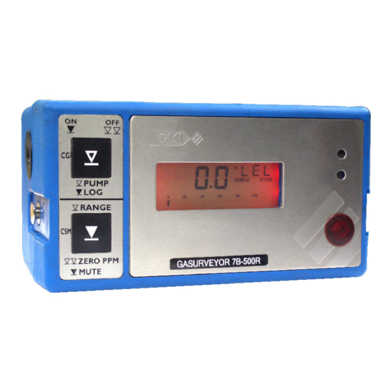
INTRODUCTION The Gasurveyor 7B-500R is a two button portable gas detector which is designed to provide measurement of LEL and Volume flammable gas for leak detection and general safety monitoring. Fig. 1-1 Gasurveyor 7B-500R The Gasurveyor 7B-500R also: • Features a parts per million (ppm) flammable range for increased sensitivity to smaller leaks. - Page 12 GASURVEYOR 7B-500R - USER HANDBOOK The Gasurveyor 7B-500R includes the following ranges: • 0 - 1000 ppm Methane • 0 - 100% LEL • 0 - 100% Volume Gas • 0 - 1000 ppm Carbon Monoxide • 0 - 25% Oxygen...
-
Page 13: General Information
GENERAL INFORMATION The Gasurveyor 7B-500R contains two modes of operation: • Combustible Gas Indicator (CGI) • Confined Space Monitoring (CSM) Ranges and features available are mode dependent. Ranges of Operation The instrument calibration gas, Methane, is shown on the instrument service label, as illustrated in Fig. 2-1. -
Page 14: Methane, 0 - 1000 Ppm
GASURVEYOR 7B-500R - USER HANDBOOK Methane, 0 - 1000 ppm (CGI Mode) This range displays the Methane gas reading in parts per million (ppm), up to 999 ppm. When selected, PPM is displayed in the top right corner of the LCD. -
Page 15: Volume Gas, 0 - 100
GENERAL INFORMATION Volume Gas, 0 - 100% (CGI and CSM Modes) This range displays the total volume of flammable gas with respect to air. When selected, GAS is displayed in the top right corner of the LCD. The digital display resolves to 1%. The analogue bar graph follows in 4% steps. -
Page 16: Oxygen, 0 - 25
GASURVEYOR 7B-500R - USER HANDBOOK Oxygen, 0 - 25% (CGI and CSM Modes) This range displays the % Oxygen (O ) content of the sample. When selected, O2 is displayed in the top right corner of the LCD. The digital display resolves to 0.1% O... - Page 17 GENERAL INFORMATION Mode Range Audible Visual L / NL 20ppm 23.5% 19.5% PPM - ‘Geiger’ 20ppm 23.5% 19.5% Fig. 2-7 Alarms Table 1 - The audible ‘Geiger’ alarm, can toggle ON or OFF. By default set to OFF.
-
Page 18: Confidence Signal
See page 3-10 ‘Operator Messages / Fault Flags’ to identify the instrument fault. Datalogging The Gasurveyor 7B-500R has two datalogging functions: automatic and manual. Datalogging is mode dependent, as illustrated in Fig. 2-8. Mode... -
Page 19: Automatic Datalogging
GENERAL INFORMATION Automatic Datalogging The instrument has automatic datalogging enabled in CSM mode and is confirmed by the ‘STORE’ flag being displayed, as illustrated in Fig. 2-9. Fig. 2-9 Automatic Datalogging Enabled Every 60 seconds, the instrument automatically stores the values of all gas ranges, together with time and date. -
Page 20: Batteries
GASURVEYOR 7B-500R - USER HANDBOOK Batteries Rechargeable Battery Pack The GMI rechargeable battery pack provides approximately nine hours operational life, from fully charged, at ambient temperature of 20 C (68 F). An indication of the battery condition is displayed after power on and during warm- up, with status shown as either OK or LO. -
Page 21: Filters
GENERAL INFORMATION Filters The minimum requirement is a cotton particulate filter and a hydrophobic filter. These filters, incorporated in the probe handle assembly, are available from GMI. Filters must be checked at frequent intervals and where appropriate changed to ensure a clean sample path. See Filter Replacement in Chapter 5 OPERATOR MAINTENANCE. - Page 22 GASURVEYOR 7B-500R - USER HANDBOOK 2-10...
-
Page 23: Operation
OPERATION Instrument Features The Gasurveyor 7B-500R front plate features a panel of two operating buttons, a backlit display, a visual alarm LED and an infrared communication port. Button Backlit Infrared Panel Display Communications Port PUMP RANGE GASURVEYOR 7B-500R ZERO PPM... -
Page 24: Button Panel
Each button can have three functions, accessed with either a single press, double press or press and hold. Button function is dependent on the operating mode of the instrument. The Gasurveyor 7B-500R has two operating modes CGI and CSM: •... - Page 25 OPERATION Pump switches on All LCD segments and a beep sounds displayed Software version Instrument type OK or LO at start-up Battery status Alarm Levels Display alternates between gas range and alarm type Calibration Displays due date alternate between test type and ‘DUE’...
-
Page 26: Calibration Date Features
GASURVEYOR 7B-500R - USER HANDBOOK 1 - The alarm levels displayed are mode dependent. See alarms table, Fig. 2-7 for alarm level details. 2 - The service due date is only displayed when the date of the next service is within 1 month of the current date. -
Page 27: Modes Of Operation
OPERATION Service Due: (Alternate Flash) 6th March Fig. 3-5 Service Due Date The service interval is 12 months. If service is overdue, the instrument will automatically switch OFF. Modes of Operation CGI Mode (Combustible Gas Indicator) Alarms are active on the O and CO ranges. -
Page 28: Switching On
GASURVEYOR 7B-500R - USER HANDBOOK Switching ON Press and hold to turn ON the instrument in CGI mode. The pump will switch on and the instrument will go through the warm up sequence. Switching OFF Double press to switch the instrument OFF. -
Page 29: Geiger' Alarm
OPERATION ‘Geiger’ Alarm The ‘Geiger’ style alarm provides an audible indication of the ppm concentration of gas. The ‘Geiger’ audible alarm is initially muted. To activate press and hold . When activated, press again to mute. Zero PPM Range The flammable ppm range can be manually zeroed. To zero, double press . -
Page 30: Csm Mode (Confined Space Monitoring)
GASURVEYOR 7B-500R - USER HANDBOOK CSM Mode (Confined Space Monitoring) Alarms are active for the LEL, O and CO ranges. When an alarm is activated, the instrument display will automatically change to the alarming range. Alarms will be audible, visible and non-latching. There will also be an audible and visual confidence signal (every 8 seconds) to indicate the instrument alarms are operational. -
Page 31: Acknowledge Alarms
OPERATION Acknowledge Alarms A press and hold of will acknowledge an alarm for 60 seconds. Repeat for each active alarm. Automatic Datalogging Automatic datalogging is activated in this mode. ‘STORE’ will be visible on the display, as illustrated in Fig. 3-8. -
Page 32: Operator Messages / Fault Flags
GASURVEYOR 7B-500R - USER HANDBOOK Operator Messages / Fault Flags Various messages can appear on the display to indicate instrument status. ‘SAMPLE’ This indicates that the pump is running and the instrument is sampling. Fast flash when pump is set to Hi-speed. - Page 33 OPERATION ‘BAT’ This indicates that the batteries will soon require recharging. At this point there will be approximately 30 minutes left in the battery pack, although this figure will vary depending on temperature conditions, usage etc. ‘BAT FAULT’ This indicates that the battery pack should be recharged or replaced immediately.
- Page 34 GASURVEYOR 7B-500R - USER HANDBOOK 3-12...
-
Page 35: Probes
PROBES The Gasurveyor 7B-500R instrument is equipped to accept the following probes and associated accessories: Standard Probe and Handle Assembly Part No. Description 13427 35cm (14ins.) Plastic Probe - Open End 12481 Probe Handle Assembly - incl. filters 12712 Clear Sample Line x 1.5m (4ft 10ins.) approx. -
Page 36: Extended Survey Probe (Optional)
GASURVEYOR 7B-500R - USER HANDBOOK Extended Survey Probe (Optional) - Part No. 42800 Part No. Description 42764 Extended PPM Probe Handle Assembly 42765 PPM Probe Filter & Tubing Assembly 42648 Probe Handle Mid. PPM Gasurveyor Assembly 13655 Swan Neck Probe c/w Shroud... -
Page 37: Operator Maintenance
OPERATOR MAINTENANCE Recharging the Battery Pack The battery pack should be recharged in the following situations: • ‘BAT’ or ‘BAT FAULT’ message is displayed. • The instrument will not switch on. • The pump will not switch on. • When not in use. It is recommended that the battery pack is fully discharged on a regular basis (once every three months). - Page 38 GASURVEYOR 7B-500R - USER HANDBOOK Fig. 5-1 Loosen Instrument Base Screws 2. Remove the battery pack. Fig. 5-2 Remove Battery Pack 3. Insert new battery pack. 4. Fasten base screws. 5. Check the instrument switches on and works to specification.
-
Page 39: Probe Filter Replacement
OPERATOR MAINTENANCE Probe Filter Replacement Probe Handle Assembly - Part No. 12481 Hydrophobic and cotton particulate filters in the probe handle minimise water and dust ingress. Caution: The instrument should never be switched on without suitable filters installed. If a blockage occurs the ‘SAMPLE FAULT’ indicator is displayed. -
Page 40: Probe Handle Assembly (Option) Part No. 13561
GASURVEYOR 7B-500R - USER HANDBOOK 2. Remove the cotton particulate filter and discard. 3. Remove the hydrophobic filter. 4. Clean the probe handle to make sure that it is free from dirt and water. 5. Fit a new cotton particulate filter. -
Page 41: In-Line Dust Filter (Accessory)
OPERATOR MAINTENANCE If a blockage occurs the ‘SAMPLE FAULT’ indicator is displayed. Check the sample line and filter assembly for blockage. Press to clear the ‘SAMPLE FAULT’ message. Replace the filter if the message does not clear. In-line Dust Filter (Accessory) To replace the Dust Filter in the Dust Filter Housing Assembly, proceed as follows: 1. -
Page 42: In-Line Water Filter (Accessory)
GASURVEYOR 7B-500R - USER HANDBOOK In-line Water Filter (Accessory) To replace the Hydrophobic Filter in the Water Filter Housing Assembly, proceed as follows: 1. Unscrew the Filter Housing Assembly (Fig. 5-6). Water Filter Housing Assembly Hydrophobic Filter Probe Sealing Washer... -
Page 43: Flue Probe Coalescing Filter Assembly
OPERATOR MAINTENANCE Flue Probe Coalescing Filter Assembly (Accessory) - Part No. 42215 A coalescing filter is fitted in the filter bowl and housing assembly to minimise water ingress. Caution: The instrument should never be switched on without suitable filters installed. If a blockage occurs the ‘SAMPLE FAULT’... - Page 44 GASURVEYOR 7B-500R - USER HANDBOOK 2. Unscrew the spindle from the filter housing then remove and discard the coalescing filter. 3. Using a dry cloth, clean the bowl, housing and spindle to make sure that they are free from dirt and water.
-
Page 45: Calibration
CALIBRATION The instrument has been calibrated for a particular flammable gas mixture. Where any doubt exists the instrument should be returned to GMI or an authorised distributor for calibration. Three methods of calibration are available: • Automatic Calibration. The GMI Gas Delivery Unit (GDU) allows full automatic calibration. -
Page 46: Calibration Validity
12 month period can be expected. This is no guarantee, however, as the precise application of the product is unknown to Teledyne GMI. Individual codes of practice may dictate shorter periods. Regular checking establishes a pattern of reliability and enables the calibration check to be modified in line with operational experience. -
Page 47: Accessories
ACCESSORIES Accessories supplied with the Gasurveyor 7B-500R instrument (part number: 942507BR) are as follows: Part Number Description 12370 Carrying Harness 12451 Hex Driver (for base screws) 10077 Cotton Particulate Filters (Box of 10) x 2 12712 Sample Line Tubing 1.5m (4ft 10ins.) - Page 48 Dust Filter - Box of 20 (Use with 42184) 12379 Probe Sealing Washer (Use with 42183, 42184) 42235 Probe Washer (Use with 42183, 42184) Note: For other sampling probes and accessories, and for calibration gases, contact Teledyne GMI Ltd or a Teledyne GMI approved distributor.
-
Page 49: Additional Information
ADDITIONAL INFORMATION Training Training Courses are available on all GMI products. Contact GMI Product Support Department for further details: Tel: +44 (0) 141 812 3211 e-mail: gmi_sales@teledyne.com World Wide Web Visit Teledyne GMI web site at: www.teledynegasandflamedetection.com... - Page 50 GASURVEYOR 7B-500R - USER HANDBOOK...
-
Page 51: Typical Operating Parameters
TYPICAL OPERATING PARAMETERS Typical operating parameters are as follows: Range Resolution Zero Accuracy 0 to 1000 ppm 5 ppm +/- 30 ppm 5% +/- 25 ppm 0 to 10% 0.1% +/- 0.5% 2% +/- 1% LEL 10 to 100% 0 to 5% 0.1% +/- 2% 1% +/- 1% Gas... - Page 52 GASURVEYOR 7B-500R - USER HANDBOOK Construction Moulded polypropylene case protected to IP54 Display LCD containing: Analogue display scaled 0 - 10, 0 - 100, 0 - 1000, 0 - 10000 4 digit digital display 3 character range indication Operational flags...
-
Page 53: Applications
APPLICATIONS Small Plastic (Solid End) Probe This probe is available as an accessory. The solid end probe is designed for use with BarHole probing and below ground surface gas monitoring. Holes up the sides of the probe try to prevent water being drawn into the instrument and the clear sample line also shows if water is being drawn. - Page 54 GASURVEYOR 7B-500R - USER HANDBOOK The solid end feature prevents blocking of the probe when detecting gas leaks in soft earth. The Plastic Probe (Part No. 12480) is generally used with the Probe Handle Assembly (Part No. 12481), incorporating both Cotton and Hydrophobic Filters to prevent the ingress of water or dirt.
-
Page 55: Bellows Probe
APPLICATIONS Bellows Probe This probe is available as an accessory. The Bellows probe (Part No. 13563) provides a method of obtaining more consistent readings by reducing the effect of wind and air dilution. Fig. B-2 Bellows Probe The Bellows Probe is of stainless steel construction housed in a flexible rubber boot. -
Page 56: Swan Neck Probe
GASURVEYOR 7B-500R - USER HANDBOOK Note: This model of Probe Handle does not incorporate an in-line filter. A Water Filter Assembly (Part No. 42183) or Dust Filter Assembly (Part No. 42184) are available and can be fitted as an accessory, if required. - Page 57 APPLICATIONS The Swan Neck Probe (Part No. 13655) has a number of small balanced holes in the probe length to give increased coverage in surveys. To prevent damage to the probe and provide an unrestricted sample path, the probe is supplied with a shroud assembly incorporating two skids which prevent probe contact with the ground surface.
-
Page 58: Stainless Steel (Flue) Probe
GASURVEYOR 7B-500R - USER HANDBOOK Stainless Steel (Flue) Probe This probe is also available as an accessory. Fig. B-4 Flue Probe When a flue sample is required, a Stainless Steel Open Ended Probe (Part No. 13413) with Coalescing Filter Assembly (Part No. 42215), incorporating Coalescing Filter (Part No. -
Page 59: Index
INDEX Symbols 3-11 Calibration -EEE 3-11 Calibration Date Features Calibration interval Calibration Validity Accessories Carbon Monoxide, Acknowledge Alarms 0 - 1000 ppm Additional Information CGI Button Operation Alarm levels CGI Mode (Combustible Alarms Gas Indicator) Alarms Table CHECK ZERO 3-10 Applications CO Alarm Indication Areas of Use... - Page 60 GASURVEYOR 7B-500R - USER HANDBOOK EEEE 3-11 LEL, 0 - 100% Extended Survey Probe 4-2 Liability Liquid Crystal Display (LCD) Filter Assembly Filters Flue Probe Coalescing Manual Calibration Filter Assembly Manual Datalogging 2-7, 3-7, 3-9 Methane, 0 - 1000 ppm 2-2...
- Page 61 INDEX Stainless Steel (Flue) Probe Plastic (Solid End) Standard Probe and Probe Handle Assembly Power Source Storage, Handling and Probe Filter Replacement Transit STORE 2-7, 3-11 Probe Handle Assembly 5-3 Swan Neck Probe 4-2, B-4 Probes Switching OFF 3-6, 3-8 Pump Operation 3-6, 3-8 Switching ON...
- Page 62 GASURVEYOR 7B-500R - USER HANDBOOK...
- Page 64 Head Office Inchinnan Business Park Renfrew Scotland PA4 9RG Tel: +44 (0)141 812 3211 gmi_sales@teledyne.com www.teledynegasandflamedetection.com Service & Calibration Centre 25 Cochran Close Crownhill Milton Keynes MK8 0AJ Tel: +44 (0)1908 568 867 gmi_service@teledyne.com Service & Sales - USA 14880 Skinner Road...
Need help?
Do you have a question about the Gasurveyor 7B-500R and is the answer not in the manual?
Questions and answers