
Related Manuals for Teledyne Gasurveyor 700


Summary of Contents for Teledyne Gasurveyor 700
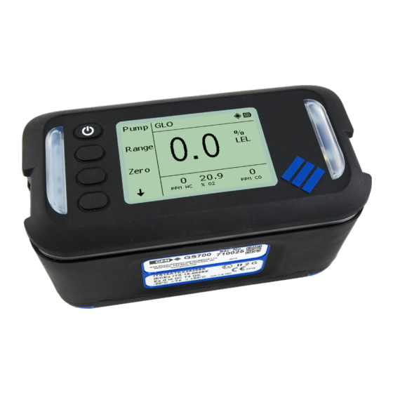
- Page 1 User Manual Gasurveyor 700 IR gas detector with Natural Gas discrimination 49391 Revision 3...
- Page 2 Pipeline Gas Test function is for indication and advisory purposes only and should not be relied upon as the sole indicator for confirming the type of gas present in the environment. Teledyne GMI shall not therefore be held liable for any direct costs or consequential costs, losses or expenses incurred by the user whilst solely relying on a Pipeline Gas Test function in order to determine the presence of piped natural gas.
- Page 3 Gasurveyor 700 USER MANUAL SOFTWARE Any software supplied must only be used in this product and may not be copied without the written permission of the Company. Reproduction or disassembly of such embodied programs or algorithms is prohibited. Ownership of such software is not transferable, and the Company does not warrant that the operation of the software will be error free or that the software will meet the customer’s...
-
Page 4: Table Of Contents
Gasurveyor 700 USER MANUAL Table of Contents About This Guide ........................8 1.1. Guide Conventions ........................8 1.2. Safety ............................8 1.2.1. Additional Safety Requirement - CSA Only ..............9 1.2.2. Certifications And Approvals ..................10 1.2.3. Batteries ..........................10 1.2.4. Equipment Parameters ...................... 1 1 Introduction ..........................12... - Page 5 Gasurveyor 700 USER MANUAL 4.2. Confined Space Monitor (CSM) ..................27 4.2.1. Available Ranges ......................28 4.2.2. Features ..........................28 4.2.3. Display ..........................28 4.2.4. Soft-keys Functions ......................28 4.2.5. Logging ..........................28 4.2.6. Gas Readings & Alarm Set-points Viewer ..............
- Page 6 Gasurveyor 700 USER MANUAL 6.2. Recharging the Battery Pack....................42 6.2.1. Charging the Monitor ...................... 43 6.2.2. Replacing / Charging the Battery Pack ................. 44 6.3. Cleaning ..........................45 6.4. Replacing the Filters ......................45 6.4.1. Probe Handle Filter Replacement ...................
- Page 7 Gasurveyor 700 USER MANUAL Page intentionally left blank. 49391 Revision 3...
-
Page 8: About This Guide
USER MANUAL 1. About This Guide This guide instructs gas detection personnel on the features and usage of the Gasurveyor 700 (or “the monitor”). It also provides information on configuration, operation, maintenance, specifications and trouble shooting. This user guide assumes the reader has a basic knowledge of gas detection procedures. -
Page 9: Additional Safety Requirement - Csa Only
Gasurveyor 700 USER MANUAL WARNING: TO REDUCE THE RISK OF IGNITION OF A FLAMMABLE OR EXPLOSIVE ATMOSPHERE, BATTERIES MUST BE CHANGED ONLY IN A LOCATION KNOWN TO BE NON-HAZARDOUS. WARNING: TO REDUCE RISK OF EXPLOSION, DO NOT MIX OLD BATTERIES WITH USED BATTERIES OR MIX BATTERIES FROM DIFFERENT MANUFACTURERS. -
Page 10: Certifications And Approvals
Gasurveyor 700 USER MANUAL Note: CSA have only assessed the LEL combustible gas detection portion of this monitor for performance. Note: CSA a seulement évalué la partie LIE pour la mesure des performances en détection de gaz inflammables. Note: The monitor performs internal checking of sensor sensitivity, which during calibration will prevent the sensor being calibrated if it has been contaminated or reached its end of life. -
Page 11: Equipment Parameters
Gasurveyor 700 USER MANUAL Caution: Only use the following approved size ‘D’ (LR20) alkaline batteries: • ANSMANN: Industrial or X-Power • DURACELL: Industrial or Procell • PANASONIC: Evolta CAUTION: Remove batteries if the monitor will be stored for longer than 3 months. -
Page 12: Introduction
USER MANUAL 2. Introduction 2.1. Monitor Overview The Gasurveyor 700 (GS700) is the first choice for all gas utility applications. Reliable measurements are performed using innovative infrared sensing technology including instantaneous confirmation that the gas sample is natural gas. This lightweight, rugged instrument is easy to use thanks to an intuitive menu layout on a large display. -
Page 13: Modes Of Operation
Gasurveyor 700 USER MANUAL 2.4. Modes of Operation Used by technicians to investigate outdoor odour or leak Gas Leak Outdoors complaints and to pinpoint leaks. This mode supports the optional (GLO) Barhole feature. Gas Leak Indoors Similar to the GLO mode, but without Barhole testing. -
Page 14: Display
Gasurveyor 700 USER MANUAL Visual Alarm Visual Alarm Soft Keys Display Figure 3: GS700 - Top View 2.6. Display The GS700 is a fully configurable gas monitor and menu structure or information displayed may vary. Status Bar Gas Readings /... -
Page 15: Status Bar
Gasurveyor 700 USER MANUAL 2.6.2 Status Bar This area of the screen informs the user of the current operating mode and displays icons that provide information about monitor status. Status Bar Figure 6: Status Bar Status bar icons: Battery Current battery level. -
Page 16: Operation
Gasurveyor 700 USER MANUAL 3. Operation 3.1. Operating Procedure Check the following before use: • The monitor is clean and in good condition. • The inlet filter is clean and in good condition. • The sample line and any other accessories to be used are in good condition. -
Page 17: Monitor Identification
Gasurveyor 700 USER MANUAL Figure 8: Splash Screen 3.3.1 Monitor Identification During warm-up, the serial number, software version and battery status information are listed, as shown in Figure 9: Warm-up - Monitor Figure 9: Warm-up - Monitor ID 3.3.2 Date & Time... -
Page 18: Calibration And Service Due Dates
Gasurveyor 700 USER MANUAL 4. Bump Due enabled - if overdue, user acknowledge is required. As shown in Figure 1 1: Warm-up - Bump Overdue. If bump is due, the user must either: • Press Continue for monitor warm-up to continue. -
Page 19: Soundness Test
Gasurveyor 700 USER MANUAL 5. Calibration / Service Due enabled - if overdue, user can extend the due date by up to 30 days. If calibration or service is within the “extended period”, the user must still acknowledge that calibration has expired as shown in Figure 12: Warm-up - Calibration Overdue. -
Page 20: Alarm Levels
Gasurveyor 700 USER MANUAL Figure 16: Soundness Test Fail 3.3.6 Alarm Levels After the Soundness Test is successfully completed, the monitor will report the alarm set-points for each range (e.g. LEL range shown in Figure 17: Warm-up - Alarm set-points (LEL)). -
Page 21: Sensors Zero Check
If a Zero Fault is detected, the monitor should be restarted in fresh air. If the fault persists, recalibrate the monitor. If that fails, return the monitor to a Teledyne GMI approved service center. Note: If a Zero Fault exists, the monitor can still be used to detect and alarm on all the other ranges fitted. -
Page 22: Modes Of Operation
Gasurveyor 700 USER MANUAL 4. Modes of Operation During monitor procurement, the GS700 can be configured to have up to 4 of the following modes of operation: • Gas Leak Outdoors (GLO) - with optional Barhole testing • Gas Leak Indoors (GLI) •... -
Page 23: Gas Leak Outdoors / Indoors
Gasurveyor 700 USER MANUAL Note: Some of the ranges, features and functions described below are optional and may not be available on your monitor. 4.1. Gas Leak Outdoors (GLO) / Indoors (GLI) In these modes, the GS700 acts as a gas indicator drawing a gas sample, via a probe, where gas is suspected to be present. -
Page 24: Soft-Keys Functions
Gasurveyor 700 USER MANUAL 4.1.4 Soft-keys Functions Button Action Switch the pump ON/OFF. Monitor functionality is disabled when the pump is OFF (as shown in Figure 25: Pump OFF). Pump Figure 25: Pump OFF Zero Zero all gas ranges. Enter Barhole mode. -
Page 25: Barhole Testing
Gasurveyor 700 USER MANUAL 4.1.6 Barhole Testing Barhole testing is available only in Gas Leak Outdoors (GLO) mode. Barholes are small holes, inserted in the ground to assist with pin-pointing a gas leak from an underground gas pipe. Readings are obtained by placing a probe into the barhole. - Page 26 Gasurveyor 700 USER MANUAL Figure 29: Barhole - Screen 2 Figure 30: Barhole - Screen 3 4. Press Start button to initiate barhole test. Press + or - buttons to browse the barhole numbers. Press Quit button to return to Gas Leak Outdoor (GLO) main screen.
-
Page 27: Confined Space Monitor (Csm)
Gasurveyor 700 USER MANUAL 6. After sampling is complete, there is a purge that removes any residual gas from the monitor before the next barhole can be sampled. Press Purge button to initiate the purge process. Press + or - buttons to view the results of other barhole tests. -
Page 28: Available Ranges
Gasurveyor 700 USER MANUAL 4.2.1 Available Ranges • 0 - 100% LEL Flammable • 0 - 25% Volume Oxygen (O • 0 - 1,000 ppm Carbon Monoxide (CO) • 0 - 100 ppm Hydrogen Sulphide (H 4.2.2 Features Confined Space Monitor mode features: •... -
Page 29: Gas Readings & Alarm Set-Points Viewer
Gasurveyor 700 USER MANUAL 4.2.6 Gas Readings & Alarm Set-points Viewer In CSM mode, the monitor records the maximum (Max) and minimum (Min) gas values, as well as the short-term (STEL) and long-term (LTEL) exposures for CO and H To view the recorded values: 1. -
Page 30: Features
Gasurveyor 700 USER MANUAL 4.3.2 Features Purge mode features: • Audible / visual alarms for oxygen range (optional) • Pump control • Manual & automatic datalogging • Sensor zeroing 4.3.3 Display Figure 37: Typical Purge display 4.3.4 Soft-keys Functions Button Action Switch the pump ON/OFF. -
Page 31: Logging
Gasurveyor 700 USER MANUAL Change the gas ranges visible on the main section of the display (as shown in Figure 39: Change Range). Range Figure 39: Change Range CAUTION: Always zero the monitor in clean atmosphere. 4.3.5 Logging By default, automatic datalogging every minute is active for all ranges. -
Page 32: Display
Gasurveyor 700 USER MANUAL 4.4.3 Display Figure 40: Typical Search display 4.4.4 Soft-keys Functions Button Action Toggle the pump between normal speed / high speed / OFF. Monitor functionality is disabled when the pump is OFF (as shown in Figure 41: Pump OFF). -
Page 33: Logging
Gasurveyor 700 USER MANUAL CAUTION: Always zero the monitor in fresh air. 4.4.5 Logging By default, automatic datalogging is active and being performed every 4 seconds. 4.5. Pipeline Gas Test (PGT) Pipeline Gas Test is used to discriminate between methane and other hydrocarbons. It can quickly determine if the source of gas leaks is from pipeline gas or is naturally occurring biogas. - Page 34 Gasurveyor 700 USER MANUAL CAUTION: Always zero the monitor in clean atmosphere. 3. After the monitor has made a discrimination, the decision is displayed as shown in Figure 44: Discrimination. Figure 44: PGT Sampling Note: The ’Methane Only!’ and ‘Other Hydrocarbons’ messages can be changed during the monitor procurement.
-
Page 35: Alarms
Gasurveyor 700 USER MANUAL 5. Alarms Alarm set-points (instantaneous, STEL and LTEL) are set during the monitor procurement. It is important to verify that the set-points are in accordance with your company’s requirements and with local health and safety legislation. -
Page 36: Time-Averaged Toxic Gas Alarms
Gasurveyor 700 USER MANUAL 5.2. Time-averaged Toxic Gas Alarms In the Confined Space Monitor (CSM) mode the monitor also calculates the Short-Term and Long- Term Exposures for toxic gas ranges. If these exceed the STEL or LTEL then alarms are activated. -
Page 37: Gas Alarm Options
Gasurveyor 700 USER MANUAL Figure 48: HIHI LEL Alarm Figure 49: STEL H S Alarm Figure 50: LTEL CO Alarm 5.6. Gas Alarm Options 5.6.1 Alarm Intensity In Gas Leak Indoors, Gas Leak Outdoors and Purge modes user can choose different intensities for the instantaneous alarms. -
Page 38: Latching / Non Latching
Gasurveyor 700 USER MANUAL Note: In Confined Space Monitor (CSM) mode alarms are always set to high intensity. 5.6.2 Latching / Non Latching In Confined Space Monitor (CSM) mode alarms are individually programmable to be either latching or non-latching: • Latching - alarms can only be reset once gas readings have returned to a safe level. To reset, press and hold the Ack button. -
Page 39: Over-Range Alarm
Gasurveyor 700 USER MANUAL 5.7.3 Over-range Alarm In the event of the flammable gas sensor being exposed to a high concentration of flammable gas, the instrument has an over-range alarm. • In Confined Space Monitor (CSM) mode if the LEL sensor is exposed to gas above 100%... -
Page 40: Sample Fault
Gasurveyor 700 USER MANUAL 5.7.5 Sample Fault If a sample fault exists: • Monitor functionality is disabled and ‘Sample fault’ flashes on screen (as shown in Figure 55: Sample Fault). • Audible alarm activates. • Top cover LED flash. • Red display backlight activates. -
Page 41: Operator Maintenance
Gasurveyor 700 USER MANUAL 6. Operator Maintenance 6.1. Replacing Alkaline Batteries WARNING: BATTERIES MUST BE CHANGED ONLY IN A LOCATION KNOWN TO BE NON-HAZARDOUS. WARNING: DO NOT MIX NEW BATTERIES WITH USED BATTERIES OR MIX BATTERIES FROM DIFFERENT MANUFACTURERS. WARNING: DO NOT USE RECHARGEABLE BATTERIES. -
Page 42: Recharging The Battery Pack
6. Replace battery cover and fasten the base screws. 6.2. Recharging the Battery Pack The Lithium-Ion battery pack is recharged using a dedicated Teledyne GMI charger. The battery pack can be charged fitted to the monitor or separately. Power LED... -
Page 43: Charging The Monitor
Gasurveyor 700 USER MANUAL 6.2.1 Charging the Monitor 1. Ensure the monitor is switched OFF and charger is switched ON (indicated by the green power LED). 2. Place the monitor into the charging cradle, as shown in Figure 60: Monitor Charging. -
Page 44: Replacing / Charging The Battery Pack
Gasurveyor 700 USER MANUAL 6.2.2 Replacing / Charging the Battery Pack 1. Using the 4mm hex driver (supplied), loosen the 2 base screws and remove the battery pack. Figure 64: Battery Pack Removal 2. Remove the battery pack. Figure 65: Removed Battery Pack 3. -
Page 45: Cleaning
Gasurveyor 700 USER MANUAL Figure 67: Battery pack LED 6. Once charged, remove the battery pack from charger, as shown in Figure 68: Battery Pack Charging. Figure 68: Battery Pack Charging 7. Re-fit the battery pack to the monitor and fasten the base screws. -
Page 46: Probe Handle Filter Replacement
Gasurveyor 700 USER MANUAL 6.4.1 Probe Handle Filter Replacement Hydrophobic and cotton particulate filters in the probe handle minimise the ingress of water and dust. Note: When replacing the hydrophobic filter, you must also replace the dust filter. To replace the filter(s): 1. -
Page 47: Screen Contrast Adjustment
Gasurveyor 700 USER MANUAL 2. Remove the dust filter from the inlet nozzle. Dust Filter Inlet Nozzle Figure 71: Inlet Nozzle 3. Clean the inlet nozzle to make sure it’s free from dirt and water. 4. Fit a new dust filter into the inlet nozzle. -
Page 48: Bump Test
Gasurveyor 700 USER MANUAL 7. Bump Test A bump test verifies sensor response and alarm operation by exposing the monitor to a known concentration of gas. There are three bump test options: • Manual (LEL-only test) - using the monitor’s Bump Test feature (recorded in the instrument’s datalogger to meet CSA requirements) •... - Page 49 Gasurveyor 700 USER MANUAL 3. Connect the calibration gas to the monitor inlet (as shown in Figure 75: Connect Calibration Gas). Figure 75: Connect Calibration Gas Note: Calibration gas shall be delivered to the monitor at ambient pressure. Application of pressurised mixture will result in ‘Sample Fault’ alarm. Use of a On-Demand Flow Regulator is recommended.
-
Page 50: Manual Bump Test (All Ranges)
Gasurveyor 700 USER MANUAL 5. Disconnect the calibration gas from the monitor. When the gas concentration drops below 10% LEL, the monitor returns to the normal operating screen. CAUTION: The infrared sensor fitted in the GS700 is used for measuring all three flammable gas ranges: ppm, LEL and Volume. -
Page 51: Automatic Bump Test
Gasurveyor 700 USER MANUAL Figure 81: Bump Test - Purge Note: The following gas concentrations are suggested if no other requirements are specified by local regulations and/or internal company procedures: • Flammable ppm 4550ppm • Flammable %LEL 50% LEL •... -
Page 52: Calibration
However this is not guaranteed, as the precise application of the product is unknown to Teledyne GMI. Individual codes of practice may dictate shorter periods. Regular checking establishes a pattern of reliability and enables the calibration check to be modified in line with operational experience. - Page 53 Gasurveyor 700 USER MANUAL 2. After the monitor warm-up is completed, if prompted, enter the field calibration code. The default code is 4343 (B4, B3, B4, B3). Figure 84: Field Calibration Code Note: The 4 digit field calibration code can be selected during monitor procurement.
- Page 54 Gasurveyor 700 USER MANUAL 7. If the displayed reading does not match the concentration of the calibration gas, correct by pressing the appropriate soft-key. Press + button to increase the reading Press - button to decrease reading Figure 88: Field Calibration - Adjustment Figure 89: Field Calibration - Completed Adjustment 8.
-
Page 55: Manual Calibration
Gasurveyor 700 USER MANUAL 8.3. Manual Calibration Teledyne GMI’s FlexiCal Plus software facilitates manual calibration by: • Setting up of the calibration test. • Step by step instruction during calibration. • Storage of test results files. Manual calibration requires the user to control the delivery of gas during calibration. -
Page 56: Accessories
9.3. Software Part No. Description 48151 FlexiCal Plus Package (CD + IR Adaptor) 48365 Spare IR Adaptor Note: For a comprehensive list of spare parts, probes, accessories and calibration gases, contact your local distributor or alternatively, Teledyne GMI. 49391 Revision 3... -
Page 57: Monitor Specifications
Gasurveyor 700 USER MANUAL 10. Monitor Specifications Range Resolution Sensor Type 0-10,000ppm 1ppm Semiconductor Flammable 0-10,000ppm 25ppm Infrared 0 to 9.9% LEL 0.1% Flammable Infrared 10 to 100% LEL 0 to 5% Volume 0.1% Flammable Infrared 5 to 100% Volume 0 to 20.9%... - Page 58 Gasurveyor 700 USER MANUAL Other Specifications 500 session logs, each log can include: • Date & time • Modes of operation • Gas readings Datalogging: • Activated alarms • Calibration & Bump data • Barhole logs • GPS location data Oldest logs will be overwritten when full.
-
Page 59: Technical Support
Gasurveyor 700 USER MANUAL 11. Technical Support This product is designed to provide you with reliable, trouble-free service. Contact your regional technical support if you have technical questions, need support, or if you need to return a product. Details can be found at: www.teledynegasandflamedetection.com... -
Page 60: Appendix A: Pipeline Gas Test (Pre Firmware V1.30)
Gasurveyor 700 USER MANUAL Appendix A: Pipeline Gas Test (pre firmware v1.30) The pipeline gas test is used to discriminate between pipeline gas (natural gas) and non pipeline gas (e.g. landfill or swamp gas). Note: The pipeline gas test, when configured, can run in the background of ALL modes of operation, except for CSM. - Page 61 Gasurveyor 700 USER MANUAL Page intentionally left blank. 49391 Revision 3...
- Page 62 AMERICAS EMEA ASIA PACIFIC 14880 Skinner Road Inchinnan Business Park 750C Chai Chee Road Cypress, Renfrew, PA4, 9RG #03-08 Viva Business Park TX 77249, USA Scotland, UK Singapore 469003 Tel: +1-713-559-9200 Tel.: +44 (0) 141 812 321 1 Tel.: +65 84282741 www.teledynegasandflamedetection.com 49391 Revision 3...
Need help?
Do you have a question about the Gasurveyor 700 and is the answer not in the manual?
Questions and answers