Table of Contents
Advertisement
Quick Links
Advertisement
Table of Contents

Related Manuals for Teledyne Everywhereyoulook GT-FIRE


Summary of Contents for Teledyne Everywhereyoulook GT-FIRE
- Page 1 User Manual GT-FIRE PORTABLE GAS DETECTOR 67816 Revision D...
- Page 2 LEGAL STATEMENT Teledyne, the Teledyne Logo, Gas Measurement Instruments, GMI and GT-Fire are registered and/or unregistered marks of Teledyne Gas Measurement Instruments Ltd, also referred to as “the Company.” All rights reserved. No part of this documentation may be reproduced in any form or by any means or used to make any derivative work (such as translation, transformation, or adaptation) without written permission from the Company.
- Page 3 GT-FIRE PORTABLE GAS DETECTOR DISPOSAL ADVICE Dispose of the monitor carefully and with respect for the environment. If returned, the Company will dispose of the monitor without charge. AREAS OF USE Exposure to certain chemicals can result in a loss of sensitivity of the flammable sensor. Where such environments are known or suspected, it is recommended that more frequent response checks are carried out.
-
Page 4: Table Of Contents
GT-FIRE PORTABLE GAS DETECTOR Table of Contents About This Guide ........................7 1.1. Guide Conventions ........................7 1.2. Safety ............................7 1.2.1. Additional Safety Requirement - CSA Only ..............8 1.2.2. Certifications And Approvals .....................8 1.2.3. Batteries ..........................8 1.3. Storage, Handling and Transit ....................9 Introduction .......................... - Page 5 GT-FIRE PORTABLE GAS DETECTOR 4.2.2. Features ..........................21 4.2.3. Display ..........................21 4.2.4. Pump ..........................21 4.2.5. Button Operation ......................22 4.2.6. Logging ..........................22 4.2.7 Confidence Signal ......................23 Alarms ............................24 5.1. Instantaneous Gas Alarms ....................24 5.2. Time-Averaged Toxic Gas Alarms ..................
- Page 6 GT-FIRE PORTABLE GAS DETECTOR 9.1. Consumables ........................46 9.2. Accessories .......................... 46 9.3. Spare Parts ........................... 47 9.4. Software ..........................47 Monitor Specifications ......................48 Technical Support ........................49 67816 Revision D...
-
Page 7: About This Guide
GT-FIRE PORTABLE GAS DETECTOR 1. About This Guide This guide instructs gas detection personnel on the features and usage of the GT-Fire gas detectors (or “the monitor”). It also provides information on configuration, operation, maintenance, specifications and trouble shooting. This user guide assumes the reader has a basic knowledge of gas detection procedures. -
Page 8: Additional Safety Requirement - Csa Only
GT-FIRE PORTABLE GAS DETECTOR WARNING: TO REDUCE RISK OF EXPLOSION, DO NOT MIX OLD BATTERIES WITH USED BATTERIES OR MIX BATTERIES FROM DIFFERENT MANUFACTURERS. WARNING: NEVER ATTEMPT TO RECHARGE NON-RECHARGEABLE CELLS. Caution: Not for use in oxygen enriched atmospheres. 1.2.1. Additional Safety Requirements - CSA Only Caution: Before each day’s usage, sensitivity must be tested on a known concentration of Methane equivalent to 25% - 50% of full-scale concentration. -
Page 9: Storage, Handling And Transit
GT-FIRE PORTABLE GAS DETECTOR 1.3. Storage, Handling and Transit • Rechargeable batteries contain energy and care should be taken in their handling and disposal. • Remove batteries if the monitor will be stored for longer than 3 months. • The monitor may contain electrochemical sensors with an expected life of 2 years. Under conditions of prolonged storage, the sensors should be removed. -
Page 10: Introduction
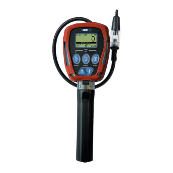
GT-FIRE PORTABLE GAS DETECTOR 2. Introduction 2.1. Monitor Overview The GMI GT-Fire portable gas detector is a multifunction, multi-application gas monitor designed to suit the needs of the fire industry. Figure 1: GT-Fire Portable Gas Detector 2.2. Features • PPM and LEL Methane (CH ) gas ranges •... -
Page 11: Monitor Ranges
GT-FIRE PORTABLE GAS DETECTOR 2.3. Monitor Ranges The following ranges are available in the GT: • 0-2,000 ppm Methane • 0-100% LEL Methane • 0-25% Oxygen (O • 0-1000 ppm Carbon Monoxide (CO) • 0-100 ppm Hydrogen Sulphide (H Note: Your GT-Fire may not have all ranges fitted. Note: The GT-Fire is calibrated for Methane. -
Page 12: Operation
GT-FIRE PORTABLE GAS DETECTOR 3. Operation 3.1. Operation Procedure Check the following before use: • The monitor is clean and in good condition. • The hydrophobic filter is clean and in good condition. • The clear probe filter bulb is screwed tightly and in good condition. •... -
Page 13: Monitor Identification
GT-FIRE PORTABLE GAS DETECTOR 3.3. Monitor Identification During warm-up, the serial number, software version and battery status information are listed, as shown in Figure 3: Monitor Figure 3: Monitor ID 3.4. Filter Check/Flow Fault Test By default, this check is performed daily. This option can be enabled or disabled by the user. 3.4.1. -
Page 14: Time And Date
GT-FIRE PORTABLE GAS DETECTOR 3. Select NEXT to switch the pump ON and continue warm-up cycle. Figure 6: Successful Test If the monitor fails the flow fault test, the screen shown in Figure 5: Flow Fault Test remains displayed. Note: The monitor logs a successful Flow Fault test or if SKIP was selected. 3.5. -
Page 15: Service Due
GT-FIRE PORTABLE GAS DETECTOR 4. Cal Due enabled - if overdue, message is displayed as shown in Figure 9: Calibration Overdue and the user is required to acknowledge the message before continuing the warm-up. Note: This is the default setting. If calibration is due, the user must either: •... -
Page 16: Sensor Zeroing
GT-FIRE PORTABLE GAS DETECTOR 3. Service Due enabled - if overdue, message is displayed as shown in Figure 1 1: Service Due Date, but after five seconds, the monitor warm-up continues automatically. Figure 11: Service Due Date 4. Service Due enabled - if overdue, user acknowledge is required. Figure 12: Service Overdue 5. -
Page 17: Warm-Up Complete
GT-FIRE PORTABLE GAS DETECTOR 3.9. Warm-up Complete The monitor automatically selects the Leak Test mode by default. The monitor can be configured to: 1. Start up in specific mode. 2. Start up in the mode last used. 3.10. Switch the Monitor OFF Note: Allow the monitor to run for 1-2 minutes in fresh air before switching it OFF. -
Page 18: Modes Of Operation
GT-FIRE PORTABLE GAS DETECTOR 4. Modes of Operation 4.1. Leak Test Mode Note: The monitor pump must be switched ON to perform correct measurement in Leak Test mode. This mode is used to investigate odour or leak complaints and pinpoint leaks. 4.1.1. -
Page 19: Button Operation
GT-FIRE PORTABLE GAS DETECTOR Figure 18: Methane + CO 4.1.4. Button Operation Action Button Note Press Invert Display Displays the Maximum readings since the mode was Press and Hold selected. To return to live readings, press and hold again or wait 30 seconds. -
Page 20: Logging
GT-FIRE PORTABLE GAS DETECTOR Action Button Note Audible and visual alarms are enabled when Leak mode is selected. To change alarms: 1st press and hold - visual only. Press and Hold 2nd press and hold - disable both. Ticker (Geiger) 3rd press and hold - enable both. -
Page 21: Features
GT-FIRE PORTABLE GAS DETECTOR 4.2.2. Features Confined Space mode features: • Audible / Visual Alarms • Pump ON continuously (will not stop if flow fault is detected) • Automatic & Manual Datalogging • Max / Min Display • Time weighted averaging (TWA) alarms for toxic ranges •... -
Page 22: Button Operation
GT-FIRE PORTABLE GAS DETECTOR 4.2.5. Button Operation Action Button Note Press Invert Display 1st press and hold - Maximum gas readings since the mode was selected. Press and Hold 2nd press and hold - Minimum O gas reading since Max/Min the mode was selected. -
Page 23: Confidence Signal
GT-FIRE PORTABLE GAS DETECTOR 4.2.7. Confidence Signal Every 15 seconds during normal operation, the monitor emits a confidence beep and briefly illuminates the bottom pair of red LEDs. This informs the user that the monitor is operational and sampling. 67816 Revision D... -
Page 24: Alarms
GT-FIRE PORTABLE GAS DETECTOR 5. Alarms Alarm set-points (instantaneous, STEL and LTEL) are factory set. It is important to verify that the set-points are in accordance with your company’s requirements and with local health and safety legislation. 5.1. Instantaneous Gas Alarms •... -
Page 25: Gas Alarm Examples
GT-FIRE PORTABLE GAS DETECTOR 5.3. Gas Alarm Examples Figure 23: LOLO Oxygen Alarm Figure 24: HIHI LEL Alarm Figure 25: STEL H S Alarm Figure 26: LTEL H S Alarm 5.4. Gas Alarm Options 5.4.1. Latching/Non Latching Alarms are individually programmable to be either latching or non-latching: •... -
Page 26: Muting
GT-FIRE PORTABLE GAS DETECTOR 5.4.3. Muting • Alarms can be individually programmable to be mutable. • This means the audible alarm can be muted for 60 seconds. • After 60 seconds, if the alarm conditions still exist, the alarm will reactivate. •... -
Page 27: Sample / Flow Fault
GT-FIRE PORTABLE GAS DETECTOR • Switch monitor OFF and ON again. Figure 28: Zero Fault • If the fault persists, return the monitor for service. 2. ‘ZERO FAULT’ and a wrench symbol, alternating with a gas reading, as illustrated in Figure 27: Zero Fault (LEL). -
Page 28: Default Alarm Options
GT-FIRE PORTABLE GAS DETECTOR 5.6. Default Alarm Options Audible Visual LED Alarm Type Latching? Mutable? Indication Indication LEL Warning Alarm disabled by default LEL (HI) High Pitch 4x LED Flashing LEL (HIHI) High Pitch 8x LED Ramping (LO) Alarm disabled by default (LOLO) High Pitch 8x LED Ramping... -
Page 29: Operator Maintenance
GT-FIRE PORTABLE GAS DETECTOR 6. Operator Maintenance 6.1. Replacing/Recharging Batteries The monitor’s handle contains three “C” size batteries (see Figure 30: GT-Fire Battery Location). Refer to Section 1.2.3 Batteries for the allowed battery types. Figure 30: GT-Fire Battery Location 6.1.1. Replacing Batteries WARNING: BATTERIES MUST BE CHANGED ONLY IN A LOCATION KNOWN TO BE NON-HAZARDOUS. - Page 30 GT-FIRE PORTABLE GAS DETECTOR 1. Unscrew the captive thumb screw from the battery cover assembly. 2. Press the securing catch to release the battery cover assembly. 3. Remove the cover in direction shown in Figure 31: Battery Cover Removal. Figure 31: Battery Cover Removal 4.
-
Page 31: Charging Batteries
GT-FIRE PORTABLE GAS DETECTOR Figure 33: O-Ring Replacement 7. Reattach all parts (reverse of removal procedure). 6.1.2. Charging Batteries WARNING: NEVER RECHARGE NON RECHARGEABLE CELLS. Caution: Switch the monitor off when charging batteries. There are three options for charging batteries fitted inside the monitor: •... - Page 32 GT-FIRE PORTABLE GAS DETECTOR The green ‘Power’ LED is on during charging. When charging is complete, the screen shown in Figure 35: Charging Complete is displayed. Figure 35: Charging Complete If ‘CHARGING TERMINATED’ is displayed, as shown in Figure 36: Charging Terminated, an excessive charge voltage exists that may have been caused by attempting to charge Alkaline batteries.
- Page 33 GT-FIRE PORTABLE GAS DETECTOR 6.1.2.2. Charging Station The charging station, shown in Figure 38: GT Series Charging Station, will also locate the monitor securely while charging. Refer to Charging Station Instruction Sheet (P/N 67252) for more details. Figure 38: GT Series Charging Station To insert monitor in charging station: 1.
- Page 34 GT-FIRE PORTABLE GAS DETECTOR 2. Ensure the monitor is switched OFF. 3. Locate the hole on the base of the monitor handle and insert onto the charging station, refer to Figure 38: GT Series Charging Station. 4. Secure monitor into the storage clip and engage securing strap, refer to Figure 40: Charging Station - Monitor Location.
-
Page 35: Cleaning
GT-FIRE PORTABLE GAS DETECTOR Figure 41: Charging Station - Monitor Location 6.1.2.3. 12V / 24V Vehicle Charger The 12V / 24V Vehicle Charger (shown in Figure 42: Vehicle Charger Lead) provides the option of charging the monitor from a vehicle cigarette lighter socket. A red LED on the charger plug indicates ‘power on’. -
Page 36: Replacing The Filters
GT-FIRE PORTABLE GAS DETECTOR 6.3. Replacing the Filters The monitor is fitted with dust and hydrophobic filters. These protect the monitor from the ingress of dust and moisture. The filters are located in the probe and must be inspected periodically for contamination or damage. -
Page 37: Hydrophobic Filter
GT-FIRE PORTABLE GAS DETECTOR 6.3.2. Hydrophobic Filter Note: When replacing the hydrophobic filter, you must also replace the dust filter. Caution: The monitor must be OFF when replacing the hydrophobic filter. Ensure any dust / dirt falls away from the monitor. 1. -
Page 38: Chemical Filter (Optional Accessory)
The absorber will change colour from dark purple to brown when saturated and replacement is required. Caution: The contents of this filter must only be replenished with Teledyne GMI approved chemicals. Note: When replacing the chemical filter, you must also replace the dust filter. - Page 39 GT-FIRE PORTABLE GAS DETECTOR 4. If the content of the chemical filter is to be replaced, hold the filter assembly in the upright position, as shown in Figure 46: Filter Housing Adaptor Removal. Unscrew the filter housing adaptor. Figure 46: Filter Housing Adaptor Removal 5.
-
Page 40: Cotton Filter (Optional Accessory)
GT-FIRE PORTABLE GAS DETECTOR Figure 48: Filter Adaptor Removal 7. Fill the filter housing to a level just below the internal threads. Do not overfill. 8. Reattach all parts (reverse of removal procedure). Note: Do not overtighten the probe adapter or chemical filter. 6.3.4. - Page 41 GT-FIRE PORTABLE GAS DETECTOR 1. Using a pencil, push the cotton filter from the threaded end of the housing, as shown in Figure 50: Cotton Filter Removal, then remove it. Figure 50: Cotton Filter Removal 2. Replace the cotton filter if it is contaminated or damaged (part no. 10077). 3.
-
Page 42: Bump Test
GT-FIRE PORTABLE GAS DETECTOR 7. Bump Test A Bump Test verifies sensor response and alarm operation by exposing the monitor to a known concentration of gas. Press and hold both the LH and the RH buttons to enter the mode selection menu and then select ‘BUMP TEST’... - Page 43 GT-FIRE PORTABLE GAS DETECTOR 2. To enter/edit the gas cylinder concentration, press and hold the NEXT button to highlight the gas value to be altered (as shown in Figure 54: Enter/Edit CalGas Value). Press the UP DOWN buttons as necessary to enter the correct gas value. Note: Pressing and holding either of the buttons will rapidly increase/decrease the gas value.
-
Page 44: Viewing Bump Test Results
GT-FIRE PORTABLE GAS DETECTOR 7.2. Viewing Bump Test Results From CalGas set-up screen (shown in Figure 53: Example CalGas Cylinder), press and hold LAST button to view the results of the last 32 bump tests. The screen shown in Figure 57: Previously Stored Bump Tests will be displayed. -
Page 45: Calibration
GTCAL Software User Handbook (Part no. 67244) for further details. Note: For further information on calibration options, please contact Teledyne GMI or an authorized distributor. 8.1. Calibration Validity Calibration validity remains the responsibility of the user. Individual codes of practice may dictate calibration intervals. -
Page 46: Accessories
GT-FIRE PORTABLE GAS DETECTOR 9. Accessories Accessories and spare parts available for the GT-Fire monitors are as follows: 9.1. Consumables Part No. Description 67163 Dust Filter - Box of 30 67196 Cotton Filter 10077 Cotton Filter - Box of 10 (use with 67196) 67138 Filter Disc - Filter Housing (use with 67142) 67199... -
Page 47: Spare Parts
Part No. Description 67238 GTCAL System Package (including CD and interface) 67164 GT Data Downloading Package (including CD and interface) For a comprehensive list of probes, accessories and calibration gases, contact your local distributor or alternatively, Teledyne GMI. 67816 Revision D... -
Page 48: Monitor Specifications
GT-FIRE PORTABLE GAS DETECTOR Appendix A. Monitor Specifications Range Span Resolution Sensor Type Methane (CH ) ppm 0-2000ppm 1ppm Semiconductor 0 to 100% Methane (CH ) LEL Catalytic Bead 0 to 9.9% 0.1% Oxygen (O 0 to 25% 0.1% Electrochemical Carbon Monoxide (CO) 0 to 1000ppm 1ppm... -
Page 49: Technical Support
GT-FIRE PORTABLE GAS DETECTOR Appendix B. Technical Support This product is designed to provide you with reliable, trouble-free service. Contact your regional technical support if you have technical questions, need support, or if you need to return a product. Details can be found at: www.teledynegasandflamedetection.com Note: When returning a product, contact Technical Support to obtain a Return Material Authorization (RMA) number prior to shipping. - Page 50 Renfrew, PA4, 9RG #03-08 Viva Business Park TX 77249, USA Scotland, UK Singapore 469003 Tel: +1-713-559-9200 Tel.: +44 (0) 141 812 321 1 Tel.: +65 84282741 www.teledynegasandflamedetection.com 67816 Revision D Copyright © 2020 Teledyne Gas and Flame Detection. All rights reserved.
Need help?
Do you have a question about the Everywhereyoulook GT-FIRE and is the answer not in the manual?
Questions and answers