Table of Contents
Advertisement
Quick Links
CHECKLIST
1. Check the instrument has no obvious faults.
2. Check accessories.
3. Switch ON (see overleaf)
4. Check battery levels.
5. Check "ZERO" in fresh air.
SAFETY
• The instrument must be regularly serviced and calibrated by fully trained personnel in a
safe area.
• Do not use instrument in potentially hazardous atmospheres containing greater than 21%
Oxygen.
• Battery packs must be exchanged / recharged in a safe area.
• Never use a damaged battery pack.
• Only GMI replacement parts should be used.
• If the instrument detects gas, follow your own organisation's procedures and operational
guidelines.
• The combustion chamber is a flameproof assembly and must not be opened in the
presence of a flammable atmosphere.
• Gas can be dangerous and care should always be taken in its use.
• 'Gasurveyor 7B-500R' instruments are certified as:
EEx iad IIC T4 -20°C ≤ Tamb ≤ 50°C (-4°F ≤ Tamb ≤ 122°F)
BAS01ATEX2292
II 2 G.
• This equipment is designed and manufactured to protect against other hazards as defined
in paragraph 1.2.7 of Annex II of the ATEX Directive 94/9/EC
• Any right of claim relating to product liability or consequential damage to any third party
against GMI is removed if the safety warnings are not observed.
AREAS OF USE
Exposure to certain chemicals can result in a loss of sensitivity of the flammable sensor.
Where such environments are known or suspected it is recommended that more frequent
response checks are carried out. The chemical compounds that can cause loss of sensitivity
include Silicones, Lead, Halogens and Sulphur.
Document Part Number: 42309 Issue 4 (18/02/2021)
UL 913 Class 1 Groups A, B, C and D.
GASURVEYOR 7B-500R -
The enclosure material is polypropylene and must not be exposed to environments, which
are liable to result in mechanical or thermal degradation or in damage caused by contact
with aggressive substances. Additional protection may be required in environments where
the instrument enclosure is liable to be damaged.
OPERATOR MESSAGES / FAULT FLAGS
Various messages can appear on the LCD screen to indicate instrument status.
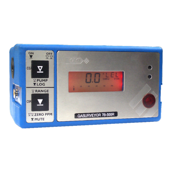
'SAMPLE' This indicates that the pump is running and the instrument is sampling.
'SAMPLE' (Flashing) This indicates that the pump is running at the maximum possible
speed (dependent on battery condition).
'EEEE' or 'EEE' This message is displayed when the 'PPM' or 'Vol Gas' reading exceeds
limits.
'OFF' This indicates that the instrument is about to switch OFF. This command can be
cancelled by a single press of any button.
'SAMPLE FAULT' This indicates a problem with the instrument's flow due to the sample
path being blocked, water ingress, a blocked filter or pump failure. The instrument will alarm
and the pump will switch OFF (not in CSM mode). The sample path should be checked and
'Button 1' pressed to clear sample fault and re-start the pump.
'CHECK ZERO' This indicates that there may have been a zero shift due to the presence of
gas. Switch OFF the instrument and switch ON again in fresh air.
'ZERO FAULT' This indicates that the zero is outwith its calibration limits. Switch the
instrument OFF and then ON again in fresh air. If the fault does not clear, return the
instrument for servicing.
'BAT' This indicates that the battery pack will soon require replacement / recharged. At this
point there will be approximately 30 minutes operation remaining, although this figure will
vary depending on, temperature conditions, usage etc.
'BAT FAULT' This indicates that the battery pack should be replaced / recharged
immediately. As the battery power continues to fall, the pump switches OFF and the LCD
flashes a 'BAT FAULT' message. Subsequently the LCD displays 'OFF' and the instrument
switches off after approximately 5 minutes. The battery pack should be replaced / recharged
immediately.
'1 FAULT' This message can appear after power on, indicating that a calibration data error
has been detected. The instrument should be returned for servicing.
Quick Operating Instructions
Advertisement
Table of Contents

Subscribe to Our Youtube Channel
Summary of Contents for Teledyne GASURVEYOR 7B-500R
- Page 1 ‘ZERO FAULT’ This indicates that the zero is outwith its calibration limits. Switch the instrument OFF and then ON again in fresh air. If the fault does not clear, return the • ‘Gasurveyor 7B-500R’ instruments are certified as: instrument for servicing.
- Page 2 GASURVEYOR 7B-500R - Quick Operating Instructions Button Operation Switch ON (Mode) Change Range: Each single press of ‘Button 2’ changes the range. The display cycles CGI: Press and hold ‘Button 1’ through the available ranges in the following order: (COMBUSTIBLE GAS INDICATOR)


Need help?
Do you have a question about the GASURVEYOR 7B-500R and is the answer not in the manual?
Questions and answers