
Subscribe to Our Youtube Channel
Related Manuals for MICRO-EPSILON capaNCDT 6110 IP


Summary of Contents for MICRO-EPSILON capaNCDT 6110 IP
- Page 1 Operating Instructions capaNCDT 6110/6120/IP CSE05 CSE05/M8 CSF2 CSE1 CSE1,25/M12 CSF4 CSE1,25 CSE2/M16 CSF6 CSE2 CSE3/M24 CSF2-CRg4,0 CSE3 CSF4-CRg4,0 CSF6-CRg4,0...
- Page 2 Non-contact Capacitive Displacement Measuring MICRO-EPSILON MESSTECHNIK GmbH & Co. KG Königbacher Straße 15 94496 Ortenburg / Germany Tel. +49 (0) 8542 / 168-0 Fax +49 (0) 8542 / 168-90 e-mail info@micro-epsilon.de www.micro-epsilon.com...
-
Page 3: Table Of Contents
Contents Safety ............................5 Symbols Used ..............................5 Warnings ................................5 Notes on CE Marking ............................6 Intended Use ..............................7 Proper Environment ............................7 Functional Principle, Technical Data ..................8 Measuring Principle ............................8 Structure ................................9 2.2.1 Sensors ............................11 2.2.2 Sensor Cable.......................... - Page 4 RS485 Interface ........................29 Hardware Interface ............................29 Protocol ................................29 5.2.1 Reading Measuring Values ......................30 5.2.2 Scaling the Measuring Values ..................... 31 5.2.3 Example of the Measuring Value Transmission ................32 5.2.4 Setting the RS485 Address ......................34 Commands and Settings ..........................
-
Page 5: Safety
Safety Safety Knowledge of the operating instructions is a prerequisite for equipment operation. Symbols Used The following symbols are used in this instruction manual: Indicates a hazardous situation which, if not avoided, may result in minor or moder- ate injury. Indicates a situation that may result in property damage if not avoided. -
Page 6: Notes On Ce Marking
Products which carry the CE mark satisfy the requirements of the EU directives cited and the European harmonized standards (EN) listed therein. The EU Declaration of Conformity is available to the responsible authorities according to EU Directive, article 10, at: MICRO-EPSILON Messtechnik GmbH & Co. KG Königbacher Straße 15 94496 Ortenburg / Germany The measuring system is designed for use in industrial environments and meets the requirements. -
Page 7: Intended Use
Safety Intended Use - The capaNCDT 61x0/IP measuring system is designed for use in industrial areas. It is used for ƒ displacement, distance, thickness and movement measurement ƒ position measuring of parts or machine components - The system must only be operated within the limits specified in the technical data, see Chap. 2.3. -
Page 8: Functional Principle, Technical Data
Functional Principle, Technical Data Functional Principle, Technical Data Measuring Principle The principle of capacitive distance measurement with the capaNCDT system is based on the principle of the parallel plate capacitor. For conductive targets, the sensor and the target opposite form the two plate elec- trodes. -
Page 9: Structure
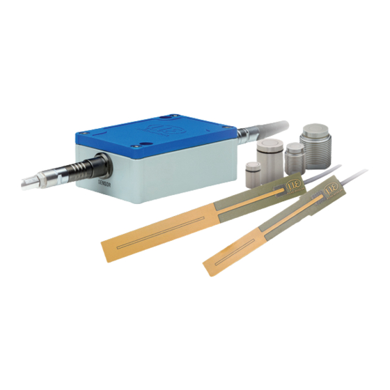
Functional Principle, Technical Data Structure The non-contact, single-channel measuring system of capaNCDT 61xx/IP , installed in an aluminum housing, consists of: - Controller - Sensor - Sensor cable - Power supply and signal cable The signal processing electronics with oscillator, demodulator, AD converter and integrated preamplifier is in the controller Oscillator Voltage... - Page 10 Functional Principle, Technical Data Oscillator Voltage 16 kHz processing 6 pol. connector Sensor Sensor Signal cable Demodulator Preamplifier A/D converter Fig. 3 Block diagram capaNCDT 6120/IP 0xF00000 20 mA 10 V Displacement, mm 4 mA 50 % 100 % Target Sensor Measuring range (MR) Fig.
-
Page 11: Sensors
Functional Principle, Technical Data 2.2.1 Sensors For this measuring system, several sensors can be used. Measuring In order to obtain accurate measuring results, keep the surface of surface sensor the sensor clean and free from damage. The capacitive measuring process is area-related. A minimum area, see Min. -
Page 12: Sensor Cable
Functional Principle, Technical Data 2.2.2 Sensor Cable Sensor and controller are connected by a special, double screened sensor cable. Do not shorten or lengthen these special cables. Usually, a damaged cable can not be repaired. Tread-proof model with metal hose is available for industrial applications. Switch off the device when plugging and removing connectors. -
Page 13: Controller
Functional Principle, Technical Data 2.2.3 Controller The capaNCDT 6110/6120/IP contains a voltage processing, oscillator, integrated preamplifier, demodulator as well as an output level. The voltage processing produces all necessary internal voltages from the power supply. The oscillator sup- plies the sensor with frequency and amplitude-stabilized alternating voltage. The frequency is 16 kHz. The internal preamplifier generates the distance-dependent measuring signal and amplifies it. -
Page 14: Technical Data
Functional Principle, Technical Data Technical Data Controller modell DT6110/IP/U DT6110/IP/I DT6120/IP/U DT6120/IP/I Resolution static 0.01 % FSO (2 Hz) Resolution dynamic 0.02 % FSO (1000 Hz) Frequency response 1 kHz (-3 dB) Linearity ≤ ±0.1 % FSO Sensitivity ≤ ±0.1 % FSO Long-term stability 0.02 % FSO/month Temperature stability... -
Page 15: Delivery
Delivery Delivery Unpacking 1 Controller 1 Power supply and output cable SCAC3/6/IP 1 Instruction Manual Optional accessories: 1 Sensor 1 Sensor cable with connector 1 IF1032/ETH interface converter from analog (DT6110/IP) or RS485 Ethernet (DT6120/IP) on Ethernet/EtherCAT You will find further optional accessories in the appendix. Remove the parts of the system carefully from the packaging and transport them in such a way that they are not damaged. -
Page 16: Installation And Assembly
Installation and Assembly Installation and Assembly Precautionary Measures No sharp-edged or heavy objects should be allowed to affect the sensor cable sheath. Protect the cable against pressure loads in pressurized rooms. Avoid folding the cables in any case. Check the connections for tight fit. A damaged cable cannot be repaired. -
Page 17: Mounting With Thread, Series Csex/Mx Sensors
Mounting with Thread, Series CSEx/Mx Sensors For holders with an internal thread, a mounting nut is suffi- cient for attaching the sensor. For thin holders, Micro-Epsilon recommends mounting nuts on both sides for mounting. Attach the sensor preferably at the end of the thread towards the active measuring surface. -
Page 18: Dimensional Drawings Sensors
Installation and Assembly 4.2.3 Dimensional Drawings Sensors Cylindric sensors CSE05 CSE1 CSE1,25 CSE2 CSE3 ø5.7 ø7.7 ø9.7 ø13.7 ø19.2 (.22 dia.) (.30 dia.) (.38 dia.) (.54 dia.) (.76 dia.) ø6f7 ø8f7 (.24 dia.) (.31 dia.) ø10h7 ø14.0h7 ø20.0h7 (.39 dia.) (.55 dia.) (.79 dia.) Active measuring surface sensor,... - Page 19 Installation and Assembly CSE05/M8 CSE1,25/M12 CSE2/M16 CSE3/M24 WS14 WS18 ø10.4 ø14.4 ø20.6 (.41 dia.) (.57 dia.) (.81 dia.) ø6.0 ø10 ø14.0 ø20.0 (.24 dia.) ø5.7 ø9.7 ø13.7 ø19.2 M8x0.5 M12x1 M16x1 M24x1.5 Fig. 10 Cylindrical sensors with thread and male connector, dimensions in mm (inches) Preferred mounting: Connector side...
- Page 20 Installation and Assembly CSF2 (.55) CSF4 17.5 (.69) CSF6 (.98) (.51) 16.5 (.65) 24.2 (.95) 1.5 (.06) 1.5 (.06) 1.5 (.06) (.03) 4 (.16) (.55) (.55) Fig. 11 Flat sensors with connector Active measuring surface sensor, connector side, dimensions in mm (inches) capaNCDT 61xx/IP Seite 20...
- Page 21 Installation and Assembly CSF2-CRg4,0 (.55) CSF4-CRg4,0 17.5 (.69) CSF6-CRg4,0 (.98) (.51) 16.5 (.65) 24.2 (.95) 1.5 (.06) 1.5 (.06) 1.5 (.06) (0.03) 17.5 ±0.1 (.69) (.20) ø3.1 ±0.1 ±0.1 (.12 dia.) ±0.1 17.5 ø9.4 (.69) (.37 dia.) Active measuring surface sensor Fig.
-
Page 22: Sensor Cable
Installation and Assembly ensor Cable 4.3.1 General The sensor is connected to the controller by the sensor cable. The connection is made by simple plugging. The connector locks automatically with type C and B connectors. The tight fit can be checked by pulling the connector housing (cable bushing). - Page 23 Installation and Assembly 17.5 (.69) 21 (.83) 13.7 (.54) 36.5 +1.0 (1.44) 10.0 (.39) Ø6 (.24) Ø5.4 (.21) Cable length x Fig. 14 Dimensional drawings sensor cable CCgxC CCgxC/90 Dimensions in mm (inches) capaNCDT 61xx/IP Seite 23...
-
Page 24: Cable With Type B Connector
Installation and Assembly 4.3.3 Cable with Type B Connector Sensor cable suitable Type Model Cable length Bending radius for sensors Tread-proof, with protec- static >20 mm CCgx,xB/PT tive metal tubing dynamic >30 mm CSE1,25/M12, CSE2, CSE2/M16, 1 m, 2 m, 4 m, 6 m, 8m static >10 mm CCgx,xB CSE3, CSE3/M24... - Page 25 Installation and Assembly Cable length x 40.4 (1.59) (.39) 35.3 (1.39) (2.24) ø7 (.28 dia.) ø10 (.39) Fig. 16 Dimensional drawing sensor cable CCgxB/90/PT (.94) +1.0 36.5 (1.44) +1.0 10.0 (.39) Ø10 (.39) Ø7 (.28) Cable length x Fig. 17 Dimensional drawings sensor cable CCgxB CCgxB/90 capaNCDT 61xx/IP Seite 25...
-
Page 26: Cable With Type E Connector
Installation and Assembly 4.3.4 Cable with Type E Connector Sensor cable suitable Type Model Cable length Bending radius for sensors With patented min- static >10 mm CSF2, CCgx,xE iature plug for flat dynamic >22 mm CSF4, sensors (recommended 30 mm) CSF6 36.5 (1.44) -
Page 27: Controller
Installation and Assembly Controller 42 (1.65) Mounting holes for M4 screws 53 (2.09) Fig. 19 Dimensional drawing controller Dimensions in mm (inches) capaNCDT 61xx/IP Seite 27... -
Page 28: Ground Connection, Grounding
Installation and Assembly Ground Connection, Grounding Make sure you have a sufficient grounding of the measuring object, for example connect it with the sensor or the supply ground. Power Supply, Display/Output Device, Sensor Connection Color SCAC3/6/IP Signal Description white +24 V +24 V power supply grey Supply ground... -
Page 29: Rs485 Interface
The RS485 interface is only present with the DT6120/IP . You can read the measuring values in digital form via the RS485 interface. MICRO-EPSILON supports you with the driver MEDAQLib, which contains all commands for the capaNCDT 6120/IP . You can download the driver directly under the link http://www.micro-epsilon.de/link/soft-... -
Page 30: Reading Measuring Values
RS485 Interface 5.2.1 Reading Measuring Values Master: Request Data Byte: Value: 0x10 0x4C 0x16 Slave: Response Data Byte: Data[] Value: 0x68 0x68 0x08 0x16 Abbreviations: StartDelimiter (0x10: telegram without data; 0x68 telegram with variable length) Length (number of bytes without SD, LE, LErep, SDrep, FCS, ED) LErep LE repeated SDrep... -
Page 31: Scaling The Measuring Values
The measuring data consists of a counter, the packet length m and the measuring values. The packet length m determines how many measuring values are transmitted. The packet length m is the number of measu- ring values sampled from the electronic, since the last request of measuring data, but is limited to the last 20 measuring values. -
Page 32: Example Of The Measuring Value Transmission
RS485 Interface 5.2.3 Example of the Measuring Value Transmission Master: Request Data Byte: Value: 0x10 0x4C 0x16 DA = Destination address = slave address = 0x7E SA = Source address = master address = 0x01 FCS = Checksum = 0x7E+0x01+0x43 = 0xC2 Slave: Response Data Byte: Data... - Page 33 RS485 Interface Value Name Explanation Data[0] 0x22 Counter [7:0] Measuring value counter = 0x0122 = 290 Data[1] 0x01 Counter [15:8] Data[2] 0x03 Packet length m [7:0] m = 3 -> 3 meas. values Data[3] 0x00 Filler byte [7:0] filler, can be ignored Data[4] 0xB1 Measuring value 1 [7:0]...
-
Page 34: Setting The Rs485 Address
RS485 Interface 5.2.4 Setting the RS485 Address The RS485 address of controller can be changed with this telegram: Master: DSAP SSAP new_addr ID_Hi ID_Lo Lock 0x68 0x09 0x43 0x37 0x3E 0x16 Destination Address (= old Slave address) Source Address = Master Address (e.g. 0x01) Checksum (sum of all bytes without SD, LE, LErep, SDrep, FCS, ED;... -
Page 35: Commands And Settings
RS485 Interface Commands and Settings It can be made even more settings via the RS485 interface: - Filter: ƒ off ƒ moving average (about 2 to 8 values) ƒ arithmetic average (about 2 to 8 values) ƒ Median (about 2 to 8 values) ƒ... -
Page 36: Operation
Operation Operation Connect the display/output devices through the signal output socket, see Chap. 4.6. before connecting the device to the power supply and switching on the power supply. The measuring system is delivered calibrated. Calibration by the user is not necessary. Allow the measuring system to warm up for about 10 minutes before the first measurement. -
Page 37: Maintenance
> Static discharge > Danger of injury If the controller, the sensor or the sensor cable is MICRO-EPSILON MESSTECHNIK defective, please send us the effected parts for GmbH & Co. KG repair or exchange. In the case of faults the cause Königbacher Str. -
Page 38: Liability For Material Defects
Within this period, defective parts, except for wearing parts, will be repaired or replaced free of charge, if the device is returned to MICRO-EPSILON with shipping costs prepaid. Any damage that is caused by improper handling, the use of force or by repairs or modifications by third parties is not covered by the liability for mate- rial defects. -
Page 39: Appendix
Appendix Optional Accessories PS2020 Power supply for DIN rail mounting Input 100 - 240 VAC Output 24 VDC / 2.5 A; L/W/H 120 x 120 x 40 mm Built-in type; mounting on symmetrical DIN-rail 35 mm x 7.5 mm, DIN 50022 PS2401/100-240/24V/1A Wall power supply;... - Page 40 Vacuum feed through Female connector, triax straight, 34 (1.34) Max. leak rate 1x10e-7 mbar · l s-1 2 (0.08) M10x0.75 Compatible with connector type B (M10x0.03) max. 17 (max. 0.67) Vacuum feed through Vacuum feed through triax weldable 25 (.98) Max.
- Page 41 Vacuum feed through Vacuum feed through triax with 25 (.98) CF16 flange UHV/B 13.5 (.53) Max. leak rate 1x10e-9 mbar · l s-1 (.24) Compatible with connector type B Knit line capaNCDT 61xx/IP Page 41...
- Page 42 MICRO-EPSILON MESSTECHNIK GmbH & Co. KG X9751316.01-A011128MSC Königbacher Str. 15 · 94496 Ortenburg / Deutschland MICRO-EPSILON MESSTECHNIK Tel. +49 (0) 8542 / 168-0 · Fax +49 (0) 8542 / 168-90 *X9751316.01-A01* info@micro-epsilon.de · www.micro-epsilon.de...
Need help?
Do you have a question about the capaNCDT 6110 IP and is the answer not in the manual?
Questions and answers