MICRO-EPSILON CS02 Operating Instructions Manual
Hide thumbs
Also See for CS02:
- Operating instructions manual (94 pages) ,
- Instruction manual (68 pages) ,
- Instruction manual (62 pages)
Table of Contents

Related Manuals for MICRO-EPSILON CS02


Summary of Contents for MICRO-EPSILON CS02
- Page 1 Operating Instructions capaNCDT 6200 CS005 CSH1FL CSH2 CSG0.50 CSH05 CS02 CSE2 CSG1.00 CSH05FL CS1HP CSH02 CSE2/M16 CS08 CSH1.2 CSH02FL CSH1.2FL CS05 CSE3/M24 CSE1 CSH2FL CSE05 CSE1,25/M12 CSH3FL CSE05/M8 CS10 CSH1...
- Page 2 Non-contact Capacitive Displacement Measuring MICRO-EPSILON MESSTECHNIK GmbH & Co. KG Koenigbacher Str. 15 94496 Ortenburg / Germany Tel. +49 (0) 8542 / 168-0 Fax +49 (0) 8542 / 168-90 e-mail info@micro-epsilon.com www.micro-epsilon.com...
-
Page 3: Table Of Contents
Contents Safety ............................7 Symbols Used ..............................7 Warnings ................................7 Notes on CE Marking ............................8 Intended Use ..............................9 Proper Environment ............................9 Functional Principle, Technical Data ..................10 Measuring Principle ............................10 Structure ................................ 11 2.2.1 Sensors ............................12 2.2.2 Sensor Cable .......................... - Page 4 Electrical Connections ........................... 40 4.7.1 Connectivity Options ........................40 4.7.2 Pin Assignment Supply, Trigger ....................41 4.7.3 Pin Assignment Analog Output ....................41 4.7.4 Pin Assignment Synchronization ....................42 Operation ..........................44 Starting Up ..............................44 Operating or Display Elements ........................44 5.2.1 LED‘s ............................
- Page 5 6.4.14 Clear Mathematic Function (CMF) ....................68 6.4.15 Ethernet Settings (IPS) ......................... 69 6.4.16 Change between Ethernet and EtherCAT (IFC = Interface) ............69 6.4.17 Query Data Port (GDP) ......................... 70 6.4.18 Set Data Port (SDP) ........................70 6.4.19 Access Channel Information (CHI)....................70 6.4.20 Access Controller Information (COI) ....................
- Page 6 Measurement .......................... 86 Operation and Maintenance ....................87 Liability for Material Defects ....................88 Decommissioning, Disposal ....................88 Appendix ..............................89 Accessories, Service ......................89 A 1.1 Conversion Kit ..............................89 A 1.2 PC6200-3/4 ..............................91 A 1.3 Optional Accessories ............................. 91 A 1.4 Service ................................
-
Page 7: Safety
Safety Safety System operation assumes knowledge of the operating instructions. Symbols Used The following symbols are used in these operating instructions: Indicates a hazardous situation which, if not avoided, may result in minor or moderate injury. Indicates a situation that may result in property damage if not avoided. Indicates a user action. -
Page 8: Notes On Ce Marking
Products which carry the CE mark satisfy the requirements of the EU directives cited and the European harmonized standards (EN) listed therein. The EU Declaration of Conformity is available to the responsible authorities according to EU Directive, article 10, at: MICRO-EPSILON Messtechnik GmbH & Co. KG Koenigbacher Str. 15 94496 Ortenburg / Germany The measuring system is designed for use in industrial environments and meets the requirements. -
Page 9: Intended Use
Safety Intended Use - The capaNCDT 6200 measuring system is designed for use in industrial areas. It is used for ƒ displacement, distance, thickness and movement measurement ƒ position measuring of parts or machine components - The system must only be operated within the limits specified in the technical data, see 2.3. -
Page 10: Functional Principle, Technical Data
Functional Principle, Technical Data Functional Principle, Technical Data Measuring Principle The principle of capacitive distance measurement with the capaNCDT system is based on the principle of the parallel plate capacitor. For conductive targets, the sensor and the target opposite form the two plate elec- trodes. -
Page 11: Structure
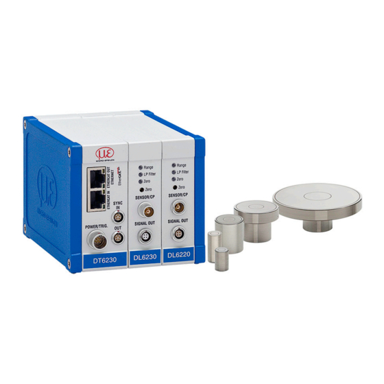
Functional Principle, Technical Data Structure The non-contact, multi-channel measuring system, installed in an aluminum housing, consists of: - A basic module DT 6220 or DT 6230 - A demodulator module DL 6220 or DL 6230, each with integrated preamplifier per sensor - Sensor - Sensor cable - Power supply cable... -
Page 12: Sensors
In the case of insulators the dielectric constant and the target thickness also play an important role. Sensors for electrical conducting targets (metals) Sensor model Measuring range Min. target diameter CS005 0.05 mm 3 mm CS02 0.2 mm 5 mm CSH02 0.2 mm 7 mm CSH02FL 0.2 mm 7 mm CS05 0.5 mm... - Page 13 Functional Principle, Technical Data Sensor model Measuring range Min. target diameter CSH1,2 1.2 mm 11 mm CSH1.FL 1.2 mm 11 mm CSH2FL 2 mm 17 mm 2 mm 17 mm CSH2 2 mm 17 mm CSE2 2 mm 14 mm CSE2/M16 2 mm 14 mm...
-
Page 14: Sensor Cable
Functional Principle, Technical Data 2.2.2 Sensor Cable Sensor and controller are connected by a special, double screened sensor cable. Do not shorten or lengthen these special cables. Usually, a damaged cable can not be repaired. Switch off the device when plugging and removing connectors. Do not crush the sensor cable. -
Page 15: Controller
Functional Principle, Technical Data 2.2.3 Controller The capaNCDT 6200 Multi-channel measuring system consists of a basic module DT62xx and one up to four demodulator modules DL62xx, according to requirements. The components are stored in aluminum hous- ings. Basic module Demodulator module(s) Demodulator module(s) Basic module Fig. - Page 16 Functional Principle, Technical Data Demodulator module DL62xx The demodulator module DL62xx consists of an internal preamplifier, demodulator, output stage and A/D converter. The internal preamplifier generates the distance dependent measuring signal and amplifies it. De- modulator and output stage convert the measuring signal in a standardized voltage and current signal. The measuring values can be processed digitally with the help of the A/D converter.
-
Page 17: Technical Data
Functional Principle, Technical Data Technical Data Controller type DT62x0 with DL6220 DT62x0 with DL6230 Resolution static 0.004 % FSO 0.0005 % FSO Resolution dynamic 0.02 % FSO (5 kHz) 0.005 % FSO (5 kHz) Bandwidth 5 kHz (-3dB) 5 kHz (-3dB) Bandwidth adjustable to 20 Hz to 20 Hz... -
Page 18: Options
Functional Principle, Technical Data Controller type DT62x0 with DL6220 DT62x0 with DL6230 Sensors all sensors suitable all sensors suitable Sensor cable standard CCm1.4x; CCg2.0x CCm1.4x; CCg2.0x ≤ 6 m (with CCgxx) ≤ 4.2 m (with ≤ 6 m (with CCgxx) ≤ 4.2 m (with Sensor cable (matched) CCmxx) CCmxx) - Page 19 Functional Principle, Technical Data Article number Designation Description Suitable for articles 2303019 2303024 2303025 2303030 DL6230 DL6230/ECL2 DL6230/ECL3 DL6230/LC LC DL62x0 Special calibration of linearity on digital ○ ○ ○ 2982044 • digital output LC DL62x0 Special calibration of linearity on analog ○...
-
Page 20: Delivery
Delivery Delivery Unpacking, Included in Delivery 1 Basic module DT62x0 with 1 - 4 demodulator modules DL62x0 1 Power supply and trigger cable PC6200-3/4, 3 m long, see A 1.3 1 Ethernet cable, 3 m long 1 Conversion kit (Springs for mounting on DIN-rail, mounting plates for wall fastening, threaded rods in differ- lengths), see A 1.1. -
Page 21: Installation And Assembly
Installation and Assembly Installation and Assembly Precautionary Measures No sharp-edged or heavy objects may get into contact with the sensor cable sheath. Protect the cable against pressure loads in pressurised rooms. Avoid kinks in any case. Check the connections for tight fit. A damaged cable cannot be repaired. -
Page 22: Circumferential Clamping, Cylindric Sensors
Installation and Assembly 4.2.2 Circumferential Clamping, Cylindric Sensors This sensor mounting option offers maximum reliability because the sensor is clamped around its cylindrical housing. It is absolutely necessary in difficult installation environments, for example on machines, production plants et cetera. Mounting with clamping ring Fig. -
Page 23: Dimensional Drawings Sensors
Installation and Assembly 4.2.4 Dimensional Drawings Sensors Cylindric sensors CS005 CS02 CS05 CSE05 CS08 ø3 (0.118 dia.) ø5.7 (.22) ø6f7 ø10h7 ø6f7 (.236 dia.) ø8f7 (.314 dia.) (.24 dia.) ø6f7(.236 dia.) (.394 dia.) CS1HP CSE2 CSE1 Connector side ø14h7 (0.55 dia.) M=1:2 ø13.7 (0.54 dia.) - Page 24 Installation and Assembly CS10 M=1:2 M=1:2 M=1:2 Connector side ø60h7 (2.36 dia.) ø30h7 (1.18 dia.) ø40h7 (1.58 dia.) Dimensions in mm (inches) Circumferential clamp- ing possible from 3 mm behind the front face. ø20h7 (.79 dia.) ø20h7 (.79 dia.) ø20h7 (.79 dia.) Dimensional drawings of other sensors are available on request.
- Page 25 Installation and Assembly CSH02-CAmx, CSH1-CAmx, appr. 9.4 (.37) appr. 9.4 (.37) CSH05-CAmx CSH1.2-CAmx ø12g6 (.473 dia.) ø8g6 (.315 dia.) ø7.5 ø11.5 (.30 dia.) (.45 dia.) ø2.2 (.09 dia.) ø2.2 (.09 dia.) Dimensions in mm (inches), not to scale capaNCDT 6200 Page 25...
- Page 26 Installation and Assembly CSH2-CAmx appr. 9.4 (.37) ø20g6 (.79) ø19.5 (.77) ø2.2 (.09) Dimensions in mm (inches), not to scale capaNCDT 6200 Page 26...
- Page 27 Installation and Assembly Cylindrical sensors with thread CSE05/M8 CSE1,25/M12 ø10.4 (.41 dia.) ø6.0 ø10 (.24 dia.) Connector side ø5.7 ø9.7 Dimensions in mm (inches) Active measuring surface sensor Dimensional drawings M8x0.5 of other sensors are M12x1 available on request. capaNCDT 6200 Page 27...
- Page 28 Installation and Assembly CSE2/M16 CSE3/M24 WS14 WS18 ø14.4 ø20.6 (.57 dia.) (.81 dia.) ø14.0 ø20.0 ø13.7 ø19.2 Connector side Dimensions in mm (inches) Active measuring surface sensor Dimensional drawings M16x1 of other sensors are available on request. M24x1.5 Preferred mounting: Sensor Torque Screw the sensor into the sen-...
- Page 29 Installation and Assembly Flat sensors appr. 9.4 appr. 9.4 CSH02FL-CRmx, CSH1FL-CRmx, 4 (.16) CSH05FL-CRmx CSH1.2FL-CRmx (.37) (.37) 4 (.16) (.003) (.24) 0.1 (.003) (.22) ø3 ø3 (.29) (.12 dia.) (.12 dia.) ø2.2 ø2.2 (.09) (.09) Dimensions in mm (inches), not to scale capaNCDT 6200 Page 29...
- Page 30 Installation and Assembly CSH2FL-CRmx CSH3FL-CRmx (.20) (.79) (.98) appr. 9.4 15.5 (.06) (.61) (.79) (.09) (.37) appr. 9.4 (.37) (.003) (.003) ø3 (.12) ø3 (.12) ø2.2 (.09) ø2.2 (.09) Cable length 1.4 m visible (incl. crimp sleeve) Dimensions in mm (inches), not to scale capaNCDT 6200 Page 30...
-
Page 31: Sensor Cable
Installation and Assembly CSG0.50-CAm2.0 and CSG1.00-CAm2.0 Thickness 0.9 -0.05 (0.04 -0.002 Sensor structures 9.9 (0.39) 1 (0.04) 200 (7.87) 216 (8.5) Sensor structures 4.2 (0.17) (0.11) 3.85 (0.15) (0.18) CSG0,50-CAm2,0 CSG1,00-CAm2,0 Dimensions in mm (inches), not to scale ensor Cable The sensor is connected to the controller by the sensor cable. - Page 32 Installation and Assembly Sensor cable CCgxC/90 Sensor cable CCgxC 21 (.83) 26.5 ø6 (.24) (.34) (1.04) 36.5 13.7 (.54) (1.44) ø5.4 (.21) 17.5 (.69) Cable length x Sensor cable CCgxB/90 Sensor cable CCgxB 25 (.98) 26.5 (1.04) ø10 (.39) 36.5 (1.44) Cable length x ø7(.28)
- Page 33 Installation and Assembly Sensor cable CCmxC/90 21 (.83) Sensor cable CCmxC ø6 (.24) 8.6 (.34) 27 (1.06) ø5.4 (21) 37 (1.46) 13.7 (.54) 17.5 (.69) Cable length x Sensor cable CCmxB/90 Sensor cable CCmxB 25 (.98) 27 (1.06) ø10 37 (1.46) (.39) Cable length x Dimensions in mm (inches), not to scale...
-
Page 34: Controller
Installation and Assembly Controller 4.4.1 Basic Unit, Demodulator Module 25 (.98) 34 (1.34) 125 (4.92) DT 6220 DL 6220 Fig. 7 Dimensional drawing controller Dimensions in mm (inches), not to scale capaNCDT 6200 Page 34... -
Page 35: Housing Cover
Installation and Assembly 4.4.2 Housing Cover Mounting hole M4 for wall fastening respectively mounting on DIN-rail 8 (.31) 90 (3.54) (.20) (.31) Fig. 8 Dimensional drawing housing cover Dimensions in mm (inches), not to scale The controller is mounted using mounting plates or holding clamps for a mounting on DIN-rail which are included with the conversion kit supplied, see A 1.1. -
Page 36: Insert Demodulator Module
Installation and Assembly Insert Demodulator Module Unscrew the sleeve nuts (4b) on the right side of the controller, remove the right housing cover (3). Remove a sleeve nut (4a) with threaded rod (1). Successively replace the threaded rod (1) by a threaded rod next longer from the supplied conversion kit. - Page 37 Installation and Assembly Connect both flat flexible cables (5) of the preceding demodulator module with the new demodulator module (6). Wiring preceding demodulator module Wiring following demodulator module Fig. 10 Wiring demodulator modules Put on the right housing cover (3). Screw the sleeve nuts (4b) on the threaded rods on the right side of the controller and tighten the sleeve nuts.
- Page 38 Installation and Assembly Fig. 11 Use of the plugging off assistance for the wiring of the demodulator elements capaNCDT 6200 Page 38...
-
Page 39: Ground Connection, Earthing
Different to other systems, with capaNCDT systems is no target earthing necessary The drawing below shows two synchronized capaNCDT sensors, measuring against a mill, see Fig. 12. Due to the unique synchronizing technique of MICRO-EPSILON a special target earthing is not needed in most cases. Sensor Controller sync. -
Page 40: Electrical Connections
Installation and Assembly Electrical Connections 4.7.1 Connectivity Options The power supply and the signal output are located at the front side of the controller. Controller EtherCAT (optional) E th LAN cable RJ-45-connectors CCxxx PS 2020 Ethernet Sensor Ammeter/Voltmeter Fig. 14 Measuring system assembly capaNCDT 6200 Page 40... -
Page 41: Pin Assignment Supply, Trigger
Installation and Assembly 4.7.2 Pin Assignment Supply, Trigger Color Signal Description PC6200-3/4 ETHERNET brown +24VIN +24 VDC Supply white Zero VIN GND Supply yellow TRI_IN+ Trigger IN+, TTL level POWER/TRIG. green TRI_IN- Trigger IN- DT62xx shield PC6000-3/4 is a 3 m (13.12 ft) long, pre-assembled power View on solder pin side, Power supply input supply and trigger cable. -
Page 42: Pin Assignment Synchronization
Installation and Assembly 4.7.4 Pin Assignment Synchronization Assignment Insulation Color Twisted Pair 1 1 white 1 SYNC Twisted Pair 1 blue blue POWER/TRIG. Twisted Pair 2 2 white 2 Twisted Pair 2 orange orange SC6000-x is a 0,3 or 1 m long, preassembled synchronization View on solder pin Sync IN/OUT on cable... - Page 43 Installation and Assembly Controller 2 SC6000-x Controller 1 Fig. 15 Synchronization of a second controller capaNCDT 6200 Page 43...
-
Page 44: Operation
Operation Operation Starting Up Connect the the display/output devices through the signal output socket, see 4.7, see 4.7.2, see 4.7.3, before connecting the device to the power supply and switching on the power supply. Allow the measuring system to warm up before the first measurement or calibration for approximately 15 min. -
Page 45: Poti
Operation 5.2.2 Poti The zero-poti on the demodulator modules is used for zero adjustment of the analog outputs. End positions on the left or right stop are marked by a slight click. The electrical zero point can be set across the whole measuring range with the “zero” potentiometer. The start of the measuring range (= mechanical zero point) is on the front face of the sensor. -
Page 46: Change Ethernet / Ethercat
Operation 5.2.3 Change Ethernet / EtherCAT Fig. 17 Change Ethernet/EtherCAT A switch between Ethernet and EtherCAT, is possible via a hardware switch, see Fig. 17 or via software on the basic unit DT6230, see 7.2. If the switch is in position EN (Ethernet), always the Ethernet interface is active independent of the software setting. -
Page 47: Triggering
Operation Triggering The measuring value output on capaNCDT 6200 is controllable by an external electrical trigger signal or com- mand. Here, only the digital output is affected. Triggering release by: Controller Trigger in I = 5 ... 45 mA - Trigger input (pin 3 and pin 4 on 4-pole power supply 100 Ohm connector, see 4.7.2 U trigger... - Page 48 Operation Edge triggering. Starts measuring value output, as soon as the rising edge on the trigger input is active. If trigger conditions are met, the controller outputs a measuring value. The set data rate must be greater than the maximum trigger frequency. If triggering is faster than the set data rate, individual measuring values are transmitted twice, because internally no new mea- suring values of the AD converter are active.
-
Page 49: Measurement Averaging
Operation Measurement Averaging 5.5.1 Introduction Measurement averaging is performed before the output of measuring values via the Ethernet interfaces. Measurement averaging improves the resolution, allows masking individual interference points or “smoothes” the reading. Linearity is not affected by averaging. Averaging has no effect on measuring frequency and output rate. The controller is delivered ex factory without measurement averaging. -
Page 50: Arithmetic Average Value
Operation 5.5.3 Arithmetic Average Value The arithmetic average value M is set and output over the selected number N of successive measuring val- ues. Method Measuring values are collected and the average value is calculated consequently. This method leads to a reduction of the amount of data, because an average value is output only after every Nth measuring value. -
Page 51: Ethernet Interface
You will achieve especially high resolutions if you readout the measurements in digital form via the Ethernet interface. For that purpose, use the web interface or a special program. MICRO-EPSILON supports you by the driver MEDAQLib, containing all commands for capaNCDT 6200. - Page 52 Ethernet Interface Define the following address in the properties of the LAN connection: IP address: 169.254.168.1 Subnet mask: 255.255.0.0 Select Properties. Select Internet Protocol (TCP/IP) > Properties. capaNCDT 6200 Page 52...
- Page 53 Ethernet Interface By default, the IP address of the controller is set to 169.254.168.150. Communication with the controller is done on the data port 10001 for measurement transmission. A command port (Telnet, port 23) is used for sensor commands. The IP settings and the data port can be changed at any time: - by using the web browser.
- Page 54 Ethernet Interface If you activate DHCP , access to the controller via a DHCP host name is possible. The host name contains the device name and serial number. Structure: NAME_SN e. g. DT6220_1001. The controller supports UPnP . If you use an operational system with activated UPnP client e. g. standard with Windows 7, the controller is listed in the explorer as a device automatically.
-
Page 55: Data Format Of Measuring Values
Ethernet Interface Data Format of Measuring Values All measuring values, recorded at a time, are combined into a measuring value frame (One measuring value per channel). Several measuring value frames are combined to a measuring value block and then transmitted together with a header as a TCP packet. -
Page 56: Settings
Ethernet Interface All measuring values are transmitted as Int32. The measuring value resolution is 24 bits i.e only the most low- order 24 bits of integer number are used. Hexadecimal range: 0 ... FFFFFF . Exception is the mathematics function, because the result can also be greater than 24 bits. Scaling of measuring values: Digital value (Int) Measurement in µm =... - Page 57 Ethernet Interface Linearization Options: - Offset correction - 2-point-linearization - 3-point-linearization - 5-point-linearization - 10-point-linearization Up to 10 linearization points can be measured for each channel. These are at 10 %, 20 %, 30 %, 40 %, 50 %, 60 %, 70 %, 80 %, 90 % and 100 % of the measurement range. That means, for example, that the sensor is adjusted to 10 % of the measurement range.
- Page 58 Ethernet Interface Ideal characteristic Actual characteristic 5-Point calibration 50 % 100 % Measurement range Fig. 24 Output characteristic for the measurement The software linearization affects only the values (averaging also), which are output via the Ethernet interface. Mathematic functions: For Calculation of several channels. capaNCDT 6200 Page 58...
-
Page 59: Commands
Ethernet Interface Commands All commands are transmitted via port 23 (Telnet). Each command starts with a $ character. The controller ignores all characters, which are transmitted before the $ character. The controller immediately returns all transmitted characters back as echo. After the response has been sent, the controller starts to send measurement values gain (applies to the oper- ating mode ”continuous transmission”). - Page 60 Ethernet Interface Possible sample times n (in µs) corresponds to data rate 384000 2.6 Sa/s 192000 5.2 Sa/s 96000 10.4 Sa/s 64000 15.6 Sa/s 38400 26 Sa/s 32000 31.3 Sa/s 19200 52.1 Sa/s 16000 62.5 Sa/s 9600 104.2 Sa/s 1920 520.8 Sa/s 1041.7 Sa/s 2083.3 Sa/s...
-
Page 61: Trigger Mode (Trg)
Ethernet Interface 6.4.2 Trigger Mode (TRG) There are three possible settings regarding the trigger input, see 5.4. Irrespective of the trigger mode set, a single measured value per channel can be called up by means of a software command, see 6.4.3. -
Page 62: Filter, Averaging Type (Avt)
Ethernet Interface 6.4.4 Filter, Averaging Type (AVT) Mode of measurement averaging Command $AVTn<CR> Response $AVTnOK<CRLF> Index n = 0: No averaging (Default setting) n = 1: Moving average n = 2: Arithmetic average (outputs only each nth measuring value) n = 3: Median n = 4: Dynamic noise rejection ? = Request averaging type Request averaging type... -
Page 63: Channel Status (Chs)
Ethernet Interface 6.4.6 Channel Status (CHS) Specifies in increasing order in which channels there is a module. (0 = no channel available, 1 = channel available, 2 = math function is output on this channel) Command $CHS<CR> Response $CHS1,0,2,1OK<CRLF>(Example: Channel 1,3,4 available, channel 3 with math function) 6.4.7 Mode of Linearization (LIN) -
Page 64: Set Linearization Point (Slp)
Ethernet Interface 6.4.8 Set Linearization Point (SLP) Sets a linearization point. Place the sensor or the target in the corresponding position. After the command has been received, the current measuring value will be recorded at this position as a linearization point and thus the constants are recalculated for the linearization. -
Page 65: Get Linearization Point (Glp)
Ethernet Interface 6.4.9 Get Linearization Point (GLP) Reads out the linearization point. The value is output hex format. Command $GLPm:n<CR> (for example: $GLP4:3<CR> = linearization point at 30 % of channel 4) Response $GLPm:n,……OK<CRLF> (for example $GLP5:3,A034C9OK<CRLF>) Index m (channel number): 1…4 n (linearization point): 1 = linearization point at 10 % of measuring range 2 = linearization point at 20 % of measuring range... -
Page 66: Version (Ver)
Ethernet Interface 6.4.11 Version (VER) Requesting the current software version including date. Command $VER<CR> Response $VERDT6200;V1.2a;8010079<CRLF> 6.4.12 Set Mathematic Function (SMF) Sets a math function on a certain channel. Command $SMFm:Offset,Factor1,Factor2,Factor3,Factor4<CR> Response $SMFm:Offset,Factor1,Factor2,Factor3,Factor4,OK<CRLF> Index m: 1…4 If a channel is selected, which is already (Channel number) reserved by electronics, the result of the math function is now transmitted instead of the mea-... - Page 67 Ethernet Interface Example: $SMF2:+1FFFFF,+1.0,+0.0,+0.0,-0.3<CR> On channel 2 the sequent math function is output: 100 % Offset + 1 * channel 1 - 0.3 * channel 4 Sensor 1 Sensor 2 MR1 mm MR 1 mm 2 mm Fig. 25 Example for thickness measurement of a target with two capacitive sensors Following math function is required for the above adjustment for thickness measurement of the target.
-
Page 68: Get Mathematic Function (Gmf)
Ethernet Interface 6.4.13 Get Mathematic Function (GMF) Reads out the math function of a channel. Command $GMFm<CR> Response $GMFm:Offset,Factor1,Factor2,Factor3,Factor4OK<CRLF> Index m: 1…4 If a channel is selected, which is already reserved (Channel number) by electronics, the result of the math function is now transmitted instead of the measured value. -
Page 69: Ethernet Settings (Ips)
Ethernet Interface 6.4.15 Ethernet Settings (IPS) Changes the IP settings of the controller. Command $IPSm,<IPAddress>,<SubnetAddress,<GatewayAddress> <CR> Example $IPS0,169.254.168.150,255.255.0.0,169.254.168.1<CR> Response $IPSm,<IPAddress>,<SubnetAddress>,<GatewayAddress>OK<CRLF> Index m = 0: static IP address m = 1: activates DHCP* * If DHCP is active, no IP subnet- and gateway address has to be transmitted. Request settings Command... -
Page 70: Query Data Port (Gdp)
Ethernet Interface 6.4.17 Query Data Port (GDP) Queries the port number of the data port. Command $GDP<CR> $GDP<Port number>OK<CRLF> Response Example: $GDP10001OK<CRLF> 6.4.18 Set Data Port (SDP) Sets the port number of the data port. Range: 1024 ...65535. Command $SDP<Portnumber><CR> Example: $SDP10001OK<CR> Response $SDP<Portnumber>OK<CRLF>... -
Page 71: Access Controller Information (Coi)
Ethernet Interface 6.4.20 Access Controller Information (COI) Reads information of the controller (e.g. serial number). Command $COI<CR> Response $COIANO...,NAM...,SNO...,OPT...,VER...OK<CRLF> Index ANO = Article number NAM = Name SNO = Serial number OPT = Option VER = Firmware version 6.4.21 Login for Web Interface (LGI) Changes the user level for the web interface on professional. -
Page 72: Change Password (Pwd)
Ethernet Interface 6.4.23 Change Password (PWD) Changes the password of the device (required for the web interface and the sensorTOOL). Command $PWD<oldpassword>,<newpassword>,<newpassword><CR> $PWD<oldpassword>,<newpassword>,<newpassword>OK< CRLF> Response A password can be from 0-16 characters and must contain only letters and numbers. When delivered, no password is assigned. The field can remain empty/blank. -
Page 73: Set Analog Filter (Alp)
Ethernet Interface 6.4.26 Set Analog Filter (ALP) Enables/Disables a low pass filter with 20 Hz limit frequency on analog output Command $ALPn<CR> Response $ALPnOK<CRLF> 0 = Low pass filter not active Index 1 = Low pass filter is active Request $ALP? Response $ALP?nOK<CRLF>... -
Page 74: Operation Using Ethernet
Ethernet Interface Operation Using Ethernet Dynamic web pages are generated in the controller which contain the current settings of the controller and the peripherals. Operation is only possible while there is an Ethernet connection to the controller. 6.5.1 Requirements You need a web browser with HTML5 support (e.g. Mozilla Firefox 3.5 or Internet Explorer 10) on a PC with a network connection. - Page 75 PC uses, for example, the fol- “DT6230_01234567”. lowing IP address: 169.254.168.1. Interactive web pages for setting the controller and peripherals are now shown in the web browser. The sensorTOOL program is available online at https://www.micro-epsilon.com/download/software/sensorTool.exe. capaNCDT 6200 Page 75...
-
Page 76: Access Via Web Interface
Ethernet Interface 6.5.2 Access via Web Interface 2279 Fig. 26 First interactive web page after calling the IP address Use the upper navigation bar to access additional features (e. g. Settings etc.). All settings on the web page are applied immediately in the controller. Parallel operation with web interface and Telnet commands is possible;... -
Page 77: Channel N
Ethernet Interface Channel n 6.6.1 Channel Information, Measuring Range Menu Settings > Channel n > Channel information. The measuring ranges of the connected sensors must be entered manually. Do not forget to enter the new range after changing a sensor. Data channel 1 / 2 / 3 / 4 Value... - Page 78 Ethernet Interface 10 % Measuring range Measuring range 90 % Sensor Sensor Click on the Reset button in web interface in the line 90 % Click on the Reset button in web interface in the line 10 % The program will calculate the correction curve from the three Adjust the target to 50 % of the measuring range to the data points.
-
Page 79: Math Function
Ethernet Interface 6.6.3 Math Function This function enables the scaling of a measuring channel and the mathematical combination of individual channels. Formula: Data channel = Offset + factor measurement channel 1 + factor measurement channel 2 + factor measurement channel 3 + factor measure- ment channel 4. -
Page 80: Measurement Settings
Ethernet Interface Measurement Settings 6.7.1 Measurement Mode Menu Settings > Measurement settings > Measurement mode data rate: 3906.25 Hz, filter type: Off, High speed analog low pass: inactive data rate: 1041.67 Hz, filter type: Median, Balanced filter width: 3, analog low pass: inactive data rate: 104.17 Hz, filter type: Median, Low noise filter width: 7, analog low pass: active... -
Page 81: Filter Type / Averaging
Ethernet Interface 6.7.1.2 Filter type / Averaging No Averaging Designation of averaging type. Av- Moving average Value eraging number indicates, about Filter width 2 / 3 / how many current measuring Filter type Arithmetic mean Value values should be averaged in the 4 / 5 / 6 / 7 / 8 controller, before a new measur- Median... -
Page 82: System Settings
Ethernet Interface System Settings 6.8.1 Language Selection The web interface promotes the units millimeter (mm) when displaying measuring results. You can choose German, English, Chinese, Japanese, Korean or the preset browser language in the web interface. You can also change the language in the menu bar. 6.8.2 Login, Changing User Level Menu Settings >... -
Page 83: Password
Ethernet Interface 6.8.3 Password Assigning passwords prevents unauthorized changes to controller settings. In the delivery state, no password is deposited in the controller. A firmware update will not change the custom password. After the controller has been configured, you should enable password protection. Change to the menu Settings >... -
Page 84: Import, Export
Ethernet Interface 6.8.5 Import, Export Menu Settings > System settings > Manage settings Here you can export all controller settings in a file or reimport them from a file. The Export feature generates a text file which you can either store or display with an editor. -
Page 85: Ethercat Interface
EtherCAT Interface EtherCAT Interface Introduction The EtherCAT interface allows a fast transfer of measured values . The controller supports CANopen over EtherCAT (CoE). Service Data Objects SDO: All parameters of the controller can thus be read or modified. Process Data Objects PDO: A PDO telegram is used for real-time transmission of measured values. Individual objects are not addressed. -
Page 86: Measurement
Measurement A change from the EtherCAT interface back to the Ethernet interface is possible with the hardware switch on the DT6230 basic unit or via the corresponding CoE Object. In both cases, then a restart of the controller is required. To integrate the EtherCAT interface e.g. -
Page 87: Operation And Maintenance
> Static discharge > Danger of injury If the controller, the sensor or the sensor cable is MICRO-EPSILON MESSTECHNIK defective, please send us the affected parts for GmbH & Co. KG repair or exchange. If the cause of a fault cannot Koenigbacher Str. -
Page 88: Liability For Material Defects
The warranty period lasts 12 months following the day of shipment. Defective parts, except wear parts, will be repaired or replaced free of charge within this period if you return the device free of cost to MICRO-EPSILON. This warranty does not apply to damage resulting from abuse of the equipment and devices, from forceful handling or installation of the devices or from repair or modifications performed by third parties. -
Page 89: Appendix
Appendix| Accessories, Service Appendix Accessories, Service A 1.1 Conversion Kit The conversion kit is contained in the scope of supply, see 3.1. Ground terminal ø 4,3 mm (.17.3 dia.) Ground connection Mounting clamps for mounting 20 x 0.8 mm/ CK75G hardened/ on DIN-rail plated Mounting clamps for... - Page 90 Appendix| Accessories, Service Mounting plate Aluminum / powder-coated Plugging off assistance for con- nector (.12) (.39) (.03) (.79) Dimensions in mm (inches), not to scale Further more, the conversion kit contains sleeve nuts, threaded rods in different lengths and screws. capaNCDT 6200 Page 90...
-
Page 91: Pc6200-3/4
Appendix| Accessories, Service A 1.2 PC6200-3/4 The PC6200-3/4 is contained in the scope of supply, see 3.1. PC6200-3/4 Power supply and trigger cable, 3 m long A 1.3 Optional Accessories MC2.5 Micrometer calibration fixture, setting range 0 - 2.5 mm, reading 0.1 µm, for sensors CS005 to CS2 MC25D Digital micrometer calibration fixture,... - Page 92 Appendix| Accessories, Service SWH.OS.650.CTMSV Vacuum feed through, 34 (1.34) Max. leak rate 1x10e- mbar · l s M10x0.75 Compatible with connector type B (.08) max. 17 (.67) capaNCDT 6200 Page 92...
- Page 93 Appendix| Accessories, Service UHV/B Vacuum feed through triax weldable Max. leak rate 1x10e- mbar · l s 25 (.98) Compatible with connector type B ø13.50h6 SW11 Vacuum feed through triax with CF16 25 (.98) flange 13.5 (.53) Max. leak rate 1x10e-9 mbar · l s Compatible with connector type B (.24) Knit line...
-
Page 94: A 1.4 Service
Appendix| Accessories, Service SCACx/4 Signal output cable analog, x m long (necessarily for multi-channel operation) SC6000-x Synchronization cable PS2020 Power supply for mounting on DIN-rail input 230 VAC (115 VAC) output 24 VDC / 2.5 A; L/W/H 120 x 120 x 40 mm A 1.4 Service Function and linearity check-out, inclusive 11-point protocol with grafic and post-calibration. -
Page 95: Factory Setting
Appendix| Factory Setting Factory Setting Analog: Digital: - Zero-poti = Off (right-stop) - Data rate = 3906 Sa/s - LP filter 20 Hz = Off - Filter = Off - Linearization = Off - Trigger mode = Off - Math functions = Off - IP address = Static IP... -
Page 96: Tilt Angle Influence On The Capacitive Sensor
CS10 CS02 Figures give an influence example shown on the sensors CS02/CS1 and CS10 in the case of different sensor distances to the target. As this results from internal simulations and cal- culations, please request for detailed informa- tion. -
Page 97: Measurement On Narrow Targets
Appendix| Measurement on Narrow Targets Measurement on Narrow Targets 50 % 50 % 45 % 45 % 40 % 40 % 35 % 35 % 30 % 30 % 25 % 25 % 3 mm 20 % 20 % 3 mm 4 mm 15 % 15 %... -
Page 98: Measurements On Balls And Shafts
Figures give an influence example shown on the sensors CS02 and CS1 in the case of different sensor distances to the target as well as target diameters. As this results from internal simulations and calcula- tions, please request for detailed information. -
Page 99: Ethercat Documentation
Appendix| EtherCAT Documentation EtherCAT Documentation EtherCAT® is, from the Ethernet viewpoint, a single, large Ethernet station that transmits and receives Ether- net telegrams. Such an EtherCAT system consists of an EtherCAT master and up to 65535 EtherCAT slaves. Master and slaves communicate via a standard Ethernet wiring. On-the-fly processing hardware is used in each slave. -
Page 100: A 6.1.2 Ethercat® Services
Appendix| EtherCAT Documentation A 6.1.2 EtherCAT® Services In EtherCAT® services for the reading and writing of data are specified in the physical memory of the slave hardware. The following EtherCAT® services are supported by the slave hardware: - APRD (Autoincrement physical read, Reading of a physical area with auto-increment addressing) - APWR (Autoincrement physical write, Writing of a physical area with auto-increment addressing) - APRW (Autoincrement physical read write, Reading and writing of a physical area with auto-increment ad- dressing) -
Page 101: A 6.1.3 Addressing And Fmmus
Appendix| EtherCAT Documentation A 6.1.3 Addressing and FMMUs In order to address a slave in the EtherCAT® system, various methods from the master can be used. The DT6230 supports as full slave: - Position addressing The slave device is addressed via its physical position in the EtherCAT® segment. The services used for this are APRD, APWR, APRW. -
Page 102: A 6.1.5 Ethercat State Machine
Appendix| EtherCAT Documentation A 6.1.5 EtherCAT State Machine The EtherCAT® state machine is implemented in each EtherCAT®. Directly after switching on the capaNCDT 6500, the state machine is in the “Initialization“ state. In this state, the master has access to the DLL informa- tion register of the slave hardware. -
Page 103: A 6.1.6 Canopen Over Ethercat
Appendix| EtherCAT Documentation A 6.1.6 CANopen over EtherCAT The application level communication protocol in EtherCAT is based on the communication profile CANopen DS 301 and is designated either as “CANopen over EtherCAT” or CoE. The protocol specifies the object directory in the sensor, as well as the communication objects for the exchange of process data and acyclic messages. -
Page 104: A 6.1.8 Service Data Sdo Service
Appendix| EtherCAT Documentation A 6.1.8 Service Data SDO Service Service Data Objects (SDOs) are primarily used for the transmission of data that are not time critical, e.g. pa- rameter values. EtherCAT specifies the SDO services as well as the SDO information services: SDO services make possible the read/write access to entries in the CoE object directory of the device. - Page 105 Appendix| EtherCAT Documentation Object 1000h: Device type 1000 Device type 0x00200000 Unsigned32 Provides information about the used device profile and the device type. Object 1001h: Error register 1001 Error register 0x00 Unsigned8 Object 1008h: Manufacturer device name 1008 Device name DT6230 Visible String Object 1009h: Hardware version...
- Page 106 Appendix| EtherCAT Documentation Object 1A00h: TxPDO Mapping 1A00 RECORD TxPDO Mapping Subindices Number of entries Unsigned8 Subindex 001 0x0000:00 Unsigned32 Subindex 002 0x6020:03 Unsigned32 Subindex 003 0x6020:08 Unsigned32 Subindex 004 0x6020:09 Unsigned32 Subindex 005 0x6020:0A Unsigned32 Subindex 006 0x6020:0B Unsigned32 Object 1C13h: TxPDO assign 1C13 RECORD...
-
Page 107: A 6.2.2 Manufacturer Specific Objects
Appendix| EtherCAT Documentation A 6.2.2 Manufacturer Specific Objects Overview Index (h) Name Description 2010 Controller info Controller information 2020 Channel 1 Info Information and settings of channel 1 2021 Channel 2 Info Information and settings of channel 2 2022 Channel 3 Info Information and settings of channel 3 2023 Channel 4 Info... - Page 108 Appendix| EtherCAT Documentation Object 2020h: Channel information 2020 RECORD Channel 1 info Subindices Number of entries Unsigned8 Name DL6230 Visible String Serial No xxxxxxxx Unsigned32 Status Active Enum Range Unsigned32 Unit µm Enum Linearization Enum The structure of objects 2021h to 2027h corresponds to the object 2020h. Object 2060h: Controller settings 2060 RECORD...
- Page 109 Appendix| EtherCAT Documentation Object 2100h: Controller interface 2100 RECORD Controller Interface Subindices Number of entries Unsigned8 Ethernet/EtherCAT EtherCAT Enum Ethernet Adress type Static Enum Ethernet IPAddress 169.254.168.150 Visible String Ethernet Subnet 255.255.0.0 Visible String Ethernet Gateway 169.254.168.1 Visible String Ethernet Dataport 10001 Unsigned16 Object 2200h: Commands...
-
Page 110: Measurement Data Format
Appendix| EtherCAT Documentation Object 6020h: Measuring values 6020 RECORD Measuring values Subindices Number of entries Unsigned8 Counter xxxx Unsigned32 Channel 1 xxxx Float Channel 2 xxxx Float Channel 3 xxxx Float Channel 4 xxxx Float A 6.3 Measurement Data Format The measuring values are transmitted as Float. -
Page 111: A 6.4 Ethercat Configuration With The Beckhoff Twincat©-Manager
EtherCAT Configuration with the Beckhoff TwinCAT©-Manager For example the Beckhoff TwinCAT Manager can be used as EtherCAT Master. Copy the device description file (EtherCAT®-Slave Information) Micro-Epsilon.xml in the directory \\TwinCAT\IO\EtherCAT (for TwinCATV2.xx) or \\TwinCAT\3.1\Config\IO\EtherCAT (for TwinCAT V3.xx), before the measuring device can be configured via EtherCAT®. - Page 112 Appendix| EtherCAT Documentation The window Scan for boxes (EtherCAT®-Slaves) appears. Confirm with OK. Confirm with Ja. The capaNCDT 6200 is now listed in the Solution explorer. Now confirm the window Activate Free Run with Ja. capaNCDT 6200 Page 112...
- Page 113 Appendix| EtherCAT Documentation The current status should be at least PREOP, SAFEOP or OP on the Online side. Example for a complete object directory (subject to change without prior notice). capaNCDT 6200 Page 113...
- Page 114 Appendix| EtherCAT Documentation On the Process data side the PDO allocations can be read from the device. The selected measuring values are transmitted as process data in the status SAFEOP and OP. capaNCDT 6200 Page 114...
- Page 116 MICRO-EPSILON MESSTECHNIK GmbH & Co. KG Koenigbacher Str. 15 · 94496 Ortenburg / Germany X9751298-B082032HDR Tel. +49 (0) 8542 / 168-0 · Fax +49 (0) 8542 / 168-90 info@micro-epsilon.com · www.micro-epsilon.com MICRO-EPSILON MESSTECHNIK...
Need help?
Do you have a question about the CS02 and is the answer not in the manual?
Questions and answers