Table of Contents

Related Manuals for MICRO-EPSILON capaNCDT 6222


Summary of Contents for MICRO-EPSILON capaNCDT 6222
- Page 1 Operating Instructions capaNCDT 6222 CS005 CSH1FL CSH2 CSG0.50 CSH05 CS02 CSE2 CSG1.00 CSH05FL CS1HP CSH02 CSE2/M16 CS08 CSH1.2 CSH02FL CSH1.2FL CS05 CSE3/M24 CSE1 CSH2FL CSE05 CSE1,25/M12 CSH3FL CSE05/M8 CS10 CSH1...
- Page 2 Non-contact Capacitive Displacement Measuring MICRO-EPSILON MESSTECHNIK GmbH & Co. KG Koenigbacher Str. 15 94496 Ortenburg / Germany Tel. +49 (0) 8542 / 168-0 Fax +49 (0) 8542 / 168-90 e-mail info@micro-epsilon.com www.micro-epsilon.com...
-
Page 3: Table Of Contents
Flat Sensors ..........................21 4.2.4 Dimensional Drawings Sensors ....................22 Sensor Cable ..............................30 Controller ............................... 33 4.4.1 Basic Unit, Demodulator Module ....................33 4.4.2 Housing Cover ..........................34 Insert Demodulator Module ........................... 35 Ground Connection, Earthing ........................38 capaNCDT 6222... - Page 4 Get Linearization Point (GLP) ....................... 62 6.4.10 Status (STS)..........................62 6.4.11 Version (VER) ..........................63 6.4.12 Set Mathematic Function (SMF) ....................63 6.4.13 Get Mathematic Function (GMF) ....................65 6.4.14 Clear Mathematic Function (CMF) ....................65 6.4.15 Ethernet Settings (IPS) ......................... 66 capaNCDT 6222...
- Page 5 Trigger Mode ..........................77 System Settings ............................. 78 6.8.1 Language Selection........................78 6.8.2 Login, Change of the User Level ....................78 6.8.3 Password ............................79 6.8.4 Ethernet Settings .......................... 79 6.8.5 Import, Export ..........................80 Firmware Update ............................81 capaNCDT 6222...
- Page 6 PC6200-3/4 ..............................86 A 1.4 Optional Accessories ............................. 86 A 1.5 Service ................................89 Factory Setting ........................90 Tilt Angle Influence on the Capacitive Sensor ..............91 Measurement on Narrow Targets ..................92 Measurements on Balls and Shafts ..................93 capaNCDT 6222...
-
Page 7: Safety
Avoid shocks and impacts to the sensor and controller. > Damage to or destruction of the sensor and/or controller The supply voltage must not exceed the specified limits. > Damage to or destruction of the sensor and/or controller capaNCDT 6222 Page 7... -
Page 8: Notes On Ce Marking
> Destruction of the sensor > Failure of the measuring device Notes on CE Marking The following apply to the capaNCDT 6222: - EU directive 2004/108/EU - EU directive 2011/65/EU, “RoHS“ Category 9 Products which carry the CE mark satisfy the requirements of the EU directives cited and the European harmonized standards (EN) listed therein. -
Page 9: Intended Use
Safety Intended Use - The capaNCDT 6222 measuring system is designed for use in industrial areas. It is used for ƒ displacement, distance, thickness and movement measurement ƒ position measuring of parts or machine components - The system must only be operated within the limits specified in the technical data, see Chap. 2.3. -
Page 10: Functional Principle, Technical Data
Measuring electrode (metals) without any additional electronic linearization. Slight changes in the conductivity or magnetic proper- ties do not affect the sensitivity or linearity. Electrical conductor Fig. 1 Functional principle of the guard ring capacitor capaNCDT 6222 Page 10... -
Page 11: Structure
Analog filter Preamplifier Preamplifier digital adjustable digital adjustable Trigger Micro controller switchable switchable poti poti Demodulator Demodulator Oscillator converter converter Supply Voltage 12 ... 36 V conditioning DT6222 DL6222 DL6222 Fig. 2 Block diagram capaNCDT 6222 capaNCDT 6222 Page 11... -
Page 12: Sensors
7 mm CS08 0.8 mm 9 mm 1 mm 9 mm CSE1 1 mm 8 mm CSE1,25/M12 1,25 mm 10 mm CSH1 1 mm 11 mm CSH1FL 1 mm 11 mm CS1HP 1 mm 9 mm capaNCDT 6222 Page 12... - Page 13 27 mm CSE3/M24 3 mm 20 mm CSH3FL 3 mm 24 mm 5 mm 37 mm CS10 10 mm 57 mm CSG0.50 0.5 mm appr. 7 x 8 mm CSG1.00 1.00 mm appr. 8 x 9 mm capaNCDT 6222 Page 13...
-
Page 14: Sensor Cable
The sensors of type CSH have integrated a 1.4 long sensor cable. Cable lengths of 2.8 m are available too if required. Other cable lengths are also available on request. The sensor model CSE1 (measuring range 1 mm) has the connector type C. capaNCDT 6222 Page 14... -
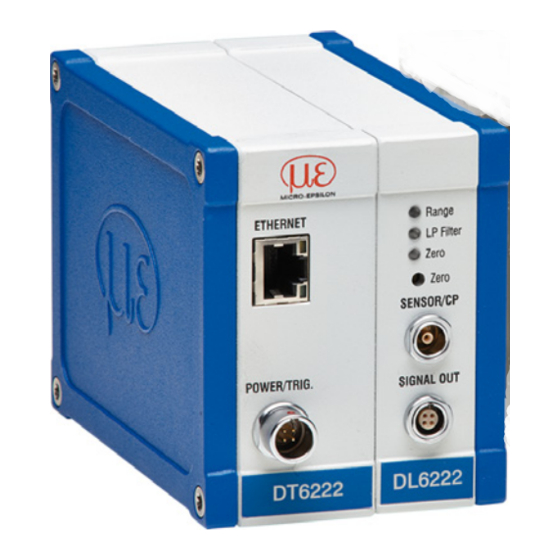
Page 15: Controller
Functional Principle, Technical Data 2.2.3 Controller The capaNCDT 6222 Multi-channel measuring system consists of a basic module DT62xx and one up to four demodulator modules DL62xx, according to requirements. The components are stored in aluminum hous- ings. Basic module Demodulator module(s) Fig. - Page 16 A/D converter. The trim potentiometer zero allows a special zero adjustment of the analog output signals, see Fig. Output voltage can achieve up to 15 VDC, if the sensor is disconnected respectively exceedance of measuring range. capaNCDT 6222 Page 16...
-
Page 17: Technical Data
≤ 2.8 m (mit CCmxx) ≤ 4.0 m (mit CCgxx) ≤ 2.8 m (mit CCmxx) ≤ 4.0 m (mit CCgxx) Trigger TTL, 5 V TTL, 5 V FSO = Full Scale Output 1) A storage temperature of -50 ... +100 °C (-58 to +212 °F) applies for the sensors CSG0.50-CA and CSG1.00-CA -50 capaNCDT 6222 Page 17... -
Page 18: Options
Extended measuring range 2982061 EMR2 DL6222 ○ ○ • (factor: 2) Shortened measuring range 2982062 RMR1/2 DL6222 ○ ○ • (factor: 1/2) • Articles already contain the option ○ Option available - No option available capaNCDT 6222 Page 18... -
Page 19: Delivery
-10 ... +75 °C (+14 to +167 °F) - Humidity: 5 - 95 % RH (non-condensing) 1) A storage temperature of -50 ... +100 °C (-58 to +212 °F) applies for the sensors CSG0.50-CA and CSG1.00-CA -50 capaNCDT 6222 Page 19... -
Page 20: Installation And Assembly
Grub screw Fig. 4 Radial point clamping with grub screw Do not use metal grub screws! > Danger of damaging the sensor capaNCDT 6222 Page 20... -
Page 21: Circumferential Clamping, Cylindric Sensors
Flat sensors are mounted by means of a tap hole for M2 (in case of sensors 0.2 and 0.5 mm) or by a through hole for M2 screws. The sensors can be bolted on top or below. Screwing from above Screwing from bottom capaNCDT 6222 Page 21... -
Page 22: Dimensional Drawings Sensors
Dimensions in mm ø20h7 (.79 dia.) ø10h7 (.394 dia) ø7.7 (0.30 dia.) (inches) Circumferential clamp- ing possible from 3 mm behind the front face. Dimensional drawings of other sensors are ø10h7 (.394 dia.) available on request. capaNCDT 6222 Page 22... - Page 23 Circumferential clamp- ing possible from 3 mm behind the front face. ø20h7 (.79 dia.) ø20h7 (.79 dia.) ø20h7 (.79 dia.) Dimensional drawings of other sensors are available on request. Dimensions in mm (inches), not to scale capaNCDT 6222 Page 23...
- Page 24 Installation and Assembly CSH02-CAmx, CSH1-CAmx, ca. 9.4 (.37) ca. 9.4 (.37) CSH05-CAmx CSH1.2-CAmx ø12g6 (.473 dia.) ø8g6 (.315 dia.) ø7.5 ø11.5 (.30 dia.) (.45 dia.) ø2.2 (.09 dia.) ø2.2 (.09 dia.) capaNCDT 6222 Page 24...
- Page 25 Installation and Assembly CSH2-CAmx appr. 9.4 (.37) ø20g6 (.79) ø19.5 (.77) (.09) ø Dimensions in mm (inches), not to scale capaNCDT 6222 Page 25...
- Page 26 Cylindrical sensors with thread CSE05/M8 CSE1,25/M12 ø10.4 (.41 dia.) ø6.0 ø10 (.24 dia.) Connector side ø5.7 ø9.7 Dimensions in mm (inches) Active measuring surface sensor Dimensional drawings M8x0.5 of other sensors are M12x1 available on request. capaNCDT 6222 Page 26...
- Page 27 Preferred mounting: Sensor Torque Screw the sensor into the sen- CSE05/M8 2.5 Nm max. sor holder. CSE1,5/M12 10 Nm max. Turn the mounting nut on. Do not exceed torques. CSE2/M16 20 Nm max. CSE3/M24 70 Nm max. capaNCDT 6222 Page 27...
- Page 28 9.4 CSH1FL-CRmx, CSH02FL-CRmx, ca. 9.4 (.16) CSH1.2FL-CRmx CSH05FL-CRmx (.37) (.37) (.003) 4 (.16) (.24) 0.1 (.003) (.22) ø3 ø3 (.29) (.12 dia.) (.12 dia.) ø2.2 ø2.2 (.09) (.09) Dimensions in mm (inches), not to scale capaNCDT 6222 Page 28...
- Page 29 Installation and Assembly CSH2FL-CRmx CSH3FL-CRmx (.20) (.79) (.98) appr. 9.4 15.5 (.06) (.61) (.79) (.09) (.37) appr. 9.4 (.37) (.003) (.003) ø3 (.12) ø3 (.12) ø2.2 (.09) ø2.2 (.09) Dimensions in mm (inches), not to scale capaNCDT 6222 Page 29...
-
Page 30: Sensor Cable
The connector locks automatically. The tight fit can be checked by pulling the connector housing (cable bushing). The lock can be released and the connector can be opened by pulling the knurled housing sleeve of the cable bushing. capaNCDT 6222 Page 30... - Page 31 3.1 mm • 0.05 - 0.8 mm 10 mm (perma- (once) CCgxB 2 or 4 m 3.1 mm • 1 ... 10 mm nently) CCgxB/90 2 or 4 m 3.1 mm • 1 ... 10 mm capaNCDT 6222 Page 31...
- Page 32 2.1 mm • 0.05 - 0.8 mm 7 mm (perma- (once) CCmxB 1.4 or 2.8 m 2.1 mm • 1 ... 10 mm nently) CCmxB/90 1.4 or 2.8 m 2.1 mm • 1 ... 10 mm capaNCDT 6222 Page 32...
-
Page 33: Controller
Installation and Assembly Controller 4.4.1 Basic Unit, Demodulator Module 25 (.98) 34 (1.34) 125 (4.92) DT 6222 DL 6222 Fig. 6 Dimensional drawing controller Dimensions in mm (inches), not to scale capaNCDT 6222 Page 33... -
Page 34: Housing Cover
Fig. 7 Dimensional drawing housing cover Dimensions in mm (inches), not to scale The controller is mounted using mounting plates or holding clamps for a mounting on DIN-rail which are included with the conversion kit supplied, see Chap. 1.1. capaNCDT 6222 Page 34... -
Page 35: Insert Demodulator Module
Touch the demodulator modules only at the housing, not at the electronics. This will prevent electro- static discharges on the electronics. Attach the additional demodulator module. Number demodulator Length modules threaded rod M4 59 mm 84 mm 109 mm 134 mm Fig. 8 Mechanical components con- troller capaNCDT 6222 Page 35... - Page 36 Wiring following demodulator module Fig. 9 Wiring demodulator modules Put on the right housing cover (3). Screw the sleeve nuts (4b) on the threaded rods on the right side of the controller and tighten the sleeve nuts. capaNCDT 6222 Page 36...
- Page 37 Press the plugging off assistance with the recess laterally to the connector (5). Loosen the connector with a lever movement. Loosen the other side of the connector in the same way. Fig. 10 Use of the plugging off assistance for the wiring of the demodulator elements capaNCDT 6222 Page 37...
-
Page 38: Ground Connection, Earthing
Different to other systems, with capaNCDT systems is no target earthing necessary The drawing below shows two synchronized capaNCDT sensors, measuring against a mill, see Fig. 11. Due to the unique synchronizing technique of MICRO-EPSILON a special target earthing is not needed in most cases. Sensor Controller sync. -
Page 39: Electrical Connections
Connectivity Options The power supply and the signal output are located at the front side of the controller. Controller EtherCAT (optional) E th LAN-cable RJ-45 connectors CCxxx PS 2020 Ethernet Sensor Ammeter/Voltmeter Fig. 13 Measuring system assembly capaNCDT 6222 Page 39... -
Page 40: Pin Assignment Supply, Trigger
Analog grounds are connected internally. SCACx/4 is a View on solder pin Signal output on 3 m (13.12 ft) long, 4-wire output cable. It is supplied as an side, 4-pole male controller, 4-pole male optional accessory. cable connector cable connector capaNCDT 6222 Page 40... -
Page 41: Operation
Standard bandwidth active SENSOR/CP LP Filter 20 Hz Low-pass filter on the analog outputs enabled POWER/TRIG. SIGNAL OUT Zero poti in basic position (right stop) Zero Zero poti adjusted 1) LP Filter only switchable via Ethernet. capaNCDT 6222 Page 41... -
Page 42: Poti
Signal Signal 10 V 20 mA Range LP Filter Zero Zero SENSOR/CP Displacement Displacement 4 mA 100 % 100 % SIGNAL OUT Zero Zero DL62xx -10 V -12 mA Fig. 14 Zero point shifting with zero-poti capaNCDT 6222 Page 42... -
Page 43: Changing Limit Frequency
The limit frequency can only be changed via the Ethernet interface. Triggering The measuring value output on capaNCDT 6222 is controllable by an external electrical trigger signal or com- mand. Here, only the digital output is affected. Triggering release by:... - Page 44 Software triggering ($GMD). A measuring value is output per channel, as soon as a command is sent. The point of time is not defined as accurately. No trigger is set ex factory. The controller starts the data transfer immediately after the switching on. capaNCDT 6222 Page 44...
-
Page 45: Measurement Averaging
Example with N = 7: 2+3+4+5+6+7+8 gets to Average value n ..0 1 2 3 4 5 6 7 8 3+4+5+6+7+8+9 gets to Average value n +1 ..1 2 3 4 5 6 7 8 9 capaNCDT 6222 Page 45... -
Page 46: Arithmetic Average Value
Then, the average value is provided as the median value. If a even value is selected for the average number N, middle both measuring values are added and divided by two. Example with N = 7: Sorted measuring value Median Sorted measuring value Median capaNCDT 6222 Page 46... -
Page 47: Dynamic Noise Rejection
For that purpose the signal noise is calculated dynamically and measurement changes are only transferred, if they exceed this calculated noise. Thereby at a change in direction of the measurement signal small hystere- sis effects in the size of the calculated noise can occur. capaNCDT 6222 Page 47... -
Page 48: Ethernet Interface
Connect the capaNCDT 6222 to an available Ethernet interface at the PC. Use a crossover cable. For a connection with the capaNCDT 6222 you will require a defined IP address of the network interface card inside the PC. Go to Control Panel\Network Connections. Set up, if applicable, a new LAN connec- tion. - Page 49 Ethernet Interface Define the following address in the properties of the LAN connection: IP address: 169.254.168.1 Subnet mask: 255.255.0.0 Select Properties. Select Internet Protocol (TCP/IP) > Properties. capaNCDT 6222 Page 49...
- Page 50 - by using the web browser. Enter the current IP address into the address bar. Go to the menu Settings > Digital Interfaces > Ethernet settings to set a new IP address, activate DHCP or change the data port. - by using software commands, see Chap. 6.4. - by using the SensorFinder software. capaNCDT 6222 Page 50...
- Page 51 The controller supports UPnP . If you use an operational system with activated UPnP client e. g. standard with Windows 7, the controller is listed in the explorer as a device automatically. This is helpful, if you do not know the IP address of the controller. capaNCDT 6222 Page 51...
-
Page 52: Data Format Of Measuring Values
Measuring values all channels, starting with the lowest channel number Measuring value frame 1 [number 32 bit channels N] „ Measuring value frame 2 [number 32 bit channels N] ..„ Measuring value frame M [number 32 bit channels N] capaNCDT 6222 Page 52... -
Page 53: Settings
Filter/Measuring value averaging: The following filters are selectable: - Moving average - Arithmetic average (only each n value will be output) - Median - Dynamic Noise Rejection The setting for the averaging applies to all channels. capaNCDT 6222 Page 53... - Page 54 60 %, 70 %, 80 %, 90 % and 100 % of the measurement range. The linearization function allows an individual adjustment - of the start of the measurement range, - slope of the characteristic curve (Gain) and - linearity. capaNCDT 6222 Page 54...
- Page 55 50 % 100 % Measurement range Fig. 21 Output characteristic for the measurement The software linearization affects only the values (averaging also), which are output via the Ethernet interface. Mathematic functions: For Calculation of several channels. capaNCDT 6222 Page 55...
-
Page 56: Commands
µs. This is active from then. STI = Set Sample Time Command $STIn<CR> Example: $STI1200<CR> Response $STIn,mOK<CRLF> Example: $STI1200,960OK<CRLF> Index n = designated new sample time in µs (TARGET) m = new sample time in µs (ACTUAL) capaNCDT 6222 Page 56... - Page 57 10.4 Sa/s 64000 15.6 Sa/s 38400 26 Sa/s 32000 31.3 Sa/s 19200 52.1 Sa/s 16000 62.5 Sa/s 9600 104.2 Sa/s 1920 520.8 Sa/s 1041.7 Sa/s 2083.3 Sa/s 3906.3 Sa/s Request sample time Command $STI?<CR> Response $STI?nOK<CRLF> capaNCDT 6222 Page 57...
-
Page 58: Trigger Mode (Trg)
Irrespective of the trigger mode set, a single measured value per channel can be called up by means of a software command, see Chap. 5.5.3. If the trigger mode is turned off, the capaNCDT 6222 will send the mea- surement values without interruption and with the adjusted data rate. -
Page 59: Filter, Averaging Type (Avt)
Number of measuring values used to calculate the average (adjustable from 2 … 8) Command $AVNn<CR> Response $AVNnOK<CRLF> Index n = 2 ... 8 ? = Request averaging number Request averaging number Command $AVN?<CR> Response $AVN?nOK<CRLF> capaNCDT 6222 Page 59... -
Page 60: Channel Status (Chs)
0 = no linearization (default setting) zation mode) 1 = Start of measuring range 2 = 2-point-linearization 3 = 3-point-linearization 4 = 5-point-linearization 5 = 10-point-linearization Request linearization mode Command $LIN?<CR> Response $LIN?n,n,n,nOK<CRLF> (n stands for the linearization type) capaNCDT 6222 Page 60... -
Page 61: Set Linearization Point (Slp)
7 = linearization point at 70 % of the measuring range 8 = linearization point at 80 % of the measuring range 9 = linearization point at 90 % of the measuring range 10 = linearization point at 100 % of the measuring range capaNCDT 6222 Page 61... -
Page 62: Get Linearization Point (Glp)
10 = linearization point at 100 % of measuring range 6.4.10 Status (STS) Reads all settings at once. The individual parameters are separated by a semicolon. The structure of the respective responses corre- sponds to those of the individual requests. Command $STS<CR> Response $STSSTIn;AVTn;AVNn;CHS…;TRG.OK<CRLF> capaNCDT 6222 Page 62... -
Page 63: Version (Ver)
1 up to 8 are multiplied. The range of values of -9.9 up to +9.9 with a decimal place. Structure of factors: Prefix and a one-digit number with a decimal place, example +3.4 capaNCDT 6222 Page 63... - Page 64 Target thickness = +200 % offset (equates to 2 mm) – 1 * channel 1 – 1 * channel 2 Required command: $SMF3:+3FFFFF,-1.0,-1.0,+0.0,+0.0<CR> 3 measured values can be allocated together at most, the different factors have to be +0.0 each. If a math function is set on a channel, the channel status changes onto 2. capaNCDT 6222 Page 64...
-
Page 65: Get Mathematic Function (Gmf)
Structure of factors: Prefix and a one-digit num- ber with a decimal place. Example +3.4. 6.4.14 Clear Mathematic Function (CMF) Deletes the math function on a channel. Command $CMFm<CR> Response $CMFmOK<CRLF> Index m: 1…4 (Channel number) capaNCDT 6222 Page 65... -
Page 66: Ethernet Settings (Ips)
Queries the port number of the data port. Command $GDP<CR> $GDP<Port number>OK<CRLF> Response Example: $GDP10001OK<CRLF> 6.4.17 Set Data Port (SDP) Sets the port number of the data port. Range: 1024 ...65535. Command $SDP<Portnumber><CR> Example: $SDP10001OK<CR> Response $SDP<Portnumber>OK<CRLF> capaNCDT 6222 Page 66... -
Page 67: Access Channel Information (Chi)
6.4.19 Access Controller Information (COI) Reads information of the controller (e.g. serial number). Command $COI<CR> Response $COIANO...,NAM...,SNO...,OPT...,VER...OK<CRLF> Index ANO = Article number NAM = Name SNO = Serial number OPT = Option VER = Firmware version capaNCDT 6222 Page 67... -
Page 68: Login For Web Interface (Lgi)
Changes the password of the device (required for the web interface and the SensorFinder). Command $PWD<oldpassword>,<newpassword>,<newpassword><CR> $PWD<oldpassword>,<newpassword>,<newpassword>OK< CRLF> Response A password can be from 0-16 characters and must contain only letters and numbers. When delivered, no password is assigned. The field can remain empty/blank. capaNCDT 6222 Page 68... -
Page 69: Change Language For The Web Interface (Lng)
Enables/Disables a low pass filter with 20 Hz limit frequency on analog output Command $ALPn<CR> Response $ALPnOK<CRLF> 0 = Low pass filter not active Index 1 = Low pass filter is active Request $ALP? Response $ALP?nOK<CRLF> capaNCDT 6222 Page 69... -
Page 70: Default Messages
IP address of the controller to the list of addresses which should not be routed through the proxy server. The MAC address of the unit can be found on the nameplate of the controller. “ Javascript” must be enabled in the browser so that measurement results can be displayed graphically. capaNCDT 6222 Page 70... - Page 71 Start a web browser on your PC. To achieve a dress: 169.254.168.1. controller with the serial number “01234567”, type in the address bar on your browser “DT6222_01234567”. Interactive web pages for setting the controller and peripherals are now shown in the web browser. capaNCDT 6222 Page 71...
-
Page 72: Access Via Web Interface
6.5.3 Operating Menu, Set Controller Parameter You can program the capaNCDT 6222 at the same time in two different kinds: - Using a web browser via the sensor web interface - With ASCII command set and terminal program via Ethernet (Telnet) -
Page 73: Channel N
Select the designated measuring channel. Select a 3-point linearization type. Adjust the target to 10 % of the measuring range to the sensor. Grey shaded fields require a selection. Dark-bordered fields require Value you to specifie a value. capaNCDT 6222 Page 73... - Page 74 Adjust the target to 50 % of the measuring range to the points. sensor. 50 % Measuring range Sensor Click on the Reset button in web interface in the line 50 %. Adjust the target to 90 % of the measuring range to the sensor. capaNCDT 6222 Page 74...
-
Page 75: Math Function
Value range ±8-point MR max. Data channel 1 / 2 / 3 / 4 Factor measuring channel Value Value range -9,9 ... +9,9 Grey shaded fields require a selection. Dark-bordered fields require Value you to specifie a value. capaNCDT 6222 Page 75... -
Page 76: Measurement Settings
Data Rate frequency, with which data are 104.17 / 520.83 / 1041.67 / 2083.33 / 3906.25 Sa/s Grey shaded output via the Ethernet interface. fields require a selection. Dark-bordered fields require Value you to specifie a value. capaNCDT 6222 Page 76... -
Page 77: Filter Type / Averaging
Chap. 4.7.2 or by the command $ GMD, see Chap. 6.4.3. If the trigger mode is turned off, the capaNCDT 6222 will send the measuring values without interruption and with the adjusted data rate. Rising edge A measuring value is output per edge. -
Page 78: System Settings
The current user level remains after leaving the web interface of restarting the controller. User Professional Password required View settings The following functions are accessible Change settings, linearization, for the user: analog output, change password Start measuring Scaling diagrams Fig. 25 Permissions within the user hierarchy capaNCDT 6222 Page 78... -
Page 79: Password
With DHCP it may be necessary to enable the controller MAC ad- Dark-bordered MAC address Value dress. fields require UUID Value Value you to specifie Data port Value Setting the port on the measurement server a value. capaNCDT 6222 Page 79... -
Page 80: Import, Export
Address type (static, DHCP), IP address, settings operating mode after start When importing settings, consider if you want to replace the current con- troller and/or Ethernet settings. Choose the desired import option in the settings section. capaNCDT 6222 Page 80... -
Page 81: Firmware Update
Fast events are displayed on a suitable external recorder (oscilloscope, recorder, transient recorder). - Compensation method for constant or slowly changing distances. Compensation is carried out with the “zero” potentiometer until the output signal is 0 Volt. Sensitivity is not affected by doing this. capaNCDT 6222 Page 81... -
Page 82: Operation And Maintenance
94496 Ortenburg / Germany identifiable, the whole measuring system must be sent back for repair or replacement to Tel. +49 (0) 8542 / 168-0 Fax +49 (0) 8542 / 168-90 info@micro-epsilon.com www.micro-epsilon.com capaNCDT 6222 Page 82... -
Page 83: Liability For Material Defects
Within this period, defective parts, except for wearing parts, will be repaired or replaced free of charge, if the device is returned to MICRO-EPSILON with shipping costs prepaid. Any damage that is caused by improper handling, the use of force or by repairs or modifications by third parties is not covered by the liability for mate- rial defects. -
Page 84: Appendix
The conversion kit is contained in the scope of supply, see Chap. 3.1. Ground terminal ø 4,3 mm (.17.3 dia.) Ground connection Mounting clamps for mounting 20 x 0.8 mm/ CK75G hardened/ on DIN-rail plated Mounting clamps for mounting on DIN-rail capaNCDT 6222 Page 84... - Page 85 Mounting plate Aluminum / powder-coated Plugging off assistance for con- nector (.12) (.39) (.03) (.79) Dimensions in mm (inches), not to scale Further more, the conversion kit contains sleeve nuts, threaded rods in different lengths and screws. capaNCDT 6222 Page 85...
-
Page 86: Pc6200-3/4
Optional Accessories Micrometer calibration fixture, MC2.5 setting range 0 - 2.5 mm, reading 0.1 μm, for sensors CS005 to CS2 Digital micrometer calibration fixture, MC25D setting range 0 - 25 mm, adjustable zero point for all sensors capaNCDT 6222 Page 86... - Page 87 Appendix| Accessories, Service Vacuum feed through, SWH.OS.650.CTMSV 34 (1.34) Max. leak rate 1x10e- mbar · l s Compatible with connector type B M10x0.75 (.08) max. 17 (.67) capaNCDT 6222 Page 87...
- Page 88 Vacuum feed through triax screwable Max. leak rate 1x10e-9 mbar · l s 25 (.98) Compatible with connector type B ø13.50h6 SW11 All vacuum feed throughs are compatible to the connectors type B, see Chap. 4.3. capaNCDT 6222 Page 88...
-
Page 89: A 1.5 Service
Power supply for mounting on DIN-rail PS2020 input 230 VAC (115 VAC) output 24 VDC / 2.5 A; L/W/H 120 x 120 x 40 mm A 1.5 Service Function and linearity check-out, inclusive 11-point protocol with grafic and post-calibration. capaNCDT 6222 Page 89... -
Page 90: Factory Setting
- LP filter 20 Hz = Off - Filter = Off - Linearization = Off - Trigger mode = Off - Math functions = Off - IP address = Static IP (169.254.168.150) - Data port = 10001 capaNCDT 6222 Page 90... -
Page 91: Tilt Angle Influence On The Capacitive Sensor
Angle [°] Fig. 28 Example of measuring range deviation in the case of a sensor distance of 100 % of the measu- ring range capaNCDT 6222 Page 91... -
Page 92: Measurement On Narrow Targets
Fig. 31 Example of measuring range deviation in the Fig. 32 Signal change in the case of displacement of case of a sensor distance of 100 % of the measu- thin targets in the opposite direction to the measure- ring range ment direction capaNCDT 6222 Page 92... -
Page 93: Measurements On Balls And Shafts
Figures give an influence example shown on the sensors CS02 and CS1 in the case of different sensor distances to the target as well as target diameters. As this results from internal simulations and calcula- tions, please request for detailed information. capaNCDT 6222 Page 93... - Page 94 MICRO-EPSILON MESSTECHNIK GmbH & Co. KG X9751360-A042020SWE Koenigbacher Str. 15 · 94496 Ortenburg / Germany MICRO-EPSILON MESSTECHNIK Tel. +49 (0) 8542 / 168-0 · Fax +49 (0) 8542 / 168-90 *X9751360-A04* info@micro-epsilon.com · www.micro-epsilon.com...
Need help?
Do you have a question about the capaNCDT 6222 and is the answer not in the manual?
Questions and answers