MICRO-EPSILON CS005 Operating Instructions Manual
Hide thumbs
Also See for CS005:
- Instruction manual (68 pages) ,
- Operating instructions manual (94 pages) ,
- Operating instructions manual (116 pages)
Table of Contents
Advertisement
Quick Links
Advertisement
Table of Contents

Related Manuals for MICRO-EPSILON CS005


Summary of Contents for MICRO-EPSILON CS005
- Page 1 Operating Instructions capaNCDT 6500 CS005 CSH05FL CSH1.2 CSE3/M24 CS02 CS08 CSH1.2FL CSH3FL CSH02 CSH02FL CSE1 CSE2 CS10 CS05 CSE1,25/M12 CSE2/M16 CSG0.50-CAm2.0 CSE05 CSH1 CSH2 CSG1.00-CAm2.0 CSE05/M8 CSH1FL CSH2FL CSH05 CS1HP...
- Page 2 MICRO-EPSILON MESSTECHNIK GmbH & Co. KG Koenigbacher Str. 15 94496 Ortenburg / Germany Tel. +49/8542/168-0 Fax +49/8542/168-90 e-mail info@micro-epsilon.com www.micro-epsilon.com EtherCAT® is registered trademark and patented technology, licensed by Beckhoff Automation GmbH, Germany.
-
Page 3: Table Of Contents
Contents Safety ............................5 Symbols Used ..........................5 Warnings ............................5 Notes on CE Marking ........................5 Intended Use ............................ 6 Proper Environment ......................... 6 Functional Principle, Technical Data ..................7 Measuring Principle .......................... 7 Structure ............................7 2.2.1 Sensors .............................. 8 2.2.2 Sensor Cable ............................. - Page 4 6.4.11 Get Linearization Point (GLP) ......................41 6.4.12 Status (STS) ............................. 41 6.4.13 Version (VER) ........................... 41 6.4.14 Display Setups (DIS) ........................41 6.4.15 Load Factory Setting (FDE) ......................42 6.4.16 SMF = Set Mathematic Function (SMF) ..................42 6.4.17 Get Mathematic Function (GMF) .....................
-
Page 5: Safety
Products which carry the CE mark satisfy the requirements of the EU directives cited and the European harmonized standards (EN) listed therein. The EU Declaration of Conformi- ty is available to the responsible authorities according to EU Directive, article 10, at: MICRO-EPSILON MESSTECHNIK GmbH & Co. KG Koenigbacher Str. 15... -
Page 6: Intended Use
Safety Intended Use The DT6530 measuring system is designed for use in industrial and laboratory areas. It is used for - displacement, distance, profile, thickness and surface measurement - for in-process quality control and dimensional testing The system must only be operated within the limits specified in the technical data, see 2.3. -
Page 7: Functional Principle, Technical Data
Functional Principle, Technical Data Functional Principle, Technical Data Measuring Principle The principle of capacitive distance measurement with the capaNCDT system is based on the principle of the parallel plate capacitor. For conductive targets, the sensor and the target opposite form the two plate electrodes. If a AC current with a constant ampli- tude flows through the sensor capacitor, the amplitude of the AC voltage at the sensor is proportional to the distance between the capacitor electrodes. -
Page 8: Sensors
In the case of insulators the dielectric constant and the target thickness also play an important role. Sensors for metal targets Sensor model Measuring range Min. target diameter CS005 0.05 mm 3 mm CS02 0.2 mm 5 mm CS05 0.5 mm... -
Page 9: Sensor Cable
Functional Principle, Technical Data Sensors for insulating targets The sensors also measure reliable against insulating materials. The linear behavior for this category of targets is achieved by special linearization, see 5.4. The measuring rang- es of the respective sensors depend on the e of the target. -
Page 10: Controller Housing
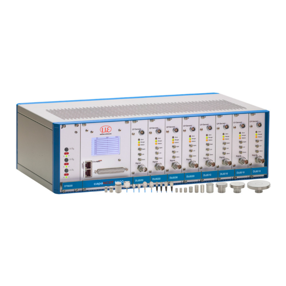
Functional Principle, Technical Data 2.2.5 Controller Housing The capaNCDT 6500 multichannel rack is constructed for up to eight channels, the capaNCDT 6500C multichannel rack is constructed for up to two channels which are all synchronized. Power supply Display board Demodulator Fig. -
Page 11: Dd6500 Display Board With Ethernet Interface
Functional Principle, Technical Data 2.2.7 DD6500 Display Board with Ethernet Interface The display board DD6500 serves to display and output of signal. The measuring values can be read in percent of all eight channels on display. The analog output signals (volt- age and current output) the trigger input and the synchronization input/output are locat- ed on the 37-pol-Sub-D connector. -
Page 12: Technical Data
Functional Principle, Technical Data Technical Data Controller type DT6530 DT6530 DL6530 DL6510 mit CPM6011 DL6510 with CP6001 Resolution, static (2.6 Hz) 0.000075 % FSO 0.0006 % FSO (100 Hz) 0.0003 % FSO 0.0025 % FSO Resolution, (1 kHz) 0.0009 % FSO 0.007 % FSO dynamic (8.5 kHz) -
Page 13: Delivery
Delivery Delivery Unpacking 1 Housing with power supply, oscillator and display board n Demodulators n Sensors n Sensor cable with connector n Preamplifier (only DL6510) n Preamplifier cable (only DL6510) 1 Instruction manual 37-pole Sub-D connector, mains connection cable, network cable (crossover cable) n = Number of displacement measuring channels Remove the parts of the system carefully from the packaging and transport them in such a way that they are not damaged. -
Page 14: Installation And Assembly
Installation and Assembly Installation and Assembly Precautionary Measures No sharp-edged or heavy objects may get into contact with the sensor cable sheath. Protect the cable In pressurized rooms against pressure loads. Avoid kinks in any case. Check the connections for tight fit. A damaged cable cannot be repaired. -
Page 15: Dimensional Drawing Sensors
Installation and Assembly 4.2.4 Dimensional Drawing Sensors Cylindric sensors CS005 CS02 CS05 CSE05 CS08 ø3 (0.118 dia.) ø5.7 (.22) ø10h7 ø6f7 ø6f7(.236 dia.) (.394 dia.) (.24 dia.) ø6f7 (.236 dia.) ø8f7 (.314 dia.) CSE2 CS1HP CSE1 M=1:2 ø14h7 (0.55 dia.) ø8f7 (0.31 dia.) - Page 16 Installation and Assembly CSH02-CAmx CSH1-CAmx ca. 9.4 (.37) ca. 9.4 (.37) CSH05-CAmx CSH1.2-CAmx ø12g6 (.473 dia.) ø8g6 (.315 dia.) ø7.5 ø11.5 (.30 dia.) (.45 dia.) ø2.2 (.09 dia.) ø2.2 (.09 dia.) CSH2-CAmx appr. 9.4 (.37) ø20g6 (.79) ø19.5 (.77) (.09) ø...
- Page 17 Installation and Assembly Cylindrical sensors with thread CSE1,25/M12 CSE05/M8 ø10.4 (.41 dia.) ø10 ø6.0 (.24 dia.) ø9.7 ø5.7 M8x0.5 M12x1 CSE2/M16 CSE3/M24 WS14 WS18 ø14.4 ø20.6 (.57 dia.) (.81 dia.) ø14.0 ø20.0 ø13.7 ø19.2 M16x1 M24x1.5 Preferred mounting: Sensor Torque Screw the sensor into the CSE05/M8 2.5 Nm max.
- Page 18 Installation and Assembly Flat sensors ca. 9.4 (.37) ca. 9.4 (.37) CSH02FL-CRmx CSH1FL-CRmx (.16) CSH05FL-CRmx CSH1.2FL-CRmx (.003) (.16) (.24) (.003) (.16) ø3 ø3 (.22) (.29) (.12 dia.) (.12 dia.) ø2.2 ø2.2 (.09) (.09) CSH2FL-CRmx CSH3FL-CRmx (.98) (.79) (.20) (.20) 15.5 ca.
-
Page 19: Sensor Cable
Installation and Assembly Sensor Cable The sensor is connected to the signal conditioning electronics by the sensor cable. The con- nection is made by simple plugging. The connector locks automatically. The tight fit can be checked by pulling the connector housing (cable bushing). The lock can be released and the connector can be opened by pulling the knurled housing sleeve of the cable bushing. -
Page 20: Preamplifier Cp6001 And Cpm6011
Installation and Assembly Preamplifier CP6001 and CPM6011 (4.49) (.36) 34.6 (.18) (1.36) Fig. 12 Preamplifier CP6001 (3.15) (.25) (2.64) (1.02) Fig. 13 Preamplifier CPM6011 Mounting preamplifier with mounting device (CP6001) Remove the four black protecting caps at the housing screws, dimension 73. Remove the four housing screws. -
Page 21: Preamplifier Cable Cax
Installation and Assembly Preamplifier Cable CAx x = cable length 5 ... 25 m (standard 5 m) Controller Text Text Text Model 6530c (maximum 2 channels) 214 (8) 236 (9) 6530 (maximum 8 channels) 427 (17) 449 (18) Dimensions in mm (inches), not to scale R5.2 8.8 (0.35) 58.6... -
Page 22: Power Supply
Fig. 14 shows two synchronized capaNCDT sensors, measuring against a mill. Due to the unique synchronizing technique of Micro-Epsilon is in most cases a special target earthing not needed. Sensor Controller sync. -
Page 23: Pin Assignment
Installation and Assembly Pin Assignment This module is used for signal display and output when measuring, calibrating or check- ing the system. The output voltage can be tapped at the BNC connectors of the de- modulator boards additionally. Fig. 19 Measuring unit with controller, preamplifier, and sensors 37-pole Sub-D connector: U-Out Channel 1 Trigger_In... -
Page 24: Synchronization
Installation and Assembly 4.10 Synchronization Several measuring systems capaNCDT 6500 can simultaneously be used as multi-chan- nel system. With the synchronization of the systems, a mutual influence to the sensors is avoided Plug the synchronize cable SC6000-x (accessory) into the female connector SYNC OUT (synchronization output) at the controller 1. -
Page 25: Operation
Operation Operation Initial Operation NOTICE Pay attention to switching on the device, that you have plugged-in all boards in the des- Do not plug-in or unplug ignated positions. any board during the Let warm up the measuring system for about 15 minutes before you run a measuring or operation! calibration. -
Page 26: Do6510
Operation 5.2.3 DO6510 The optional analog output card DO6510 outputs digitally computed measurement signals in analog form. The DO6510 includes 3 analog outputs which can output signals either in the range 0 … 10 V, ±5 V, or in the range 4 … 20 mA. A rotary switch to the side of the slot is used to select the type of output. -
Page 27: Dl6530/6510
Operation 5.2.4 DL6530/6510 Gain, zero and linearity of a measuring channel are adjusted with the “Gain“, “Zero“ and “Lin“ trimmer potentiometers, see Fig. 26. The setting range is approximately 18 turns per potentiometer. The end settings at the left and right stops are recognizable by a slight click. - Page 28 Operation Trimmer Zero: Turn the trim-pot clockwise to shift the characteristic line to the left. Zero Displacement EMR = End of measuring range The Zero-Poti affects only the analog outputs, not yet the digital measuring values. Target selection Use the slide switch, see Fig.
-
Page 29: Calibration With Metal Targets
Operation Calibration with Metal Targets Preconditions: - Specific resistance of the target < 100 Ωcm. - Slide switch on the demodulator in position Cond. (Conductor, see Fig. For metallic targets the demodulator´s linearization function is switched off since a linear characteristic is already available automatically on account of the measuring principle and sensor construction. -
Page 30: Linearity Adjustment And Calibration With Insulator Targets
Adjustment takes place at defined distances which are prescribed by a reference. A special micrometer calibration device with a non-rotating micrometer spindle (for example MC25 from MICRO-EPSILON) has proved to be particu- larly suitable. Spacer discs are not suitable. - Page 31 Operation Step 2: Linearity The measured value differences B-A and C-B are calculated from the fixed measuring points A B C and compared with each other. The setting of the linearity potentiometer is now altered until B-A and C-B are identical. If the setting is not valid, you can do the following: Add with the trimmer “Lin“...
-
Page 32: Triggering
Operation Triggering The DT6530 can be operated - by a trigger input, see Fig. 30, or - via a software command, see 6.4.3. In addition the trigger mode must be activated and a data rate, which is greater than the maximum trigger frequency, must be set. -
Page 33: Ethernet Interface
Ethernet interface. For that purpose, use the web interface, the runtime version or your own program. Micro-Epsilon supports you by the driver MEDAQLib, containing all commands for the capaNCDT 6500. You can find the current driver routine including documents at: www.micro-epsilon.com/download... - Page 34 Ethernet Interface Select Internet Protocol (TCP/IP) > Properties. In order to be able to use the Ethernet interface, there must be a demodulator mod- ule in channel 1 as this one determines the cycle for all channels! By default, the IP address of the controller is set to 169.254.168.150. Communication with the controller is done on the data port 10001 for measurement transmission.
-
Page 35: Data Format Of Measuring Values
Ethernet Interface Data Format of Measuring Values The measuring value is made up of 4 consecutive bytes: Bit 1 Bit 2 Bit 3 Bit 4 Bit 5 Bit 6 Bit 7 Bit 8 1. Byte 1 (Start) Channel number ( 1 ... 8 ) Vz-Bit MSB 2. -
Page 36: Commands
Ethernet Interface The two correction curves for the 3-point-linearization use restart points at 10 % and 50 %, 50 % and 90 % of the measurement range. The four correction curves for the 5-point-linearization use data points at 10 % and 30 % , 30 % and 50 %, 50 % and 70 %, 70 % and 90 % of the measurement range. -
Page 37: Data Rate (Sra = Set Sample Rate)
Ethernet Interface 6.4.1 Data Rate (SRA = Set Sample Rate) Changes the data rate for all channels which are used to transmit the measurement values. SRA = Set Sample Rate Command $SRAn<CR> Response $SRAnOK<CRLF> Index n = 0...13 Request data rate Command $SRA?<CR>... -
Page 38: Get Measured Data (Gmd)
Ethernet Interface 6.4.3 Get Measured Data (GMD) In the trigger mode, one measured data is transmitted per channel. Command $GMD<CR> Response $GMDOK<CRLF> + Measuring value in binary mode (format as in operating mode “continuous transmission“) 6.4.4 Averaging Type (AVT) Mode of measurement averaging Command $AVTn<CR>... -
Page 39: Dynamic Noise Rejection
Ethernet Interface Example with N = 3: 2+3+4 ..0 1 2 3 4 ... gets to Average value n 5+6+7 ..3 4 5 6 7 ... gets to Average value n + 1 Median The Median is formed from a pre-selected number N of measuring values. The incoming measuring values are sorted anew after each measurement. -
Page 40: Mode Of Linearization (Lin)
Ethernet Interface 6.4.9 Mode of Linearization (LIN) Specifies the linearization type for each channel. The linearization type can be set for each channel. The index m stands for channel num- ber, the index n for the linearization type. Command $LINm:n<CR> (for example: $LIN5:2<CR> = 2-point-linearization for channel 5) Response $LINm:nOK<CRLF>... -
Page 41: Get Linearization Point (Glp)
Ethernet Interface 6.4.11 Get Linearization Point (GLP) Reads out the linearization point. The value is output as a 6-digit number in hex format (000000 to FFFFFF). Command $GLPm:n<CR> (for example: $GLP5:3<CR> = linearization point at 30 % of channel 5) Response $GLPm:n,……OK<CRLF>... -
Page 42: Load Factory Setting (Fde)
Ethernet Interface 6.4.15 Load Factory Setting (FDE) Loads the factory setting. Command $FDE<CR> Response $FDESRAn;AVTn;AVNn;CHS...;CHT...;TRG.;LINn,n,n,n,n,n,n,n;DISa,bOK <CRLF> Factory settings: - Data rate = 100 Sa - Filter = Off - Linearization = Off - Transmit channels = All - Trigger mode = Off - Display = All channels, non-linearized measuring values... -
Page 43: Get Mathematic Function (Gmf)
Ethernet Interface 6.4.17 Get Mathematic Function (GMF) Reads out the math function of a channel. Command $GMFm<CRLF> Response $GMFm:Offset,Factor1,Factor2,Factor3,Factor4,Factor5,Factor6,Factor7,- Factor8OK<CRLF> Index m: 1…8 If a channel is selected, which is already (Channel number) reserved by electronics, the result of the math function is now transmitted instead of the mea- sured value. -
Page 44: Query Data Port (Gdp = Get Dataport)
Ethernet Interface 6.4.21 Query Data Port (GDP = Get Dataport) Queries the port number of the data port. Command $GDP<CRLF> $GDP<Portnumber>OK<CRLF> Response Example: $GDP10001OK<CRLF> 6.4.22 Set Data Port (SDP = Set Dataport) Sets the port number of the data port. Range: 1024 ...65535. Command $SDP<Portnumber><CRLF>... -
Page 45: Change Password (Pwd = Password)
Ethernet Interface 6.4.27 Change Password (PWD = Password) Changes the password of the device (required for the web interface and the sensor- TOOL). Command $PWD<oldpassword>,<newpassword>,<newpassword><CR> $PWD<oldpassword>,<newpassword>,<newpassword>OK< CRLF> Response A password can be from 0-16 characters and must contain only letters and numbers. -
Page 46: Control Via Ethernet
“01234567”, type in the address bar on your browser “DT6530_01234567”. Interactive web pages for setting the controller and peripherals are now shown in the web browser. The sensorTOOL program is available online at https://www.micro-epsilon.com/download/software/sensorTool.exe. capaNCDT 6500 Page 46... -
Page 47: Access Via Web Interface
EtherCAT Interface 6.5.2 Access via Web Interface 4289 Fig. 36 First interactive web page after calling the IP address Use the upper navigation bar to access additional features (e. g. settings). All settings on the web page are applied immediately in the controller. Parallel operation with web interface and Telnet commands is is possible;... -
Page 48: Change Interface
In the case of faults the cause of which is not clearly identifiable, the whole measuring system must be sent back for repair or replacement to MICRO-EPSILON MESSTECHNIK GmbH & Co. KG Koenigbacher Str. 15... -
Page 49: Liability For Material Defects
Within this period, defective parts, except for wearing parts, will be repaired or replaced free of charge, if the device is returned to MICRO-EPSILON with shipping costs prepaid. Any damage that is caused by improper handling, the use of force or by repairs or mod- ifications by third parties is not covered by the liability for material defects. -
Page 50: A 1 Optional Accessory
Decommissioning, Disposal Appendix Optional Accessory MC2.5 Micrometer calibration device, setting range 0 - 2.5 mm, reading 0.1 µm, f or sensors S 601-0.05 to CS 2 MC25D Digital micrometer calibration device, setting range 0 - 25 mm, adjustable zero-point, for all sensors SC3100-x Synchronization cable, cable length x = 0.3 or 1 m... - Page 51 Appendix | Optional Accessory SWH.OS.650.CTMSV Vacuum feed through, 34 (1.34) Max. leak rate 1x10e-7 mbar · l s- 2 (0.08) M10x0.75 Compatible with connector type B (M10x0.03) max. 17 (max. 0.67) Leak rate <1 * 10e-7 mbar * l / s UHV/B Vacuum feed through triax weld- able...
-
Page 52: A 2 Services
Appendix | Services Services Function and linearity check-out, inclusive 11-point-protocol with grafic and post-calibration. Factory Setting - Data rate = 100 Sa/s - Filter = Off - Linearization = Off - Transmit channels = All - Trigger mode = Off - Display = All channels, non-linearized measuring values - Math functions... -
Page 53: A 4.2 Measurements On Balls And Shafts
Appendix | Tilt Angle Influence on the Capacitive Sensor 50 % 45 % 40 % 35 % 30 % 3 mm 25 % z constant 4 mm 20 % 6 mm 15 % 10 % Movement 8 mm y >8 mm in x-direction Target dispacement perpendicular to the sensor axis [mm] Fig. -
Page 54: A 5 Ethercat Documentation
Appendix | EtherCAT Documentation EtherCAT Documentation EtherCAT® is, from the Ethernet viewpoint, a single, large Ethernet station that transmits and receives Ethernet telegrams. Such an EtherCAT system consists of an EtherCAT master and up to 65535 EtherCAT slaves. Master and slaves communicate via a standard Ethernet wiring. On-the-fly processing hardware is used in each slave. -
Page 55: A 5.1.3 Addressing And Fmmus
Appendix | EtherCAT Documentation - FRMW (Configured address read multiple write, Reading of a physical area with fixed addressing, multiple writing) A 5.1.3 Addressing and FMMUs In order to address a slave in the EtherCAT® system, various methods from the master can be used. -
Page 56: A 5.1.5 Ethercat State Machine
Appendix | EtherCAT Documentation A 5.1.5 EtherCAT State Machine The EtherCAT® state machine is implemented in each EtherCAT®. Directly after switch- ing on the capaNCDT 6500, the state machine is in the “Initialization“ state. In this state, the master has access to the DLL information register of the slave hardware. The mail- box is not yet initialized, i.e. -
Page 57: A 5.1.8 Service Data Sdo Service
Appendix | EtherCAT Documentation A 5.1.8 Service Data SDO Service Service Data Objects (SDOs) are primarily used for the transmission of data that are not time critical, e.g. parameter values. EtherCAT specifies the SDO services as well as the SDO information services: SDO services make possible the read/write access to entries in the CoE object directory of the device. -
Page 58: A 5.2.2 Manufacturer Specific Objects
Appendix | EtherCAT Documentation Object 1A00h: TxPDO Mapping 1A00 RECORD TxPDO Mapping Subindices Number of entries Unsigned8 Subindex 001 0x0000:00 Unsigned32 Subindex 002 0x6020:03 Unsigned32 Subindex 003 0x6020:08 Unsigned32 Subindex 004 0x6020:09 Unsigned32 Subindex 005 0x6020:0A Unsigned32 Subindex 006 0x6020:0B Unsigned32 Subindex 007 0x6020:0C... - Page 59 Appendix | EtherCAT Documentation Object 2020h: Channel information 2020 RECORD Channel 1 info Subindices Number of entries Unsigned8 Name DL6500 Visible String ro Serial No xxxxxxxx Unsigned32 Status Active Enum Range Unsigned32 Unit µm Enum Data format zero value 0 Signed32 Data format end value 16777215...
- Page 60 Appendix | EtherCAT Documentation Object 6020h: Measuring values 6020 RECORD Measuring values Subindices Number of entries Unsigned8 Counter xxxx Signed32 Channel 1 xxxx Signed32 Channel 2 xxxx Signed32 Channel 3 xxxx Signed32 Channel 4 xxxx Signed32 Channel 5 xxxx Signed32 Channel 6 xxxx Signed32...
-
Page 61: A 5.3 Measurement Data Format
EtherCAT Configuration with the Beckhoff TwinCAT©-Manager For example the Beckhoff TwinCAT Manager can be used as EtherCAT Master. Copy the device description file (EtherCAT®-Slave Information) Micro-Epsilon. xml in the directory \\TwinCAT\IO\EtherCAT before the measuring device can be configured via EtherCAT®. - Page 62 Appendix | EtherCAT Documentation The current status should be at least PREOP, SAFEOP or OP on the Online side. Example for a complete object directory (subject to change without prior notice). capaNCDT 6500 Page 62...
- Page 63 Appendix | EtherCAT Documentation On the Process data side the PDO allocations can be read from the device. The selected measuring values are transmitted as process data in the status SAFEOP and OP. capaNCDT 6500 Page 63...
-
Page 64: A 6 Thickness Measurement
Appendix | Thickness Measurement Thickness Measurement A 6.1 General This chapter describes a thickness measurement with two oppositely mounted sen- sors. The display on controller shows the distance values of the individual sensors. The distance between the two sensors to one another comes as a base into the thickness measurement. -
Page 65: A 6.3 Data Format, Word Length
Appendix | Thickness Measurement If no module is on the output channel, the individually set value is overwritten again with 10.000 when the system restarts. If the word length of the data channel is optimally uti- lized and therefore a smaller measuring range is adjusted, this setting must be reset after the restart. -
Page 66: A 6.5 Interpretation Of The Measuring Values
Appendix | Thickness Measurement Formula for the thickness measurement: Data channel = Offset + Measuring channel 1 + Measuring channel 2 The result of the mathematic function is output via the Ethernet interface. It is not shown on display of the DD6530. The output as analog signal is possible via the optional available analog output card DO6510, see 5.2.3 or EtherCAT and an appro-... - Page 67 Appendix | Thickness Measurement Sensor 1 Sensor 1 Sensor 1 Sensor 1 2 mm 0.8 mm 1.2 mm 2 mm 2 mm 1.2 mm 2 mm 0.8 mm Sensor 2 Sensor 2 Sensor 2 Sensor 2 Offset 5,200 µm 4,000 µm 4,000 µm 4,000 µm Measuring range...
- Page 68 MICRO-EPSILON MESSTECHNIK GmbH & Co. KG Koenigbacher Str. 15 · 94496 Ortenburg / Germany X9751294-A132032HDR Tel. +49 (0) 8542 / 168-0 · Fax +49 (0) 8542 / 168-90 info@micro-epsilon.com · www.micro-epsilon.com MICRO-EPSILON MESSTECHNIK...
Need help?
Do you have a question about the CS005 and is the answer not in the manual?
Questions and answers