Leica 3D Disto User Manual
Three-dimensional measuring and projection system
Hide thumbs
Also See for 3D Disto:
- User manual (219 pages) ,
- Quick start manual (18 pages) ,
- User manual (192 pages)
Table of Contents
Advertisement
Quick Links
Advertisement
Table of Contents

Related Manuals for Leica 3D Disto


Summary of Contents for Leica 3D Disto
- Page 1 Leica 3D Disto User Manual Version 6.0 English...
- Page 2 Leica USB memory stick • https://myworld.leica-geosystems.com • Leica Geosystems On the last page of this manual, you can find the address of Leica Geosystems address book headquarters. For a list of regional contacts, please visit http://leica-geosystems.com/contact-us/sales_support. myWorld@Leica Geosystems (https://myworld.leica-geosystems.com) offers a wide range of services, information and training material.
- Page 3 Description myProducts Add all products that you and your company own and explore your world of Leica Geosystems: View detailed information on your products and update your products with the latest software and keep up- to-date with the latest documentation.
-
Page 4: Table Of Contents
Power Supply 3D Disto Software 2.5.1 Software Concept 2.5.2 User Interface Instrument Setup Setting Up 3D Disto Connecting the 3D Disto to a Windows Device Assistant Tilt Sensor Device Configuration and Menu Settings Data Management 3.6.1 File Manager 3.6.2 Export and Import of Data... - Page 5 Location Tool Kit 6.5.1 Comfort Plumbing 6.5.2 Comfort Targeting 6.5.3 Comfort Level 6.5.4 Meter Mark 6.5.5 Height Tracking 6.5.6 Parallel Line Error Messages Check & Adjust Overview Tilt Sensor Calibration Crosshairs Offset V-Index Error Reset to Factory Settings Instrument Protection (Theft Protection) Care and Transport 10.1 Transport...
-
Page 6: Safety Directions
Safety Directions General Introduction Description The following directions enable the person responsible for the product, and the person who actually uses the equipment, to anticipate and avoid opera- tional hazards. The person responsible for the product must ensure that all users understand these directions and adhere to them. -
Page 7: Definition Of Use
Responsibilities Manufacturer of the Leica Geosystems AG, CH-9435 Heerbrugg, hereinafter referred to as Leica product Geosystems, is responsible for supplying the product, including the User Manual and original accessories, in a safe condition. -
Page 8: Hazards Of Use
To be familiar with local regulations relating to safety and accident pre- • vention. To inform Leica Geosystems immediately if the product and the applica- • tion becomes unsafe. To ensure that the national laws, regulations and conditions for the oper- •... - Page 9 CAUTION Not properly secured accessories If the accessories used with the product are not properly secured and the product is subjected to mechanical shock, for example blows or falling, the product may be damaged or people can sustain injury. Precautions: ▶...
-
Page 10: Laser Classification
Product-specific treatment and waste management information can be received from your Leica Geosystems distributor. CAUTION Changes or modifications not expressly approved by Leica Geosystems for compliance could void the user's authority to operate the equipment. WARNING Improperly repaired equipment Risk of injuries to users and equipment destruction due to lack of repair knowledge. -
Page 11: Integrated Distance Meter
IEC TR 60825-14 (2004-02). 1.6.2 Integrated Distance Meter Integrated Distance The Leica 3D Disto produces a visible laser beam which emerges from the Meter front of the instrument. The laser product described in this section is classified as laser class 2 in accordance with: IEC 60825-1 (2014-05): “Safety of laser products”... - Page 12 Although the product meets the strict regulations and standards which are in force in this respect, Leica Geosystems cannot completely exclude the possib- ility that function of the product may be disturbed in such an electromagnetic environment.
-
Page 13: Conformity To National Regulations
Precautions: ▶ Although the product meets the strict regulations and standards which are in force in this respect, Leica Geosystems cannot completely exclude the possibility that other equipment can be disturbed or that humans or animals can be affected. ▶... -
Page 14: Ised Statement, Applicable In Canada
This device is granted pursuant to the Japanese Radio Law ( • 電波法 This device should not be modified (otherwise the granted designation • number will become invalid). 1.8.4 Singapore Leica 3D Disto: ☞ Complies with IMDA Standards DB102875 Safety Directions... -
Page 15: Labelling
Labelling Labelling 3D Disto SWISS Technology by Leica Geosystems Art.No.: 844709 Power: 24V / 2.5A Contains IC: 5123A-BGTWF111 Contains FCC ID: QOQWF111 Patents: US 8279421, US 6864966, US 7030969, US 6859744, US 6463393 This device complies with part 15 of the FCC Rules. Operation is subject to the following two conditions:... -
Page 16: Description Of The System
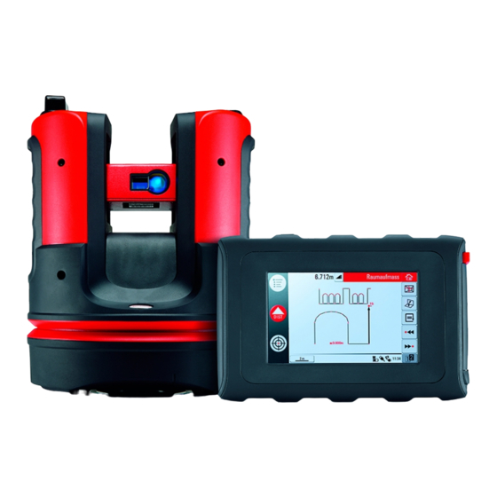
3D Disto General The Leica3D Disto is a three-dimensional measuring and projection system. To Description operate the 3D Disto you need a Windows device. To perform certain func- tions you can also use the RM100 Remote Control. 010714_001 3D Disto... -
Page 17: Instrument Components
Ruler for offset points 3D Disto power supply 010993_001 Instrument Components 2.3.1 3D Disto Motor-driven Part LEDs for 3D Disto status ON/OFF button Grips to hold the instrument Infrared (IR) interface WLAN interface Laser distance meter with Pointfinder Circular bubble... - Page 18 • continuously: 3D Disto is booting. Orange LED flashes: Self-levelling • procedure is running or tilt > 3°. Green LED flashes: 3D Disto is ready • for measurement. Tilt sensor is on. Orange LED lights up continuously: • An error occurred. Refer to "7 Error Messages".
-
Page 19: Rm100 Remote Control
Control LED 010737_001 Navigation Buttons The RM100 Remote Control has five buttons that allow turning the 3D Disto and executing a distance measurement or point projection, depending on the application program running. The RM100 Remote Control does not support the Tool Kit applica- ☞... -
Page 20: 3D Disto Software
• 32 bit or 64 bit • Insert the Leica USB memory stick only into a USB port “Type A”. For ☞ other port types, use an adapter. Ensure, that both the port and the adapter have “on-the-go” functionality (OTG). -
Page 21: User Interface
Enter the license key and press OK. Importing the License Key Click on the 3D Disto Data icon on your desktop. Copy the license key file into the folder “license”. Customised Applica- Customised software, specific to user requirements, can be developed using tion Programs the third-party software development environment. - Page 22 These keys are displayed during all applications. Sketch area Displays measured points, lines and areas and cor- rect position of 3D Disto in relation to measured points - either in foot print or unfold mode/face mode. Pointfinder Shows 3D Disto live video stream used to target points and to take pictures.
- Page 23 Zoom by drawing a rectangular area • Zoom • Fit the whole model into the view • Pan the sketch • Rotate the sketch • Change the perspective • To activate a navigation tool: Click or tap on it. The selected tool is highlighted and the cursor changes.
- Page 24 Undo or redo last command. Clear functions. Status Bar Icon Description Indicates remaining battery capacity for the 3D Disto. Indicates 3D Disto is connected to power supply. Indicates USB connection between Windows device and 3D Disto. Indicates WLAN connection is working.
- Page 25 Icon Description Tie distance Height, height difference Left angle Right angle Coordinates: X, Y Tilt Horizontal/tilted area Horizontal/titled area perimeter Volume height Volume Circle size Circumference Diameter Length of arc Radius of arc Scan area Scan perimeter Scan volume Description of the System...
- Page 26 Icon Description Distance between point and plane. Perpendicular distance of a point to the reference line. 3D Disto_052 Distance from the reference line base point to the foot of the perpendicular. 3D Disto_053 Description of the System...
-
Page 27: Instrument Setup
Starting the Software Windows Device Step- Step Description by-Step To start the software, click the 3D Disto icon on your desktop. When starting the software for the first time, the following screen is displayed: If necessary change the settings. Press to continue. -
Page 28: Assistant
» Assistant. If assistant is deactivated there are still sup- porting icons in the status bar, showing which application is run- ning and what user action is required. 3D Disto devices with serial number 175... and 177... need an external WLAN USB stick. Instrument Setup... -
Page 29: Tilt Sensor
☞ If the tilt sensor is OFF the system does not compensate the tilt of the 3D Disto. All results that refer to a physically horizontal plane, for example tilt, height differences, horizontal distances, angles, areas, or volumes, now refer to the tilted horizon of the laser unit. Only the tie distance between two measured points is independent of the tilt sensor's setting. -
Page 30: Data Management
Settings Press Menu » Settings, the fol- lowing options appear: Snap Radius to define the area around a point/line. This setting offers a • list of points that are very close to each other to simplify their selection. Assistant to activate/deactivate the assistant. •... - Page 31 Description of keys: Icon Description Project folder Folder with photos Folder with Secure Points Temporary file Measure file Projector file Toolbar Keys within Function File Manager Close folder/File Manager Go to higher folder level or close File Manager Create a folder and enter a folder name Open a selected file or folder View the selected element.
-
Page 32: Export And Import Of Data
Remove irrelevant data such as frames, logos, coordinates, or orientation arrows in the DXF files before importing them. To access the Import folder, click on the 3D Disto Data icon on your desktop. Copy the CSV or DXF files to the Import folder. - Page 33 Memory Function The memory function allows you to add or subtract results, e.g. areas or volumes. Click MC to clear memory. • Click MR to retrieve a value stored in memory. • Click M- to subtract the displayed value from the value in memory. •...
-
Page 34: Technical Terms And Abbreviations
Technical Terms and Abbreviations Horizontal Angle Horizontal angle: [°] or [gon] 010863_001 Vertical Angle Setting: Horizon = 0 Vertical angle: [°], [gon], [1:n] or [%] 010864_001 Setting: Horizon = 90°/100 gon Vertical angle: [°] or [gon] 010865_001 Technical Terms and Abbreviations... - Page 35 Distances Perpendicular distance 010867_001 Tie distance Vertical distance = height difference Horizontal distance 010868_001 Areas Tilted area, as measured Horizontal area, calculated by 3D Disto 010869_001 References +3.00 +2.10 0.00 0.00 -0.02 Reference height: A level that all 0.00 heights refer to.
- Page 36 Tilt Sensor The tilt sensor guarantees correct results even if the 3D Disto is not set up horizontally. 0-3° 010877_001 010876_001 Tilt sensor off = disabled Tilt sensor on = enabled All measurement results relate to All measurement results relate to the...
- Page 37 Layout or Projection Design data in DXF and common table formats can be imported and used to lay out the corresponding points or grids. 010874_001 Laser Distance Meter The laser distance meter (LDM) determines distances using a visible red laser beam.
-
Page 38: Operation
Operation Measurements Description The 3D Disto is a combination of a precise laser distance meter (LDM) and angle encoders. Measurements are used to establish the relation between dif- ferent targets, such as horizontal distances, tie distances, height differences to determine room dimensions, angles from wall to wall, areas, volumes, plumb points, or other features. -
Page 39: Pointfinder
The 3D Disto has an integrated camera. It is accessible by and it shows the camera image directly on the 3D Disto display. The crosshairs in the Point- finder image allow precise targeting and measuring even if the laser beam is not visible, for example over long distances or because of bright backlight conditions. - Page 40 Targeting: There are different options to target a measurement point: Press the arrow keys on the screen for target- ing, hold for fast 3D Disto turns and short taps for single step turns. Tap & Measure Targeting: tap on a position on the screen.
- Page 41 Horizon: 3D Disto goes to 0% slope in horizontal position. • Plumb up: This option can be used to plumb up a point by • setting up the 3D Disto exactly over it. Use the 90° mark- ings on the 3D Disto socket for centring. Operation...
-
Page 42: Measurement Workflow
Measurement Workflow Measurements step- Step Description by-step To target the first point, for example a corner, press and use the arrow keys or another method as described in "5.3 Point- finder", to move the laser point to the desired position. While targeting, ensure the laser beam is not split along corners ☞... - Page 43 Step Description Target the second point as described in the previous steps. A line is displayed from the first to the second measured point. Proceed as described for measuring further points or use close/finish the polygon. Operation...
- Page 44 Press to choose between save, save as, clear screen, close measurements without saving. Areas & Volume Cal- The 3D Disto can also help determine areas and volumes. Both can be determ- culations ined during or after measuring. Step Description...
- Page 45 Step Description Select line to be added to area and press Proceed that way for all lines and press Pop-up appears to choose between the different options to define the height: Enter height:Enter a desired value and press OK. • Measure height:Pointfinder opens, target and measure a •...
-
Page 46: Software Applications
Software Applications Overview Description There are a variety of software application programs available addressing a wide spectrum of construction tasks and facilitating daily work. Measure: • Provides practical features to measure room dimension, walls, windows, stairs and other details with reference height, manually or automatically. Projector: •... -
Page 47: Scan Tool For Automated Scans
6.2.2 Scan Tool for Automated Scans Description This tool executes automated horizontal, vertical and slope profile measure- ments and surface scans. Ideal for measuring rooms with non-square corners or curved walls, inaccess- ible points, slopes or areas. 010918_001 Line Scan, step-by- Step Description step... - Page 48 Step Description Horizontal Line Scan: Left (360°) • Point-to point • Right (360°) • Vertical Line Scan: Up (360°) • Point-to point • Down (360°) • Slope Scan: Pointfinder opens. Target scan end and press Pop-up window prompts to define spacing of the measurement. Choose an interval and press OK or go to the rightmost position to enter individual intervals.
- Page 49 Step Description If Yes: New Toolbar appears, e.g. to measure missing points with DIST or delete unneeded points with Trash key Symbol. ☞ Press to select points. Press to start a scan simplification that automatically clears aligned points. Press to finish the scan. Press to save and close measurement file.
-
Page 50: Cad Tools
Step Description ☞ Slope scan is ideal to check the flatness of any surface, independ- ent of its inclination. Select “precise” or “speedy” option. “Precise” finds the exact posi- tion of each scan point. “Speedy” prioritises short measuring time and robustness. Measurement accuracy is equal. The Pointfinder opens for measurements to define the scan area: Define the Scan Area: horizontal &... - Page 51 The following tools are available: Circle • Rectangle • Line Intersection • Line Extension • Point Shift • Perpendicular Intersection • Arc with 3 points • Arc with 2 points and radius • Circle Tool The circle tool’s purpose is mainly to draw a circle on points like sockets or holes.
- Page 52 Step Description Circle is drawn around the chosen point. The results window con- tains radius, circumference and size of the circle. ☞ To clear the circle, enter 0 as value for the diameter or press Rectangle Tool Step Description Measure first and second point of the diagonal of a rectangle, for example a window, and activate the CAD tool by long tap on the line.
- Page 53 Step Description Diagonal changes to a levelled rectangle. Line Intersection Tool The Line Intersection tool finds the intersection point between two lines. Intersection location is computed two-dimensionally in the X-Y plane. ☞ Intersection point height is computed by extrapolation of the first line.
- Page 54 Step Description The assistant prompts for selecting a second line. Select a second line. The intersection point is proposed once a line is chosen: After was pressed, the intersection point is generated and the connecting lines to the existing points are added. Line Extension Tool The Line Extension tool expands a line by a manually entered distance value.
- Page 55 Step Description The Line Extension end-point is proposed: After was pressed, the new point is generated and the con- necting line to the previous point is added. Point Shift Tool The Point Shift tool creates a new point by providing lateral movement value along an existing line, offset and offset angle.
- Page 56 Step Description Assistant and pop-up ask for the length movement. Enter a value and press OK. The length shifted point is proposed: Press to continue. Assistant and pop-up ask for the direction angle for the offset. Enter a value and press OK. The angle for offset direction is proposed: Press to continue.
- Page 57 Step Description Assistant and pop-up ask for the offset. Enter a value and press OK. The shifted point is proposed: After was pressed, the new point is generated and the con- necting line to the previous point is added. Perpendicular Inter- The Perpendicular Intersection tool finds the perpendicular projection of a section Tool point on the selected line.
- Page 58 Step Description Target and measure two points or select an existing line. Activate the CAD tools by a long tap on the line in the sketch area. Select Perpendicular Intersection. The assistant asks for selecting a point. Press Ok. Select the point. The intersection point is proposed once a point is chosen: After was pressed, the intersection point is generated and the...
- Page 59 Arc with 3 points Tool Step Description Choose start point of the arc in the sketch area and press icon to open the CAD tool menu. Select Arc with 3 points. A pop-up prompts for selecting the second point. Select the second point. Another pop-up prompts for selecting the third point.
- Page 60 Step Description A pop-up prompts to choose the orientation of the arc. Horizontal • Vertical • Choose orientation of the arc. Another pop-up prompts for selecting the second point. Select the second point. The pop-up prompts to enter the radius of the arc. Enter the value and press OK.
- Page 61 Step Description A pop-up prompts to choose the direction of the arc. After pressing OK the two possible options are proposed. Select on which side the arc shall be drawn by tapping on the relevant segment. Afterwards the arc is generated. The results window con- tains radius and length of the arc.
-
Page 62: Projector
Step Description The same workflow applies for the vertical orientation. When the end point of the arc and the radius are defined, two possible options are proposed. After selecting the side, the arc is drawn in the sketch. Projector Description This application projects points or geometrical grids onto a horizontal, vertical or sloped (= “free”) plane. -
Page 63: Workflow
6.3.1 Workflow Projector, Start Step Description Press Menu » Applications » Projector. A pop-up offers three scan modes: horizontal, slope and vertical. Select your preference according to the working area. Pointfinder opens to measure the working area. Measure the Working Step Description Area... - Page 64 Step Description Select your preferred option: Define new: use the subsequent tools to enter the grid’s geo- • metry. Use last: restore the last grid design that was entered. • Measure: follow the guided workflow to lock onto an existing •...
- Page 65 Step Description ☞ The grid can be moved up, down, left, and right on the screen in small steps using The perpendicular distance from a selected grid point to a refer- ence line is displayed. Tap on this distance to enter a value. Press to reset the grid position.
-
Page 66: Targeting And Layout With Rm100 Remote Control
Location Description The Location functions allow to change the position of the 3D Disto. Secure Points are placed by the user and make the positioning procedure easy. Secure Location step-... - Page 67 After saving a minimum of three points you may leave the applica- tion by choosing No. Relocation step-by- This feature allows the relocation of the 3D Disto into a defined coordinate step system previously established by the Secure Location procedure, for example to complete a previous measurement.
- Page 68 Press to close the application. Location Check step- If the 3D Disto was unintentionally moved, for example got bumped, the geo- by-step metry of the measured points will no longer fit with that of the previously measured points. Start a Location Check to sustain the current accuracy/ geometry.
-
Page 69: Tool Kit
To initiate a Location Check press Menu » Applications » Loca- tion » Check Location. If Secure Points are available, select Secure Point and press The 3D Disto will target the Secure Point automatically. Check laser point position with target mark. ☞... -
Page 70: Comfort Targeting
Pop-up appears to enter vertical value (= distance above/below lay- out point). Default value = 0. Set a negative value for down turn. Press OK to confirm the value. 3D Disto turns and lays out the correct position. Laser point flashes to indicate exact position. Software Applications... -
Page 71: Comfort Level
Press to close Tool Kit. 6.5.3 Comfort Level Description Comfort levelling keeps the laser point at the same level when you turn the 3D Disto horizontally. Comfort levelling Step Description step-by-step Start application in Menu » Applications » Tool Kit. -
Page 72: Height Tracking
Meter mark step-by- Step Description step Start application in Menu » Applications » Tool Kit. The running application stays open in the background. Press on the toolbar. Pop-up prompts to enter the height and measure that reference height. Pointfinder opens. Target reference point on the wall. -
Page 73: Parallel Line
Pointfinder stays open and measured point is displayed. ☞ Do not move the 3D Disto horizontally too much after reference point has been measured, otherwise the result will be incorrect. Target the point you would like to measure indirectly as exact as possible. - Page 74 Step Description Press to close Tool Kit. Software Applications...
-
Page 75: Error Messages
Advice advice Working range was exceeded. Invalid measurement. Change the 3D Disto position or use ruler for offset points. Radius too small for chosen points! Increase radius. Repeat and do not move the ruler between both measure- ments. In some cases the Offset Point tool can not be used. - Page 76 Error No. Advice 3D Disto temperature out of working range. Too much vibration or permanent movement. Contact your distributor or Leica Geosystems representative. Contact your distributor or Leica Geosystems representative. Error Messages...
-
Page 77: Check & Adjust
Check & Adjust Overview Description Leica Geosystems instruments are manufactured, assembled and adjusted to the best possible quality. Quick temperature changes, shock or stress can cause deviations and decrease the instrument accuracy. It is therefore recom- mended to check and adjust the instrument from time to time. This check and adjust can be done in the field by running through specific measurement pro- cedures. -
Page 78: Crosshairs Offset
Step Description Press 3D Disto starts self-levelling automatically: the tilt is checked and the instrument levels itself if the tilt is < 3°. Pop-up prompts Don’t touch 3D Disto about 1 minute! ☞ If ok, pop-up prompts Calibration successful. Crosshairs Offset Description The laser point and the crosshairs in the Pointfinder do not coincide. -
Page 79: V-Index Error
Step Description step Set up the 3D Disto close to a wall with a steep target of good vis- ibility that is at least 15 m above the instrument. 3D Disto_051 Calibration is started in Menu » Device » Calibration. -
Page 80: Reset To Factory Settings
Step Description Final pop-up asks Are you sure? Yes/Cancel. If Yes, checkmark is displayed to confirm parameters were set successfully. Reset to Factory Settings Reset to factory set- Step Description tings step-by-step Calibration is started in Menu » Device » Calibration. Press Pop-up appears Reset all calibration settings to factory default? Yes/No. -
Page 81: Instrument Protection (Theft Protection)
If the PUK code was entered cor- rectly, the PIN code is set to default value “0” and the PIN protection is deac- tivated. Contact your Leica Geosystems representative if you need a replacement PUK. Activate PIN code Step... -
Page 82: Care And Transport
Shipping When transporting the product by rail, air or sea, always use the complete ori- ginal Leica Geosystems packaging, container and cardboard box, or its equival- ent, to protect against shock and vibration. Shipping, transport of When transporting or shipping batteries, the person responsible for the... -
Page 83: Cleaning And Drying
10.3 Cleaning and Drying Housing and Optical Blow dust off housing and optical components such as lenses or windows. • Components Never touch the glass with your fingers. • Use only a clean, soft, lint-free cloth for cleaning. If necessary, moisten •... -
Page 84: Technical Data
Technical Data 11.1 Technical Data Accuracy Tie Distance at 10 m at 30 m at 50 m (3D) Combination of ca. 1 mm ca. 2 mm ca. 4 mm angle and dis- tance measure- ment Angle Measurement Working range: Horizontal 360°, Vertical 250° (Hz/V) Accuracy 5’’... -
Page 85: Conformity To National Regulations
FCC Part 15, 22 and 24 (applicable in US). • national regulations Hereby, Leica Geosystems AG, declares that the 3D Disto and the • RM100 are in compliance with the essential requirements and other rel- evant provisions of Directive 2014/53/EU and other applicable European Directives. -
Page 86: Dangerous Goods Regulations
Leica Geosystems has developed Guidelines on “How to carry Leica ☞ products” and “How to ship Leica products” with Lithium batteries. Before any transportation of a Leica product, we ask you to consult these guidelines on our web page (http://www.leica-geosystems.com/dgr) to ensure that you are in accordance with the IATA Dangerous Goods Regulations and that the Leica products can be transported correctly. -
Page 87: Warranty
Description International Limited Warranty The Leica 3D Disto comes with a two year warranty from Leica Geosystems AG. To receive an additional year warranty, the product must be registered on our website at www.disto.com/warranty within eight weeks of the purchase date. -
Page 88: Software Licence Agreement
(10) days of purchase to obtain a full refund of the purchase price. GNU Public Licence Parts of the 3D Disto software are developed under GPL (GNU public licence). The corresponding licences can be found on the Leica USB memory stick in the directory “GPL licences”. - Page 90 847903-6.0.0en Original text (847903en-6.0.0) Printed in Switzerland © 2020 Leica Geosystems AG, Heerbrugg, Switzerland Leica Geosystems AG Heinrich-Wild-Strasse CH-9435 Heerbrugg Switzerland Phone +41 71 727 31 31 www.leica-geosystems.com...
Need help?
Do you have a question about the 3D Disto and is the answer not in the manual?
Questions and answers