
Related Manuals for Extron electronics TouchLink TLI Pro 101


Summary of Contents for Extron electronics TouchLink TLI Pro 101
- Page 1 User Guide TouchLink ® TLI Pro 101 TouchLink Pro Interface Control Systems 68-1817-01 Rev. B 01 19...
- Page 2 Safety Instructions Safety Instructions • English Istruzioni di sicurezza • Italiano AVVERTENZA: Il simbolo, , se usato sul prodotto, serve ad WARNING This symbol, , when used on the product, is intended to avvertire l’utente della presenza di tensione non isolata pericolosa alert the user of the presence of uninsulated dangerous voltage within the all’interno del contenitore del prodotto che può...
- Page 3 安全記事 • 繁體中文 안전 지침 • 한국어 警 告 경고: 이 기호 가 제품에 사용될 경우, 제품의 인클로저 내에 있는 若產品 上使 用此 符 號 , 是 為了提 醒 使 用者,產品 機 殼內 存 在著 접지되지 않은 위험한 전류로 인해 사용자가 감전될 위험이 있음을 可能會導致觸電之風險的未絕緣危險電壓。...
- Page 4 All trademarks mentioned in this guide are the properties of their respective owners. The following registered trademarks®, registered service marks(SM), and trademarks(TM) are the property of RGB Systems, Inc. or Terms of Use www.extron.com Extron Electronics (see the current list of trademarks on the page at Registered Trademarks ®...
- Page 5 Conventions Used in this Guide In this user guide, the following are used: Notifications WARNING: Potential risk of severe injury or death. AVERTISSEMENT : Risque potentiel de blessure grave ou de mort. CAUTION: Risk of minor personal injury. ATTENTION : Risque de blessure mineure.
-
Page 6: Table Of Contents
Contents Introduction ............1 Configuration Software .......23 About the TLI Pro 101 ..........1 Configuration Software ........23 Features ...............1 Installing GUI Designer and Application Diagram ..........2 Global Configurator ........23 Using the Software .........24 TLI Pro 101 Web Page ........24 Installation Overview ........3 Updating the Firmware ........25 Panel Features, Connections, and Setup ..5... - Page 7 TLI Pro 101 • Contents...
-
Page 8: Introduction
Introduction This guide describes the function, installation, and operation of the TLI Pro 101. Unless otherwise stated, the terms “interface” and “TouchLink Pro interface” refer to the TLI Pro 101. This section provides an overview of the TLI Pro 101: About the TLI Pro 101 Features Application Diagram About the TLI Pro 101... -
Page 9: Application Diagram
Application Diagram Monitor 1 Ethernet TCP/IP Extron Network TLI Pro 101 TLI PRO 101 INPUT OUTPUT CONTROL TouchLink LAN/PoE HDMI HDMI POWER 12 V 1.0A MAX RESET 3rd Party Interface Monitor 2 Touch Screen Ethernet Ethernet HDMI HDMI RS-232 Monitor 3 RS-232 Extron IPCP Pro 350... -
Page 10: Installation Overview
Installation Overview Before starting, download and install the latest versions of the following software: Global Configurator Professional and Global Configurator Plus — for setting up and … configuring the control processor, interface, and third-party touchpanel. GUI Designer — for designing layouts for Extron TouchLink Pro interfaces and …... - Page 11 Set up the interface for Network Communication: Connect the PC that you will use for setup, the control processor, and the TLI Pro 101 … to the same Ethernet subnetwork. Setup Menu Use the (see page 13) or the Toolbelt feature of Global Configurator …...
-
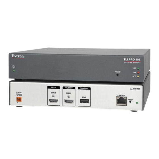
Page 12: Panel Features, Connections, And Setup
Panel Features, Connections, and Setup This section describes: TLI Pro 101 Rear Panel Features and Connections TLI Pro 101 Front Panel Features TLI Pro 101 Rear Panel Features and Connections TLI PRO 101 INPUT OUTPUT CONTROL LAN/PoE HDMI HDMI POWER 12 V 1.0A MAX RESET... - Page 13 Power (see figure 2 on page 5)— Connect the 2-pole, 3.5 mm captive screw connector from the provided 12 VDC power supply to the power supply socket on the rear panel. Figure 3 shows how to wire the connector. Ensure the connections have the correct polarity.
- Page 14 ATTENTION: • Always use a power supply provided by or specified by Extron. Use of an unauthorized power supply voids all regulatory compliance certification and may cause damage to the supply and the end product. • Utilisez toujours une source d’alimentation fournie ou recommandée par Extron. L’utilisation d’une source d’alimentation non autorisée annule toute conformité...
- Page 15 HDMI Input (see figure 2 on page 5) — Plug the cable from the input source device into this female HDMI type A connector. Secure the HDMI connector to the TLI Pro 101 with the provided LockIt HDMI lacing bracket (see the LockIt HDMI Lacing Bracket Installation Guide at www.extron.com).
- Page 16 Screen Resolutions Resolution 23.98 Hz 24 Hz 25 Hz 29.97 Hz 30 Hz 50 Hz 59.94 Hz 60 Hz 800x600 1024x768 1280x768 1280x800 1280x1024 1360x768 1366x768 1440x900 1400x1050 1600x900 1680x1050 1600x1200 1920x1200 720p 1080p 2048x1080 Custom 1 For new resolutions (field support only) USB Connector (see figure 2 on page 5) —...
- Page 17 Network and Power over Ethernet Connector (see figure 2 on page 5) — Connect the interface to the LAN using a twisted pair cable, terminated with an RJ-45 connector. Use a straight-through Ethernet cable to connect the panel to a switch or router.
- Page 18 ATTENTION: • The TLI Pro 101 is intended for connection to a Power over Ethernet circuit for intra-building use only and is considered to be part of a Network Environment 0 per IEC TR62101. • Le TLI Pro 101 est conçu pour une connexion à un circuit PoE pour une utilisation intérieure seulement et est considéré...
-
Page 19: Tli Pro 101 Front Panel Features
Reset mode LED (see figure 2 on page 5) — Provides feedback about the reset status when the reset button is pressed (see Reset Modes on page 27). Reset button (recessed) (see figure 2 on page 5) — Allows the unit to be reset in any of three different modes (see Reset Modes on page 27). -
Page 20: On-Screen Menus
On-screen Menus On-screen menus allow initial configuration of the TLI Pro 101. Setup Menu Calibration Screen Setup Menu To access the setup menus, press the recessed front-panel button (see figure 5, Menu The menu opens at the Status screen. There are six different screens (Status, Network, Output, Audio, Input, and Advanced) that can be selected by pressing the appropriate button in the navigation panel at the top of the screen. -
Page 21: Network
Network Verify with your network administrator whether the IP address for the TLI is assigned by Dynamic Host Configuration Protocol (DHCP) or set manually. If they are set manually, you need to obtain an IP address, a subnet mask, a gateway address, and a Domain Name Server (DNS) IP address from the network administrator. - Page 22 If DHCP is disabled, set the unit IP address, subnet mask, gateway address, and DNS server address. Press the button for the address to be edited. A screen opens, showing the address and a numerical keypad. Figure 9. Numeric Pad for Setting IP Addresses Press Clear to remove the old address.
-
Page 23: Output
Output Sets the Display Resolution, Sleep Timer, and Display Timer and enables a Test Pattern to be shown. Status Network Audio Input Advanced Output Exit Resolution Sleep Timer Display Timer Current Output: 1024x768 @ 60Hz Set Display Display Native 1280x1024 @ 60Hz min. - Page 24 Sleep timer The Sleep Timer determines how long the panel is inactive before it enters sleep mode, when the screen goes dark to save power. To deactivate the sleep timer, click . The controls for the Sleep Timer are grayed out. To set the sleep timer, ensure the function is activated by clicking Set the time (in minutes) by pressing the up and down arrows until the required time appears in the gray box.
-
Page 25: Audio
Audio Status Network Output Input Advanced Audio Exit Master Click Sound HDMI Figure 13. Audio Screen Use the slider control to adjust the Master, Click, Sound, and HDMI In settings. The slider adjusts the volume setting from 0 to 100% in 1% increments. By default all sliders are set to 80%. -
Page 26: Input
Input Status Network Output Audio Input Advanced Exit Input EDID Input Audio and Video Current Native: 1024x768 @ 60Hz Input Audio: Change Native To: Match Output HDCP 1080p @ 60Hz Authorize: Aspect Project Resolution Fill Follow Ratio: 1080p @ 60Hz Other Adjust Picture Resolutions... - Page 27 Input Audio and Video The two pairs of buttons on the right of the screen allow three Input Audio and Video settings to be toggled On and Off. — Enables 2CH PCM support on input EDID. Input Audio Input Audio: Input Audio is On by default.
-
Page 28: Advanced
Advanced The Advanced window provides additional information about the interface and the GUI Designer project that is uploaded to it. Status Network Output Audio Input Advanced Exit System GUI Project Touchpanel Name: TLI Pro 101 192.168.254.253 Room Name: Project2.gdl Resolution: 1920x1080 Controller Name: IPCP Pro 550 192.168.254.254 Creation Date:... -
Page 29: Callibration Screen
Calibration Screen Touch crosshair to calibrate 800 x 480 Figure 19. Touch Calibration Screen Press and hold down the recessed front-panel menu button (see figure 5, , on page 12) for at least 3 seconds. Release the button. The calibration screen opens to show cross-hairs (see figure 19, above). -
Page 30: Configuration Software
Configuration Software This section of the user guide provides information about: Configuration Software TLI Pro 101 Web Page Updating the Firmware Configuration Software Designing a graphical user interface (GUI) for the TouchLink panel takes two steps: Design the layout of the screen text and graphics using GUI Designer. Assign functions to the text and graphics using Global Configurator. -
Page 31: Tli Pro 101 Web Page
The single page provides general and network information about the unit. It also allows you to upgrade the unit firmware. Use the Setup Menu (see page 13) or the Toolbelt feature of Global Configurator to configure the network settings of the TLI Pro 101. Extron Electronics ® General Status Project Model Name: TLI Pro 101... -
Page 32: Updating The Firmware
Updating the Firmware Firmware for the TLI Pro 101 can be upgraded using the Toolbelt feature of Global Configurator or the TLI Pro 101 web page. Before starting, consult your IT team and ensure that the interface has a unique IP address. Downloading Firmware Using Extron Firmware Loader Power on a computer that is connected to the same network as the interface. -
Page 33: Mounting
Mounting This section outlines the various options for mounting the TLI Pro 101. Tabletop Placement Rack Mounting Under-desk Mounting Tabletop Placement Attach the four provided rubber feet to the bottom of the unit and place it in any convenient location. Rack Mounting Underwriters Laboratories Guidelines for Rack Mounting The following Underwriters Laboratories (UL) guidelines are relevant to the safe installation of these products in a rack:... -
Page 34: Reference Material
Reference Material This section describes: Reset Modes Licensed Third-Party Software Used in the Interface Reset Modes The TLI Pro 101 has three reset modes that are initiated by pressing the Reset button: Use Factory Firmware Reset All IP Settings Reset to Factory Defaults The Reset button is found on the rear panel (see figure on page 5). -
Page 35: Reset All Ip Settings
Purpose and Notes Use this mode to temporarily boot up the unit with factory installed firmware for a single power cycle in the event that a firmware update has failed or if incompatibility issues arise with user- loaded firmware. NOTE: User-defined web pages may not work correctly if you are using an earlier firmware version. -
Page 36: Licensed Third-Party Software Used In The Interface
Licensed Third-Party Software Used in the Interface TLI Pro 101 interfaces use various licensed third-party software packages during operation. To view details about third-party packages and associated licensing, click the internal Web page License Information button on the (see on page 24). To view a copy of a listed package license in the License Information window, click the link in the License column for the relevant package. - Page 37 Extron Electronics makes no further warranties either expressed or implied with respect to the product and its quality, performance, merchantability, or fitness for any particular use. In no event will Extron Electronics be liable for direct, indirect, or consequential damages resulting from any defect in this product even if Extron Electronics has been advised of such damage.
Need help?
Do you have a question about the TouchLink TLI Pro 101 and is the answer not in the manual?
Questions and answers