Extron electronics TouchLink TLI Pro 201 User Manual
Interface control systems
Hide thumbs
Also See for TouchLink TLI Pro 201:
- User manual (46 pages) ,
- Setup manual (4 pages) ,
- Setup manual (4 pages)

Related Manuals for Extron electronics TouchLink TLI Pro 201


Summary of Contents for Extron electronics TouchLink TLI Pro 201
- Page 1 User Guide TouchLink ® TLI Pro 201 TouchLink Pro Interface Control Systems 68-3514-01 Rev. A 08 20...
- Page 2 Safety Instructions Safety Instructions • English Istruzioni di sicurezza • Italiano AVVERTENZA: Il simbolo, , se usato sul prodotto, serve ad This symbol, , when used on the product, is intended to WARNING avvertire l’utente della presenza di tensione non isolata pericolosa alert the user of the presence of uninsulated dangerous voltage within the all’interno del contenitore del prodotto che può...
- Page 3 安全記事 • 繁體中文 안전 지침 • 한국어 警 告 경고: 이 기호 가 제품에 사용될 경우, 제품의 인클로저 내에 있는 若產品 上使 用此 符 號 , 是 為了提 醒 使 用者,產品 機 殼內 存 在 著 접지되지 않은 위험한 전류로 인해 사용자가 감전될 위험이 있음을 可能會導致觸電之風險的未絕緣危險電壓。...
- Page 4 FCC Class A Notice This equipment has been tested and found to comply with the limits for a Class A digital device, pursuant to part 15 of the FCC rules. The Class A limits provide reasonable protection against harmful interference when the equipment is operated in a commercial environment.
- Page 5 Conventions Used in this Guide In this user guide, the following are used: Notifications WARNING: Potential risk of severe injury or death. AVERTISSEMENT : Risque potentiel de blessure grave ou de mort. CAUTION: Risk of minor personal injury. ATTENTION : Risque de blessure mineure. ATTENTION: Risk of property damage.
-
Page 7: Table Of Contents
Contents Introduction Annotation ............28 ..........1 About the TLI Pro 201 ..........1 Annotation Overview ..........28 Features ...............1 Local Annotation ..........28 Application Diagram ..........2 Remote Annotation ........28 Differences between TLI Pro 201 Local and Remote Annotation ........29 Installation Overview ........3 Mounting ............30 Panel Features ..........5 Wall Mounting ............30... - Page 8 TLI Pro 201 • Contents viii...
-
Page 9: Introduction
Introduction This guide describes the function, installation, and operation of the TLI Pro 201. Unless otherwise stated, the terms “interface” and “TouchLink Pro interface” also refer to this model. This section provides an overview of the TLI Pro 201: About the TLI Pro 201 •... -
Page 10: Application Diagram
Uses the same HID device drivers as the Annotator 300 and TLI Pro 101 • Advanced Extron video signal processing with a high-performance scaling • engine Automatic clock synchronization — Allows touchpanel to display the accurate • time and date Adjustable sleep timer puts interface into sleep mode •... -
Page 11: Installation Overview
Installation Overview Before starting, download and install the latest versions of the following software: Toolbelt — Provides device discovery, device information, firmware updates, … and configuration of network settings, system utilities, and user management for TouchLink Pro interfaces. Global Configurator Professional and Global Configurator Plus — For …... - Page 12 Connect the Ethernet cable. The TLI Pro 201 must be powered by PoE+ (see LAN/PoE+ Port on page 6). ATTENTION: Do not connect the power supply before reading the Attention • page 8. Veuillez lire la partie « mises en garde »...
-
Page 13: Panel Features
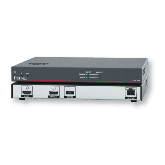
Panel Features This section describes: TLI Pro 201 Rear Panel Features and Connections • TLI Pro 201 Front Panel Features • TLI Pro 201 Rear Panel Features and Connections LAN/PoE + INPUT OUTPUT DEVICE A A A B B B C C C D D D Figure 2. - Page 14 TLI Pro 201 Output Screen Resolutions Resolution 23.98 Hz 24 Hz 25 Hz 29.97 Hz 30 Hz 50 Hz 59.94 Hz 60 Hz 640x480 800x600 1024x768 1280x768 1280x800 1280x1024 1360x768 1366x768 1440x900 1400x1050 1600x900 1680x1050 1600x1200 1920x540 1920x720 1920x1200 480p 576p 720p 1080p...
-
Page 15: Connecting Power
An Extron IPL Pro control processor must also be connected to the same network domain as the TLI Pro 201. See the www.extron.com for a list of suggested models. The network port has two LEDs. The green Link LED lights steadily to indicate that the TLI Pro 201 is connected correctly to a network. - Page 16 ATTENTION: The TLI Pro 201 is intended for connection to a Power over Ethernet circuit for • intra-building use only and is considered to be part of a Network Environment 0 per IEC TR62101. Le TLI Pro 201 est conçu pour une connexion à un circuit PoE pour une utilisation •...
- Page 17 Securing the HDMI Connector Use a HDMI cable to connect the HDMI input or output to the female HDMI ports on the front panel of the interface (figure , on page 5). Use the provided LockIt HDMI lacing bracket to secure the HDMI connector: Plug the HDMI cable into the panel connection.
-
Page 18: Tli Pro 201 Front Panel Features
TLI Pro 201 Front Panel Features INPUT OUTPUT SIGNAL MENU HDCP TLI Pro 201 A A A B B B C C C D D D Figure 5. TLI Pro 201 Plus Front Panel Power LED — Indicates the power status and the reset status of the unit. Reset button (recessed) —... -
Page 19: On-Screen Menus
On-screen Menus On-screen menus allow initial configuration of the TLI Pro 201. Setup Menu • Calibration Screen • Setup Menu Press the recessed front-panel Menu button (see figure 5, , on page 10) to access the on-screen setup menu. Press the button briefly (less than 3 seconds) to open the setup menu. Press the button briefly a second time to exit the setup menu. -
Page 20: Network
Network Verify with your network administrator whether the IP address for the TLI is assigned by Dynamic Host Configuration Protocol (DHCP) or set manually. If they are set manually, you need to obtain an IP Address, a Subnet Mask, a Gateway Address, and a Domain Name Server (DNS) IP address from the network administrator. - Page 21 If DHCP is off, set the unit IP Address, Subnet Mask, Gateway address, and DNS Primary address. Press the button for the address to be edited. A dialog box opens, showing the address and a numerical keypad. IP Address Clear 1 9 2 1 6 8 2 5 4...
-
Page 22: Output
Output Sets the display Resolution, Sleep Timer, and Display Timer and enables Test Patterns to be shown. Status Network Audio Input Advanced Output Exit Resolution Sleep Timer Display Timer Current Output: 1024x768 @ 60Hz Set Display Display Native 1280x1024 @ 60Hz min. - Page 23 Sleep Timer The Sleep Timer determines how long the panel is inactive before it enters sleep mode, when the screen goes dark to save power. To deactivate the sleep timer, click Off. The controls for the Sleep Timer are grayed out. To set the sleep timer, ensure the function is activated by clicking On.
-
Page 24: Audio
Audio Status Network Output Input Advanced Audio Exit Master Click Sound HDMI Figure 14. Audio Screen Use the fader control to adjust the Master, Click, Sound, and HDMI audio input settings. The fader adjusts the volume setting from 0 to 100% in 1% increments. By default all faders are set to 80%. -
Page 25: Input
Input Status Network Output Audio Input Advanced Exit Connected Display: 1024x768 @ 60 Hz, HDMI, LPCM-2Ch Output Config: 1080p @ 60 Hz, HDMI, LPCM-2Ch Input Status Signal: 1024x768 @ 60 Hz HDMI LPCM-2Ch HDMI EDID: 1080p @ 60 Hz HDMI LPCM-2Ch Input Configuration Aspect... - Page 26 EDID Minder — Opens the EDID Minder dialog box: EDID Minder - HDMI Match EDID to Connected Display: 1080p @ 60 Hz, HDMI, LPCM-2Ch Match EDID to Output Config: 1080p @ 60 Hz, HDMI, LPCM-2Ch Resolution Refresh Rate (Hz) 1600x900 1400x1050 59.94 1680x1050...
-
Page 27: Advanced
Image Settings — Opens the Image Settings dialog box: No Signal Brightness Default Contrast Detail Overscan Exit Figure 17. Image Settings Dialog Box The panel at the top of the screen shows the current image settings. The buttons underneath allow the image to be configured: Brightness —... -
Page 28: Calibration Screen
Menu PIN (see figure 18 on page 19) — To prevent unauthorized access to the setup menu users can set a PIN, which is a 4-digit number. Each digit can have any value from 0-9. The PIN setup options allow you to enable, disable, or change the setup menu PIN. Click On or Change to open the Enter New Menu PIN dialog box. - Page 29 Touch the crosshair. Once the touch is detected, a box appears around the crosshair. Touch center of crosshair to calibrate Bottom Bottom Left Left Right Right Figure 21. Calibration Screen: Touch Detected When the crosshair is released, the calibration process moves to the next screen. Touch center of crosshair to calibrate Bottom Bottom...
-
Page 30: Configuration Software
Configuration Software This section of the user guide provides information about: Configuration Software • Downloading Software • Using the Software • TLI Pro 201 Web Page • Updating the Firmware • Configuration Software NOTES: The TLI Pro 201 uses GUI Designer and Global Configurator Plus and •... - Page 31 1 1 1 2 2 2 3 3 3 3 3 3 4 4 4 Figure 24. Downloading Software You may see the product immediately, for example Global Configurator Plus and Professional (see figure 24, ). You may need to use the left and right arrows ( ) to scroll through all the highlighted products.
-
Page 32: Using The Software
Using the Software Designing a graphical user interface (GUI) for the TouchLink panel takes two steps: Design the layout of the screen text and graphics using GUI Designer. Assign functions to the text and graphics using Global Configurator. GUI Designer — Use the GUI Designer software to design the screen layout for the third-party touchpanel connected to the TLI Pro 201. -
Page 33: Tli Pro 201 Web Page
TLI Pro 201 Web Page To access the TLI Pro 201 default web page, enter the IP address of the unit into the web browser of a PC connected to the same subnet. The login page opens. Enter your user name and password. Figure 25. -
Page 34: Updating The Firmware
Updating the Firmware Firmware for the TLI Pro 201 can be upgraded using Toolbelt or the TLI Pro 201 web page. Before starting, consult your IT team and ensure that the interface has a unique IP address. Downloading Firmware Firmware must be downloaded to a PC on the same network as the TLI Pro 201. On the Extron Website, click Download ( Click Firmware ( Figure 27. - Page 35 The Download Firmware page opens: Figure 28. Selecting Firmware to Download. Click the letter T from the list of letters ( Scroll down the page until you find the firmware for the TLI Pro 201. NOTE: Your product appears in this list only if a new version of the firmware has been released since the product was was first introduced.
-
Page 36: Annotation
Annotation Annotation Overview If desired, use GUI Designer to create a graphical annotation toolbar for the TLI Pro 201 (see the GUI Designer Help File). This allows allows a presenter to draw, write, or point in real-time over live video and graphics presentations. Figure 29. -
Page 37: Differences Between Tli Pro 201 Local And Remote Annotation
Differences between TLI Pro 201 Local and Remote Annotation Annotation Features TLI Pro 201 TLI Pro 201 with Annotator 300 (Local Annotation) (Remote Annotation) Toolbar GUI Designer Embedded OSD Drop shadow Always On On/Off Date/time stamp GUI Designer Annotation auto clear GCP/GS Input or Freq change Video outputs... -
Page 38: Mounting
Mounting This section outlines the various options for mounting the TLI Pro 201. Wall Mounting • Rack Mounting • Other Mounting Options • Wall Mounting The compact design of the TLI Pro 201 allows discreet installation within a lectern or to the wall behind a flat panel display. See www.extron.com for a list of appropriate kits and follow the instructions included with the kit. -
Page 39: Reference Material
Reference Material This section describes: Network Port Requirements and Licensed Third-Party Software • Reset Modes • Secure Sockets Layer (SSL) Certificates • IEEE 802.1X Certificates • Network Port Requirements and Licensed Third-Party Software For information about network port requirements and licensed third-party software for the touchpanels described in this guide, please refer to the Pro Series Control Product Network Ports and Licenses Guide, which is available at www.extron.com. -
Page 40: Use Factory Firmware
Use Factory Firmware Purpose and Notes Use this mode to temporarily boot up the unit with factory installed firmware for a single power cycle in the event that a firmware update has failed or if incompatibility issues arise with user-loaded firmware. Activation To start the Use Factory Firmware reset mode and replace firmware: Remove power to the TLI Pro 201. -
Page 41: Reset To Factory Defaults
Reset to Factory Defaults Purpose and Notes Reset to Factory Defaults mode is useful if you want to start over with configuration and uploading. Activation To reset the unit to all factory default settings: Hold down the Reset button for about 9 seconds until the Power LED blinks three times (once at 3 seconds, again at 6 seconds, and again at 9 seconds). -
Page 42: Secure Sockets Layer (Ssl) Certificates
Secure Sockets Layer (SSL) Certificates Extron TouchLink Pro control systems ship with factory-installed SSL certificates created by Extron. If you want or are required to use a different SSL certificate at your installation site, then you can use system utilities in the Toolbelt software to change the SSL certificate at any time. -
Page 43: Certificate File Requirements
Certificate File Requirements PEM (Privacy-enhanced Electronic Mail) file types are ASCII encoded, and they are the required format for 802.1X authentication for the TouchLink Pro control systems. DER (Distinguished Encoding Rules) file types are binary encoded and can typically have several file extension variations, such as .crt and .cer. - Page 44 Extron Electronics makes no further warranties either expressed or implied with respect to the product and its quality, performance, merchantability, or fitness for any particular use. In no event will Extron be liable for direct, indirect, or consequential damages resulting from any defect in this product even if Extron has been advised of such damage.
Need help?
Do you have a question about the TouchLink TLI Pro 201 and is the answer not in the manual?
Questions and answers