Extron electronics TouchLink TLI Pro 201 User Manual
Hide thumbs
Also See for TouchLink TLI Pro 201:
- User manual (44 pages) ,
- Setup manual (4 pages) ,
- Setup manual (4 pages)

Related Manuals for Extron electronics TouchLink TLI Pro 201


Summary of Contents for Extron electronics TouchLink TLI Pro 201
- Page 1 User Guide TouchLink ® TLI Pro 201 TouchLink Pro Interface Control Systems 68-3514-01 Rev. C 10 21...
- Page 2 Safety Instructions Safety Instructions • English Instructions de sécurité • Français AVERTISSEMENT : Ce pictogramme, , lorsqu’il est utilisé sur le WARNING: This symbol, , when used on the product, is intended to produit, signale à l’utilisateur la présence à l’intérieur du boîtier du alert the user of the presence of uninsulated dangerous voltage within produit d’une tension électrique dangereuse susceptible de provoquer the product’s enclosure that may present a risk of electric shock.
- Page 3 安全说明 • 简体中文 警告: 产品上的这个标志意在警告用户, 该产品机壳内有暴露的危险 电压, 有触电危险。 注意: 产品上的这个标志意在提示用户, 设备随附的用户手册中有重 要的操作和维护(维修)说明。 关于我们产品的安全指南、遵循的规范、EMI/EMF 的兼容性、无障碍使 用的特性等相关内容, 敬请访问 Extron 网站 , www.extron.com,参见 Extron 安全规范指南,产品编号 (www.extron.com) 。 68-290-01 安全記事 • 繁體中文 안전 지침 • 한국어 경고: 이 기호 가 제품에 사용될 경우, 제품의 인클로저 내에 있는 警告: 若產品上使用此符號,...
- Page 4 FCC Class A Notice This equipment has been tested and found to comply with the limits for a Class A digital device, pursuant to part 15 of the FCC rules. The Class A limits provide reasonable protection against harmful interference when the equipment is operated in a commercial environment.
- Page 5 Conventions Used in this Guide In this user guide, the following are used: Notifications WARNING: Potential risk of severe injury or death. AVERTISSEMENT : Risque potentiel de blessure grave ou de mort. CAUTION: Risk of minor personal injury. ATTENTION : Risque de blessure mineure. ATTENTION: Risk of property damage.
-
Page 7: Table Of Contents
Contents Introduction Configuration Software .......23 ..........1 About the TLI Pro 201 ..........1 Configuration Software ........23 Features ...............1 Downloading Software ........23 Application Diagram ..........2 Using the Software ..........25 TLI Pro 201 Web Page ........26 Updating the Firmware ........28 Installation Overview ........3 Downloading Firmware ........28 Mounting ............30... - Page 8 TLI Pro 201 • Contents viii...
-
Page 9: Introduction
Introduction This guide describes the function, installation, and operation of the TLI Pro 201. Unless otherwise stated, the terms “interface” and “TouchLink Pro interface” also refer to this model. This section provides an overview of the TLI Pro 201: About the TLI Pro 201 •... -
Page 10: Application Diagram
Application Diagram Extron TLI Pro 201 AV LAN 4K TouchLink Interface Ethernet/PoE+ Ethernet INPUT OUTPUT DEVICE LAN/PoE+ HDMI Ethernet HDMI Science Science Building Building 4K 3rd Party Touchscreen en n Ethernet Extron REMOTE POWER RS-232 DA2 HD 4K Plus --A MAX INPUT OUTPUTS Tx Rx G... -
Page 11: Installation Overview
Installation Overview Before starting, download and install the latest versions of the following software: Toolbelt — Provides device discovery, device information, firmware updates, … and configuration of network settings, system utilities, and user management for TouchLink Pro interfaces. Global Configurator Professional and Global Configurator Plus — For …... - Page 12 Connect the Ethernet cable. The TLI Pro 201 must be powered by PoE+ (see LAN/PoE+ Port on page 6). ATTENTION: Do not connect the power supply before reading the Attention • page 8. Veuillez lire la partie « mises en garde »...
-
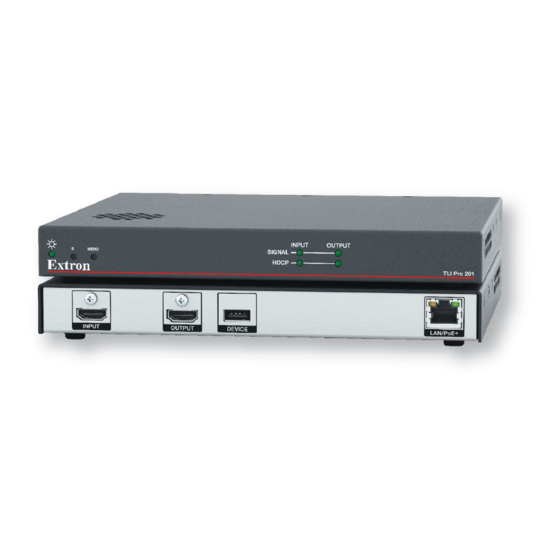
Page 13: Panel Features
Panel Features This section describes: TLI Pro 201 Rear Panel Features and Connections • TLI Pro 201 Front Panel Features • TLI Pro 201 Rear Panel Features and Connections LAN/PoE + INPUT OUTPUT DEVICE A A A B B B C C C D D D Figure 2. - Page 14 TLI Pro 201 Output Screen Resolutions Resolution 23.98 Hz 24 Hz 25 Hz 29.97 Hz 30 Hz 50 Hz 59.94 Hz 60 Hz 640x480 800x600 1024x768 1280x768 1280x800 1280x1024 1360x768 1366x768 1440x900 1400x1050 1600x900 1680x1050 1600x1200 1920x540 1920x720 1920x1200 480p 576p 720p 1080p...
-
Page 15: Connecting Power
An Extron IPL Pro Series or IPL Pro xi Series control processor must also be connected to the same network domain as the TLI Pro 201. See the www.extron.com for a list of suggested models. The network port has two LEDs. The green Link LED lights steadily to indicate that the TLI Pro 201 is connected correctly to a network. - Page 16 ATTENTION: The TLI Pro 201 is intended for connection to a Power over Ethernet Plus circuit for • intra-building use only and is considered to be part of a Network Environment 0 per IEC TR62101. Le TLI Pro 201 est conçu pour une connexion à un circuit PoE+ pour une utilisation •...
-
Page 17: Securing The Hdmi Connector
Securing the HDMI Connector Use a HDMI cable to connect the HDMI input or output to the HDMI ports on the front panel of the interface (figure , on page 5). Use the provided LockIt HDMI lacing bracket to secure the HDMI connector: Plug the HDMI cable into the panel connection. -
Page 18: Hid Modules
HID Modules For the TLI Pro 201 to work with your touchscreen display, you must have the correct embedded HID module loaded onto the TLI Pro 201. The TLI Pro 201 comes with a large range of HID modules already loaded. Connect your touch display to the TLI Pro 201 to see if it will work with one of the existing modules. -
Page 19: On-Screen Menus
On-screen Menus On-screen menus allow initial configuration of the TLI Pro 201. Setup Menu • Calibration Screen • Setup Menu Press the recessed front-panel Menu button (see figure 5, , on page 10) to access the on-screen setup menu. Press the button briefly (less than 3 seconds) to open the setup menu. Press the button briefly a second time to exit the setup menu. -
Page 20: Network
Network Verify with your network administrator whether the IP address for the TLI is assigned by Dynamic Host Configuration Protocol (DHCP) or set manually. If they are set manually, you need to obtain an IP Address, a Subnet Mask, a Gateway Address, and a Domain Name Server (DNS) IP address from the network administrator. - Page 21 If DHCP is off, set the unit IP Address, Subnet Mask, Gateway address, and DNS Primary address. The MAC Address cannot be editied. Press the button for the address to be edited. A dialog box opens, showing the address and a numerical keypad. IP Address 192.168.254.251 SUBMIT...
-
Page 22: Output
Output Sets the display Resolution, Sleep Timer, and Display Timer and enables Test Patterns to be shown. Touchpanel Setup EXIT Output STATUS Resolution Sleep Timer NETWORK Current Output 1080p at 30Hz Set Display OUTPUT Minutes Display Native 3840x2160 at 30Hz INPUT Display Timer Project Resolution... - Page 23 Sleep Timer The Sleep Timer determines how long the panel is inactive before it enters sleep mode (see Notes below). To deactivate the sleep timer, set the switch to Off. While the sleep timer is deactivated, the controls for the sleep timer are unavailable. To activate the sleep timer, set the switch to On.
-
Page 24: Input
Input Touchpanel Setup Touchpanel Setup EXIT EXIT Input Input STATUS STATUS Connected Display Output Config NETWORK NETWORK 3840x2160 at 30Hz 1080p at 30Hz HDMI HDMI LPCM 2Ch LPCM 2Ch OUTPUT OUTPUT INPUT INPUT Input Status Input Configuration AUDIO AUDIO 1080p at 60Hz Aspect Ratio FILL FOLLOW... - Page 25 EDID Minder — Opens the EDID Minder dialog box: Edid Minder Connected Display Output Config 3840x2160 @ 30Hz 1080p @ 30Hz HDMI CAPTURE HDMI LPCM 2Ch LPCM 2Ch Resolution Match EDID to Source Refresh Rate 1080p @ 30Hz 23.98 3840x2160 Match EDID to Display 1920x540 3840x2160 @ 30Hz...
-
Page 26: Audio
Video Preview — Opens the Video Preview window: Video Preview No Signal Figure 16. Video Preview Window The window provides a preview of the source connected to the HDMI Input (see figure , on page 5). Audio Touchpanel Setup EXIT Audio STATUS System... -
Page 27: Project Information
Project Information Touchpanel Setup EXIT Project Information STATUS System Information NETWORK Touchpanel Name: TLI Pro 201 :192.168.254.251 Controller Name: IPCP Pro 255 : 192.168.254.250 OUTPUT Controller IP: 192.168.254.250 INPUT Global Configurator Project Name: GCPro Project.gcpro AUDIO Version: 0.0.1.0 Creation Date: 4/15/2021 1:37:00 PM PROJECT INFORMATION Revision Date:... - Page 28 Menu PIN — To prevent unauthorized access to the setup menu, users can set a 4-digit PIN. Each digit can have any value from 0-9. The PIN setup options allow you to enable, disable, or change the setup menu PIN. To disable the PIN, set the Menu Pin switch to Off.
-
Page 29: Calibration Screen
Calibration Screen Press and hold down the recessed front-panel Menu button (see figure 5, , on page 10) for at least 3 seconds. Touch center of crosshair to calibrate Bottom Bottom Left Left Right Right Figure 21. Calibration Screen Opens The calibration screen opens to show cross-hairs in the top left corner (see figure 21). - Page 30 When the crosshair is released, the calibration process moves to the next screen. Touch center of crosshair to calibrate Bottom Bottom Left Right Right Left Figure 23. Calibration Screen: Calibrate the Next Crosshair The top left crosshair disappears. • The top right crosshair appears. •...
-
Page 31: Configuration Software
Configuration Software This section of the user guide provides information about: Configuration Software • Downloading Software • Using the Software • TLI Pro 201 Web Page • Updating the Firmware • Configuration Software NOTES: The TLI Pro 201 uses GUI Designer and Global Configurator Plus and •... - Page 32 1 1 1 2 2 2 3 3 3 3 3 3 4 4 4 Figure 25. Downloading Software You may see the product immediately, for example Global Configurator Plus and Professional (see figure 25, ). You may need to use the left and right arrows ( ) to scroll through all the highlighted products.
-
Page 33: Using The Software
Using the Software Designing a graphical user interface (GUI) for the TouchLink panel takes two steps: Design the layout of the screen text and graphics using GUI Designer. Assign functions to the text and graphics using Global Configurator. GUI Designer — Use the GUI Designer software to design the screen layout for the third-party touchpanel connected to the TLI Pro 201. -
Page 34: Tli Pro 201 Web Page
TLI Pro 201 Web Page To access the TLI Pro 201 default web page, enter the IP address of the unit into the web browser of a PC connected to the same subnet. The login page opens. Enter your user name and password. Figure 26. - Page 35 The single page provides general and network information about the unit. This information is read-only. Use the Setup Menu (see page 11) or Toolbelt to configure the network settings of the TLI Pro 201. Figure 27. TLI Pro 201 Web Page TLI Pro 201 •...
-
Page 36: Updating The Firmware
Updating the Firmware Firmware for the TLI Pro 201 can be upgraded using Toolbelt. Before starting, consult your IT team and ensure that the interface has a unique IP address. Downloading Firmware Firmware must be downloaded to a PC on the same network as the TLI Pro 201. On the Extron Website, click Download ( Click Firmware ( Figure 28. - Page 37 (Optional) Click Release Notes (see figure ), on the previous page) for more information about the firmware. Click Download ( Follow the on-screen instructions to download the program. An executable file is downloaded to the PC. Go to the Downloads folder and click on the file to install the firmware on the PC. By default, it is stored at C:\\Program Files (x86)\Extron\Firmware\<product name>\<firmware version>.
-
Page 38: Mounting
Mounting This section outlines the various options for mounting the TLI Pro 201. Wall Mounting • Rack Mounting • Other Mounting Options • Wall Mounting The compact design of the TLI Pro 201 allows discreet installation within a lectern or to the wall behind a flat panel display. See www.extron.com for a list of appropriate kits and follow the instructions included with the kit. -
Page 39: Consignes Ul Pour Le Montage En Rack
Consignes UL pour le montage en rack Les consignes UL (« Underwriters Laboratories ») suivantes concernent l’installation en rack d’un boîtier TLI Pro 201 : CAUTION : Température ambiante élevée — En cas d’installation de l’équipement dans • un rack fermé ou composé de plusieurs unités, la température du rack peut être supérieure à... -
Page 40: Reference Material
Reference Material This section describes: Best Practices for Cleaning Your Extron Products • Network Port Requirements and Licensed Third-Party Software • Reset Modes • Secure Sockets Layer (SSL) Certificates • IEEE 802.1X Certificates • SNMP • Best Practices for Cleaning Your Extron Products Depending on the device, application, and location, there may be times when it... -
Page 41: Network Port Requirements And Licensed Third-Party Software
Network Port Requirements and Licensed Third-Party Software For information about network port requirements and licensed third-party software for the touchpanels described in this guide, please refer to the Extron Control Product Network Ports and Licenses Guide, which is available at www.extron.com. Reset Modes The TLI Pro 201 has three reset modes that are initiated by pressing the Reset button: Use Factory Firmware... -
Page 42: Reset All Ip Settings
Reset All IP Settings Purpose and Notes Reset All IP Settings mode enables you to reset IP settings to factory defaults. Activation To reset all IP settings: Hold down the reset button for about 6 seconds until the Power LED blinks twice (once at 3 seconds and again at 6 seconds). -
Page 43: Enable Or Disable The Dhcp Client
Enable or Disable the DHCP Client This mode toggles between DHCP enabled and DHCP disabled. This can also be carried Network screen of Network out from the screen of the Setup menu (see page 12) or the www.extron.com Toolbelt (see the Toolbelt Help File at Activation To enable or disable the DHCP client for the LAN port: Press the reset button five times (consecutively). -
Page 44: Ieee 802.1X Certificates
IEEE 802.1X Certificates IEEE 802.1X is a standard that enables port-based network access control via an authentication server. The protocol requires that all devices must be authenticated before gaining privileges to access the secure part of the network. The Extron implementation of 802.1X supports PEAP - MSCHAPV2 and EAP - TLS methods of authentication. -
Page 45: Private Key File Requirements
Private Key File Requirements Private key files are required only when employing machine certificates. Follow these requirements for creating a private key: Its file name consists of the following types of valid characters: • Alphanumerical (A-Z, a-z, 0-9) characters • Some special characters (colon [:], underscore [_], and hyphen [-]) •... - Page 46 Extron Warranty Extron warrants this product against defects in materials and workmanship for a period of three years from the date of purchase. In the event of malfunction during the warranty period attributable directly to faulty workmanship and/ or materials, Extron will, at its option, repair or replace said products or components, to whatever extent it shall deem necessary to restore said product to proper operating condition, provided that it is returned within the warranty period, with proof of purchase and description of malfunction to: USA, Canada, South America,...
Need help?
Do you have a question about the TouchLink TLI Pro 201 and is the answer not in the manual?
Questions and answers