
Related Manuals for Extron electronics IPL EXP I/O Series


Summary of Contents for Extron electronics IPL EXP I/O Series
- Page 1 IPL EXP I/O Series Control System Expansion Interfaces User Guide IP Link Pro xi Products ® 68-3490-01, Rev. D 09 24...
-
Page 2: Safety Instructions
Safety Instructions Safety Instructions • English Instructions de sécurité • Français AVERTISSEMENT : Ce pictogramme, , lorsqu’il est utilisé sur le WARNING: This symbol, , when used on the product, is intended to produit, signale à l’utilisateur la présence à l’intérieur du boîtier du produit alert the user of the presence of uninsulated dangerous voltage within the d’une tension électrique dangereuse susceptible de provoquer un choc product’s enclosure that may present a risk of electric shock. - Page 3 • 安全说明 简体中文 警告: 产品上的这个标志意在警告用户, 该产品机壳内有暴露的危险 电压, 有触电危险。 注意: 产品上的这个标志意在提示用户, 设备随附的用户手册中有重 要的操作和维护(维修)说明。 关于我们产品的安全指南、遵循的规范、EMI/EMF 的兼容性、无障碍使 用的特性等相关内容, 敬请访问 Extron 网站 , www.extron.com,参见 Extron 安全规范指南,产品编 号 68-290-01 。 安全記事 • 繁體中文 안전 지침 • 한국어 경고: 이 기호 가 제품에 사용될 경우, 제품의 인클로저 내에 있는 警告: 若產品上使用此符號,...
-
Page 4: Fcc Class A Notice
FCC Class A Notice This equipment has been tested and found to comply with the limits for a Class A digital device, pursuant to part 15 of the FCC rules. The Class A limits provide reasonable protection against harmful interference when the equipment is operated in a commercial environment. -
Page 5: Software Commands
Conventions Used in this Guide Notifications The following notifications are used in this guide: CAUTION: Risk of minor personal injury. ATTENTION : Risque de blessure mineure. ATTENTION: • Risk of property damage. • Risque de dommages matériels. NOTE: A note draws attention to important information. TIP: A tip provides a suggestion to make working with the application easier. -
Page 7: Table Of Contents
Before You Begin ...............................1 What This Guide Covers ..........................1 Conventions Used in This Guide ........................1 Important Information You Need Before Installation ..................1 About the IPL EXP I/O Series ..........................2 Features .................................3 Feature Summary Table ..........................3 Application Diagram ............................4 Device Control ..............................4 About Global Configurator ..........................5... - Page 8 Private Key File Requirements ........................38 SNMP ................................38 Firmware Updates ..........................39 Determining the Firmware Version ........................39 Using Toolbelt Software ..........................39 Using a Browser ............................39 Updating the Firmware ............................39 Locating and Downloading the Firmware .....................40 Installing Firmware ............................40 IPL EXP I/O Series • Contents viii...
-
Page 9: Introduction
Conventions Used in This Guide • Throughout this guide the IPL EXP I/O Series products are also referred to as the “IPL EXP,” “EXP,” or “expansion interface.” • IPCP Pro Q xi and xi Series control processors are also referred to as the “IPCP,” “IPCP Pro Q xi,”... -
Page 10: About The Ipl Exp I/O Series
About the IPL EXP I/O Series The Extron IPL EXP I/O Series control system expansion interfaces make it possible to easily expand the number and variety of ports available in an Extron IP Link Pro xi control system. These expansion interfaces work in conjunction with IPCP Pro xi Series control processors. -
Page 11: Features
The following table provides a summary of models and major features. Features Ports Model Plastic — — — — — IPL EXP S2 Plastic — — — — — IPL EXP S5 Plastic — — IPL EXP 200 Metal — — IPL EXP RIO8 IPL EXP I/O Series • Introduction... -
Page 12: Application Diagram
See the Global Configurator Help File (which comes with the software) or the help files for Global Scripter or the ControlScript Deployment Utility for details on setting up the IPL EXP and the IPCP and for downloading, programming, or configuring device control commands. IPL EXP I/O Series • Introduction... -
Page 13: About Global Configurator
PC hardware and software system requirements are listed in the description section. In some cases, minimum device firmware version requirements are also listed there. • If system requirements are not listed on the software package web page, contact an Extron support representative. IPL EXP I/O Series • Introduction... -
Page 14: Hardware Features And Installation
Write down the MAC address of each network interface on each IP Link Pro device to be used. • Obtain model names and setup information for devices the system will control. IPL EXP I/O Series • Hardware Features and Installation... -
Page 15: Mount And Cable All Devices
Add Network Button Panels (NBPs) and set them up. Assign button functions as desired. • Add the IPL EXP expansion interfaces and configure their ports. • Set up monitors, schedules, macros, and local variables. IPL EXP I/O Series • Hardware Features and Installation... -
Page 16: Test And Troubleshoot
• Test the system (see the Troubleshooting section starting on page 34 for an outline of items to check during system troubleshooting). • Make adjustments to wiring or configuration as needed. IPL EXP I/O Series • Hardware Features and Installation... -
Page 17: Network Communication Setup
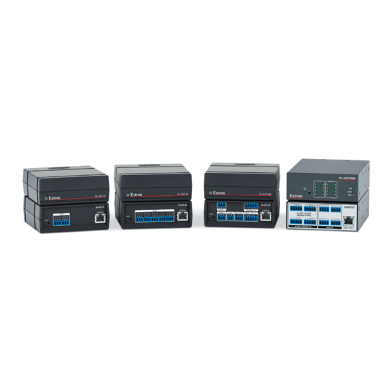
IPL EXP S5 Power Reset Digital Relay LAN/ Button LEDs Network LEDs LEDs (recessed) Figure 4. Front Panels — Left: IPL EXP S2, IPL EXP S5 Right: IPL EXP 200, IPL EXP RIO8 IPL EXP I/O Series • Hardware Features and Installation... -
Page 18: Rear Panel Features
UL rack mounting guidelines below for safe installation. Then securely mount the control system Ports, Addressing, and expansion interface and other devices and attach cables using the wiring section (see Connections on page 14) as a wiring guide. IPL EXP I/O Series • Hardware Features and Installation... -
Page 19: Ul Rack Mounting Guidelines
UL Rack Mounting Guidelines The following Underwriters Laboratories (UL) guidelines pertain to the safe installation of IPL EXP I/O Series expansion interfaces in a rack. CAUTION: Elevated operating ambient temperature — If installed in a closed or multi-unit rack assembly, the •... -
Page 20: Rack Mounting
EXP and through the tie wrap anchor points on the ZipClip, then around the cables. b. Connect and pull the tie wraps until they are secure. Do not over-tighten. Tie Wrap IPL EXP I/O Series • Hardware Features and Installation... -
Page 21: Furniture Mounting
2. Insert the EXP into the ZipClip as described previously and press to snap it into place. Under a Desk IPL EXP 200 IPL EXP I/O Series • Hardware Features and Installation... -
Page 22: Ports, Addressing, And Connections
IPL EXP expansion interface. • The rest of the IPL EXP I/O Series expansion interfaces (IPL EXP 200, IPL EXP S5, IPL EXP S2) accept power over Ethernet (PoE) or PoE+ through the LAN port in addition to network communication. - Page 23 • See the Global Configurator Help File for details on the Limit and Over conditions. 6) on the next page. See the wiring diagrams (figure IPL EXP I/O Series • Hardware Features and Installation...
- Page 24 24 VDC Ceiling Extron OCS 100C Occupancy Sensor ECM S10 Tx Extron ECM S10 Rx Partition closed Receiver does not detect signal from transmitter. Figure 6. Wiring the DC Power Output Ports IPL EXP I/O Series • Hardware Features and Installation...
-
Page 25: Bidirectional Control And Communication Connections And Features
Maximum distances between the EXP and the device being controlled are generally up to 200 feet (61 m) but can vary based on factors such as cable gauge, baud rates, environment, and output levels from the EXP and the device being controlled. IPL EXP I/O Series • Hardware Features and Installation... - Page 26 The factory configured passwords for this device have been set to the device serial number. Passwords are case sensitive. Performing a Reset to Factory Defaults reset (see Resetting the Unit on page 27) sets the extron password to IPL EXP I/O Series • Hardware Features and Installation...
- Page 27 Address MAC: 00-05-A6-XX-XX-XX A label that indicates the MAC address is located on the rear or side panel of each S/N: ####### E###### EXP unit. IPL EXP I/O Series • Hardware Features and Installation...
-
Page 28: Unidirectional Control And Communication Connections
One Single IR Emitter Dual IR Emitter Installing Two Single Emitters When installing only single emitters, tie them in series as shown below. Ground (−) (−) IR Signal (+) (−) Two Single IR Emitters IPL EXP I/O Series • Hardware Features and Installation... - Page 29 NOTE: The pulse function is absolute: it always sets the relay state to closed, times out (briefly), then opens the contact. It overrides the previously selected setting (on state, off state, or toggle). IPL EXP I/O Series • Hardware Features and Installation...
-
Page 30: Additional Control Ports
2.8 VDC — port off, logic high There is also an internal, selectable, pull-up resistor connected to +5 VDC, which you can use if the connected device does not provide its own power. IPL EXP I/O Series • Hardware Features and Installation... - Page 31 Two-position Switch With Pull-up Two-position switch is open: logic high, front panel LED (IPL EXP RIO8 only) is off. Two-position switch is closed: logic low, front panel LED (IPL EXP RIO8 only) is lit. IPL EXP I/O Series • Hardware Features and Installation...
- Page 32 If the pull-up resistor is disabled, voltage output is determined by an external source device. • If the pull-up resistor is enabled, switch 2 is closed, voltage output is 4.3 VDC. Each I/O port is capable of accepting 250 mA, maximum. IPL EXP I/O Series • Hardware Features and Installation...
- Page 33 The connected LED is off when the port and switch 1 are open. The connected LED is on when the port and switch 1 are closed. IPL EXP I/O Series • Hardware Features and Installation...
- Page 34 1k ohms DTP T UWP 232 D SW 2 Digital Voltage SW 1 Protection Figure 15. Digital I/O Digital Output Application With Pull-up: Contact Closure Input Selection on a Connected Device IPL EXP I/O Series • Hardware Features and Installation...
-
Page 35: Resetting The Unit
9 seconds; the third set of blinks indicating the last mode. The modes are separate functions, not a continuation from one mode to the next. IPL EXP I/O Series Expansion Interface Reset Mode Summary Use This... - Page 36 IPL EXP I/O Series Expansion Interface Reset Mode Summary Use This Activation Result Mode to... Reset IP To reset all network settings: Reset All Network Settings mode: settings and 1. Press and hold the Reset button until the Reset or Power Turns DHCP off.
-
Page 37: Software-Based Configuration And Control
The default web pages embedded within the expansion interface provide a means to view general hardware information, network settings, and, if configured, project information. You cannot configure the expansion interface via the embedded web pages. IPL EXP I/O Series • Software-based Configuration and Control... -
Page 38: Basic Setup Steps: A Guide To This Section And Other Resources
Import GUI layouts and con gure the touchpanels or other interfaces. Save the project. Build and upload the con guration to the control processor. Test the system, make adjustments, nalize con guration. Figure 16. Overall Configuration Steps IPL EXP I/O Series • Software-based Configuration and Control... -
Page 39: Downloading The Software And Getting Started
Select the correct result from the drop-down list, if needed. A link opens to allow you to download the software or firmware. IPL EXP I/O Series • Software-based Configuration and Control... -
Page 40: Obtaining Control Drivers
IP Link Pro drivers. They do not support serial that were created for IP Link (non-Pro) products. However, existing Extron IR driver files are supported. If the system requires a driver that is not already available, you can request a new serial (RS-232) or Ethernet driver from Extron. IPL EXP I/O Series • Software-based Configuration and Control... -
Page 41: Things To Do After Installing Gc And Before Starting A Project
Using GC: Helpful Tips Resources and notes • The IPL EXP I/O Series Setup Guide is shipped with the unit. It includes a quick reference to the front and rear panel features, and covers basic hardware installation. Front Panel Features Ports, Addressing, and Connections •... -
Page 42: Troubleshooting
3. If contact is established with the unit, but the IPL EXP web pages cannot be accessed by your browser program, verify (via an Internet network options or preferences menu) that your browser is configured for direct network connection and is not set up to use a proxy server. IPL EXP I/O Series • Software-based Configuration and Control... -
Page 43: Device Control Connections And Configuration
Verify that input current at any digital input or output port does not exceed 250 mA. If you are still experiencing problems, call the Extron Sales & Technical Support Hotline or the Extron S3 Control Systems Support Hotline (1.800.633.9877). IPL EXP I/O Series • Software-based Configuration and Control... -
Page 44: Reference Information
.gdl — This is a GUI Designer layout created for TouchLink Pro a touchpanel or third-party touch interface. • .glta — This is a GUI layout template. • .gs – This is a Global Scripter project file. IPL EXP I/O Series • Reference Information... -
Page 45: Secure Sockets Layer (Ssl) Certificates
The 802.1X Primer white paper, also available from www.extron.com, provides a general overview of the • protocol and its use within a control system. NOTES: • You must run Toolbelt as an administrator. • Machine certificates require a private key file, which can be encrypted. IPL EXP I/O Series • Reference Information... -
Page 46: Certificate File Requirements
Extron control products support the following security levels: • Management Information Base 2 (MIB-II) • SNMPv2c IPL EXP I/O Series • Reference Information... -
Page 47: Firmware Updates
6, the Software-Based Configuration and Control section starting on page 29, and the IPL EXP I/O Series Setup Guide. Using Toolbelt Software 1. Open the Toolbelt software. 2. Either add the desired expansion interface manually or start device discovery and select the desired IPL EXP from the list of discovered devices. -
Page 48: Locating And Downloading The Firmware
PC. Therefore, to continue using the web page or Toolbelt you need to refresh the web page or reconnect via Toolbelt after the firmware update. IPL EXP I/O Series • Firmware Updates... -
Page 49: Extron Warranty
Electronics makes no further warranties either expressed or implied with respect to the product and its quality, performance, merchantability, or fitness for any particular use. In no event will Extron Electronics be liable for direct, indirect, or consequential damages resulting from any defect in this product even if Extron Electronics has been advised of such damage.
Need help?
Do you have a question about the IPL EXP I/O Series and is the answer not in the manual?
Questions and answers