Table of Contents
Advertisement
1
PRINTING
at
JULY 2018
Sega Amusements International Limited.
42 Barwell Business Park, Leatherhead Road, Chessington, Surrey, KT9 2NY. United Kingdom.
Telephone: +44 (0) 208 391 8090
Facsimile:
+44 (0) 208 391 8099
mailbox@sega.co.uk
segaarcade.com
Sega Games Co,. Ltd.
1-2-12, Haneda, Ota-ku, Tokyo, 144-8531. Japan.
Telephone: +81-3-5736-7111
Facsimile:
+81-3-6871-7672
sega-games.co.jp
© SEGA
Errors and omissions excepted (E&OE)
IMPORTANT
• Before using this product, read this manual carefully to understand the
contents herein stated.
• After reading this manual, be sure to keep it near the product or in a
convenient place for easy reference when necessary.
Advertisement
Table of Contents

Related Manuals for Sega Daytona Championship USA


Summary of Contents for Sega Daytona Championship USA
- Page 1 PRINTING JULY 2018 Sega Amusements International Limited. 42 Barwell Business Park, Leatherhead Road, Chessington, Surrey, KT9 2NY. United Kingdom. Telephone: +44 (0) 208 391 8090 Facsimile: +44 (0) 208 391 8099 mailbox@sega.co.uk segaarcade.com Sega Games Co,. Ltd. 1-2-12, Haneda, Ota-ku, Tokyo, 144-8531. Japan.
-
Page 2: Introduction
This manual is intended to provide detailed descriptions together with all necessary information covering the general operation of electronic assemblies, electromechanical, servicing control, spare parts, etc. for the product, "DAYTONA CHAMPIONSHIP USA”. This manual is intended for the owners and personnel managers in charge of operation of this product. - Page 3 Definition of 'Site Maintenance Personnel or Other Qualified Individuals Servicing and maintenance work of the contents herein stated should be performed by the SERVICEMAN stipulated as per IEC Standard. Those who do not have technical expertise and knowledge other than the SERVICEMAN are not allowed to perform the work herein stated.
- Page 4 The symbol shown below will be placed on all products manufactured from 13th August 2005, which indicates this product must NOT be disposed of with other normal waste. Upon purchasing any EEE from SEGA Amusements International Ltd. The user accepts responsibility to dispose of their waste equipment by arranging to return it to a designated UK collection point (AATF) or an Approved Exporter (AE) for the correct recycling of waste electrical and electronic equipment.
- Page 5 BEFORE USING THE PRODUCT , BE SURE TO READ THE FOLLOWING: To maintain safety: To ensure the safe operation of this product, be sure to read the following before usage: The following instructions are intended for the users, operators and the personnel in charge of the operation of the product.
- Page 6 INSPECTIONS IMMEDIATELY AFTER TRANSPORTING THE PRODUCT TO THE LOCATION Normally, at the time of shipment, SEGA products are in a status allowing for usage immediately after transporting to the location. Nevertheless, an irregular situation may occur during transportation. Before turning on the power, check the following points to ensure that the product has been transported in a satisfactory status.
-
Page 7: Table Of Contents
TABLE OF CONTENTS INTRODUCTION HANDLING PRECAUTIONS PRECAUTIONS REGARDING INSTALLATION LOCATION 2-1 LIMITATIONS OF USAGE 2-2 OPERATION AREA 2-3 OPERATION AREA - MULTIPLE CABINETS PRECAUTIONS REGARDING PRODUCT OPERATION 3-1 BEFORE OPERATION 3-2 DURING OPERATION (PAYING ATTENTION TO CUSTOMERS) PARTS DESCRIPTION ACCESSORIES ASSEMBLY AND INSTALLATION 6-1 UNPACKING THE CABINETS 6-2 JOINING THE CABINETS... - Page 8 COIN HANDLING 12-1 CLEANING THE COIN SELECTOR 12-2 FAULT FINDING 12-3 ADJUSTING THE PRICE OF PLAY (EXCEL) 12-4 ADJUSTING THE PRICE COMMON (USA) LAMPS AND LIGHTING 13-1 COIN DOOR LAMP 13-2 START/VIEW BUTTON PANEL 13-3 FOOTWELL LIGHTING 13-4 INNER PANEL LIGHTING 13-5 SEAT RING LIGHTING 13-6 BILLBOARD LIGHTING 13-7 UNDER SEAT LIGHTING...
-
Page 9: Handling Precautions
● To avoid an electric shock or short circuit, do not plug in or unplug quickly. ● To avoid an electric shock, do not plug in or unplug with a wet hand. ● Do not expose power cords or earth wires on the surface, (floor, passage, etc.). If exposed, the power cords and earth wires are susceptible to damage. Dam- aged cords and wires can cause an electric shock or short circuit. ● To avoid causing a fire or an electric shock, do not put things on or damage the power cords. ● During/after installing the product, do not unnecessarily pull the power cord. If damaged, the power cord can cause a fire or an electric shock. ● In case the power cord is damaged, ask for a replacement through where the product was purchased from or the office herein stated. Using the cord as is damaged can cause fire, an electric shock or leakage. ● Be sure to perform grounding appropriately. Inappropriate grounding can cause an electric shock. ● Be sure to use fuses meeting the specified rating. Using fuses exceeding the specified rating can cause a fire or an electric shock. ● Be sure that connections such as IC BD are made properly. Insufficient insertion can cause an electric shock. ● Specification changes, removal of equipment, conversion and/or addition, not designated by SEGA are not permitted. - Failure to observe this may cause a fire or an electric shock. Non-compliance with this instruction can have a bad influence upon physical conditions of the players or the onlookers, or result in injury during play. - SEGA shall not be held responsible for damage, compensation for damage to a third party, caused by specification changes not designated by SEGA. ● Do not perform any work or change parts not listed in this manual. Doing so may lead to an accident. If you need to perform any work not listed in this manual, request work from the office indicated in this manual or the point of purchase, or inquires for details. ● Be sure to perform periodic maintenance inspections herein stated. - Page 10 CONCERNING THE STICKER DISPLAY This SEGA product has stickers attached describing the product manufacture No. (Serial No.) and Electrical Specifications. It also has a Sticker describing where to contact for repair and for purchasing parts. When inquiring about or asking for repairs, mention the Serial No. and Name of Machine indicated on the Sticker.
- Page 11 CAUTION & WARNING LABEL LOCATIONS...
-
Page 12: Precautions Regarding Installation Location
PRECAUTIONS REGARDING INSTALLATION LOCATION This product is an indoor game machine. Do not install it outside. Even indoors, avoid installing in places mentioned below so as not to cause a fire, electric shock, injury and/or malfunction: - Places subject to rain, water leakage, or places subject to high humidity in the proximity of an indoor swimming pool and/or shower, etc. - Places subject to direct sunlight, or places subject to high temperatures in the proximity of heating units, etc. - Places filled with inflammable gas or vicinity of highly inflammable/volatile chemicals or hazardous matter. - Dusty places/areas. - Sloped surfaces. - Places subject to any type of violent impact. - Vicinity of anti-disaster facilities such as fire exits and fire extinguishers. - The operating (ambient) temperature range is not from 5°C to 30°C. - Places near water or spray from water such as a jet wash or swimming pool. -
Page 13: Limitations Of Usage
2-1 LIMITATIONS OF USAGE ● Be sure to check the Electrical Specifications. Ensure that this product is compatible with the location’s power supply, voltage, and frequency requirements. A plate describing Electrical Specifications is attached to the product. Non-compliance with the Electrical Specifications can cause a fire and electric shock. ● This product requires a breaker and earth mechanism as part of the location facilities. Using the product without these can cause a fire and electric shock. ● Ensure that the indoor wiring for the power supply is rated at 15 A or higher (AC single phase 100 V ~ 120 V area), and 7 A or higher (AC 220 V ~ 240 V area). Non-compliance with the Electrical Specifications can cause a fire and electric shock. ● Be sure that the ring main has a rating of 32A (AC220V ~ 240V area). ● Be sure to use an independent power supply equipped with an earth leakage breaker. Using a power supply without an earth leakage breaker can cause an outbreak of fire if a power surge occurs. ● Putting many loads on one electrical outlet can cause generation of heat and a fire resulting from overload. ● When using an extension cord, ensure that the cord is rated at 15 A or higher (AC 100 V ~ 120 V area) and 7 A or higher (AC 220 V ~ 240 V area). Using a cord rated lower than the specified rating can cause a fire and electric shock. -
Page 14: Operation Area
2-2 OPERATION AREA ● For the operation of a single machine, secure a minimum area of 2.1m (82.6in) (W) x 2.3m (90.5in) (D). If the machine rolls during play it could lead to serious injury. You must secure an area equal to or greater than the space specified in this document. ● Be sure to provide sufficient space specified in this manual. Do not allow objects to block the ventilation ports. Doing so can cause generation of heat and fire. ● SEGA shall not be held responsible for damage or compensation for damage to a third party, resulting from the failure to observe this instruction. ● If the machine does not fit through the entryway to the installation location, do not disassemble it without first consulting the instructions. If the machine still does not fit through the entryway after following the procedures in this manual, contact your retailer or the office listed in this manual. To install this product, the entrance must be at least 1.07 m in width and 1.5 m in height. Secure an area of no less than 2.1m (82.6in) x 2.3m (90.5in) for operation, taking into consideration the safety of the players and spectators of this game. 2-2 fig. 01... -
Page 15: Operation Area - Multiple Cabinets
2-3 OPERATION AREA - MULTIPLE CABINETS Secure an area of no less than 3.3m (129in) x 2.3m (90.5in) for operation of the TWIN cabinet, taking into consideration the safety of the players and spectators of this game. To install this product, the entrance must be at least 1.05 m in width and 1.5m in height. When installing multiple cabinets, make sure the rules are followed below. Keep a distance of no greater than 5mm (3/16in) between each Monitor Cabinet. Keep a distance of a minimum of 0.5m either side of the end cabinets. Keep a minimum distance of 0.15m at the rear of the cabinet for ventilation. - Page 16 Eight cabinet formation. 2.3m (90.5in) 2-2 fig. 04...
-
Page 17: Precautions Regarding Product Operation
PRECAUTIONS REGARDING PRODUCT OPERATION To avoid injury and trouble, be sure to pay attention to the behavior of visitors and players. 3-1 BEFORE OPERATION In order to avoid accidents, check the following before starting the operation: ● To ensure maximum safety for the players and customers, ensure that where the product is operated has sufficient lighting to allow any warnings to be read. Operation under insufficient lighting can cause bodily contact with each other, hitting accidents, and/or trouble between customers. ● Be sure to perform appropriate adjustment of the monitor. For operation of this machine, do not leave monitor flickering or deviation as is. Failure to observe this can have a bad influence upon the players’ or customers’ physical conditions. ● It is suggested to ensure a space allowing the players who feel sick while playing the game to take a rest. ● Check if all of the adjusters are in contact with the surface. If they are not, the Cabinet can move and cause potential accidents. 15CM 03-1 fig. - Page 18 ● Do not put any heavy item(s) on this product. Placing any heavy item on the product can cause falling accidents or parts damage. ● Do not climb on the product. Climbing on the product can cause falling accidents. To check the top portion of the product, use a step ladder. ● When using a stepladder or stool while working, do not hold onto the billboard by any electrical components. Holding the billboard in these areas may cause damage, electronic component failure or personal safety issues. ● To avoid electric shock, check to see if door & cover parts are damaged or omitted. ● To avoid electric shock, short circuit and/or parts damage, do not put the following items on or in the periphery of the product: - Flower vases, flowerpots, cups, water tanks, cosmetics, and receptacles/ containers/vessels containing chemicals or water ● To avoid injury, be sure to provide sufficient space by considering the crowd situation at the installation location. Insufficient installation space can cause customers to bump into each other and could cause injury. ● Every day when cleaning the Controller (Steering Wheel), inspect the hoop and buttons, making sure that there are no scratches or cracks in the surface, and that the fastening screws are not loose. If the game is played with scratches, cracks, or loose screws, it can cause injuries to the player or to people nearby. Ensure that there are no loose fixings Clean the controller daily Ensure that there are no loose fixings 03-1 fig.
- Page 19 DURING OPERATION (PATRON CONDUCT) To avoid injury and unacceptable behavior, be sure to constantly give careful attention to the behavior and manner of the spectators and players alike. To avoid injury and accidents, those who fall under the following categories are not allowed to play the game: • Those who need assistance such as the use of an apparatus when walking.
-
Page 20: During Operation (Paying Attention To Customers)
3-2 DURING OPERATION (PAYING ATTENTION TO CUSTOMERS) To avoid injury and trouble, be sure to pay attention to the behavior of visitors and players. ● For safety reasons, do not allow any of the following people to play the game: - Those who require supporting devices (or the like) to walk. - Those who have high blood pressure or a heart problem. - Those who have experienced muscle convulsion or loss of consciousness when playing video games, etc. - Page 21 ● Immediately stop such violent acts such as hitting and kicking the product. Such violent acts can cause parts damage or falling down, resulting in injury due to fragments. ● Two or more players must never be allowed to play using a single Control Unit. Playing in such a way could lead to physical injuries. ● Players should be warned not to place personal effects or other objects on the base of the machine. If the safety sensor fails to detect these items, the motion of the machine may cause them to fly out and strike other patrons. ● Players should be instructed to adjust the seat by moving it forward or backward to fit their body size before playing the game. Playing the game in an unnatural position can lead to unforeseen accidents. ● Persons other than the player should not be allowed to touch the controls during play. They may brush against or collide with the controls or the player, possibly resulting in accidents.
-
Page 22: Parts Description
PARTS DESCRIPTION Camera Control Panel Main Display Display Cabi 04 fig. 01 Seat Cabi Coin Tower Head Rest Seat Seat Back 04 fig. 02 Main door CPU Compartment Mains SW 04 fig. 03... -
Page 23: Accessories
ACCESSORIES Confirm that the accessories listed on this page are present when setting up the product. Accessories marked “Spare” in the note column are consumable items but included as spares. OWNER’S and SEVICE MANUAL STICKER SHEET C EPILEPSY MULTI 420-0028-05UK (1) 440-CS0186UKUK (1) This manual Multilingual caution label - epilepsy seizure... - Page 24 The parts listed in Table 5b are needed to finalise the installation. These are traditionally parts that are applied by the customer at location. Please take a moment to check the contents. If for some reason some the parts are not present, call your local office along with the machine serial number to arrange for the relevant parts to be sent to you (PLEASE NOTE THAT SOME ITEMS ARE ALREADY FITTED TO LOCATION TO AID INSTALL) 204 207...
-
Page 25: Assembly And Installation
ASSEMBLY AND INSTALLATION ● Perform assembly work by following the procedure herein stated. Failure to comply with the instructions can cause electric shock. ● Perform assembling as per this manual. Since this is a complex machine, incorrect assembling can cause an electric shock, machine damage and/or improper functioning as per specified performance. ● When assembling, more than one person is required. Depending on the assembly work, there are some cases in which working by one person alone can cause personal injury or parts damage. ● Ensure that connectors are properly connected. Improper connections can cause electric shock. ● Be careful not to damage any wires. Damaged wires may cause electric shock or short circuit or present a risk of fire. ● This work should be carried out by site maintenance personnel or other qualified professionals. Work performed by non-technical personnel can cause a severe accident such as electric shock. Failing to comply with this instruction can cause a severe accident such as electric shock to the player during operation. If no one with proper technological expertise is available, request service from the office indicated in this document or the point of purchase so as to ensure safety. ● Provide sufficient space so that assembling can be performed. Performing work in places with narrow space or low ceiling may cause an accident and assembly work to be difficult. ● To perform work safely and avoid serious accident such as the cabinet falling down, do not perform work in places where step-like grade differences, a ditch, or slope exist. ● Do not leave power cords or ground wires exposed in areas of heavy foot traffic. Doing so may cause them to become damaged, possibly resulting in electric shock and/or short circuits. When laying wiring across the floor, always use safety covers to protect the wires (wiring diameter: power cable - approx. φ 8). - Page 26 ● Handle molded parts with care. Excessive weight or pressure may cause them to break and the broken pieces may cause injury. ● To perform the operation safely and accurately, use a safe, steady footstool or stepladder. Working without this may lead to a fall and possible injury. ● Attempting to forcefully connect the incorrect connector or connecting a connector at the wrong angle or facing may damage the connector and could lead to overheating and burn related injuries. ● When attaching or removing doors or lids, be careful that your hand or finger does not get caught in anything. ● Be very careful when handling LCD screen. The screen can be damaged easily and cannot be repaired once damaged. Such damage can only be repaired by completely replacing the screen. ● Be careful not to damage parts surfaces. In some cases, if such surfaces are damaged, the part must be replaced; it cannot be reinforced or repaired. The assembly of this product is performed in the following 6 steps: UNPACKING THE CABINET JOINING THE CABINETS INSTALLING THE BILLBOARD INSTALLING MULTIPLE CABINETS (COMMUNICATION) LINKING THE CABINETS (COMMUNICATION) APPLYING POWER...
- Page 27 Tools Required for Assembly Operation - Philips screwdriver (for M4, M6 screws) - Hex Drive for (M4, M6 & M8 screws) Locking Step Ladders - - A torch or any additional lighting 24mm 100Mb Network Switch (Required for linking 3 or more cabs. - A wrench or 24mm Spanner.
-
Page 28: Unpacking The Cabinets
6-1 UNPACKING THE CABINETS ● Be very careful when removing the Monitor and Seat cabinets from the pallet. Use only hydraulic lifting equipment such as a fork lift. Some parts weigh in excess of 200Kgs. DO NOT attempt to remove the machine from the pallet by hand. Doing so may result in serious personal injury and/or damage to the cabinet and its components. - Page 29 Seat Cabinet The ASSY SEAT CABI are packed as pairs along with the INSTALLATION KIT. Like the DISPLAY CABI, the ASSY SEAT CABI’s are attached to the pallet by means of a strong clear bag which is shrunk down to fit the contents within. Using a blade or scissors, carefully cut away the bag, from around the top edge of the pallet, taking care not to damage its contents.
-
Page 30: Joining The Cabinets
6-2 JOINING THE CABINETS It is important that a suitable location is secured to enable installation to be carried out safely. Please refer the beginning of this manual for Operational Area. Making sure that the castors come into contact with the floor, carefully place and align both front and rear cabinets into position. - Page 31 Carefully push the ASSY SEAT CABI up towards the ASSY MONITOR CABI, taking care not to trap any harnesses. 6-3 fig. 03 6-3 fig. 04 Once the SEAT CAB and MONITOR CAB are together, secure them using (4) M8 fixings in the positions illustrated below.
- Page 32 Secure the BRACKET JOINT INNER on the inside of the cabinets on both sides with (4) M4X25 fixings. 6-2 fig. 06 BRKT JOINT INNER Secure the FOOTWELL LID from the Installation Kit with (4) M4X25 fixings. M4 FIXINGS 6-2 fig. 07 Secure the FOOTWELL LID SASH from the Installation Kit with (3) M4X25 fixings. M4 FIXINGS 6-2 fig.
-
Page 33: Installing The Billboard
6-3 INSTALLING THE BILLBOARD Attach the BILLBOARD MOUNT BRKTS using (2) M6X25 fixings on each bracket. 6-3 fig. 01 M6 FIXINGS Mount the ASSY BILLBOARD by inserting the BRKT BILLBOARD over the BILLBOARD MOUNT BRKT. BRKT BILLBOARD 6-3 fig. 02... - Page 34 Secure the BILLBOARD in place using (2) M6X25 fixings on each bracket. 6-3 fig. 03 M6 FIXINGS Secure the BILLBOARD BUMPER in place by inserting either the left or right side, then gently bending the bumper into position on the opposite side. Secure with (2) M4x50 fixings (1 on each side). M4 FIXINGS 6-3 fig.
-
Page 35: Installing Multiple Cabinets
6-4 INSTALLING MULTIPLE CABINETS It is important that a suitable location is secured to enable installation to be carried out safely. Please refer the beginning of this manual for Operational Area. For this exercise we will show the procedures for installing (2) cabinets. This will reflect the procedures for installing 4, 6 or 8 cabinets. -
Page 36: Linking The Cabinets (Communication)
Note: The provided LAN cable will connect two cabinets only. To connect 3 or more cabinets, a network switch and multiple LAN cables are required. A network switch is not included in the installation kit but can be purchased through Sega on request. When powering the machine on for the first time, be sure NOT to have the network cables connected. Having the network cables connected when powering up for... -
Page 37: Applying Power
COMMUNICATION PORTS When connecting two or more cabinets AC Bracket Car 3 Car 1 Car 2 Network Switch 6-5 fig. 02 Car 1 Car 2 Car 3 6-5 fig. 03 6-6 APPLYING POWER Each cabinet has it own dedicated mains power input. Only use the power leads supplied with this machine. DO NOT connect more than 2 units in any one extension power lead. Using power leads not supplied with this product may cause on overload situation resulting in overheating, power failure or possibly fire hazard. • Use the power supply equipped with an earth leakage breaker. Use of power supply without such a breaker could result in fire if there is a current leakage. - Page 38 • Proceed with checks and tasks as indicated in these instructions. If instructions are not followed, or if tasks and/or checks are neglected, an electric shock or other very serious accident, even fatal accident, can occur. Also, customers could be injured while operating the product. • For safe operation, inspect and check the operation of each part of the product when turning on the power. If any defects are found, deal with them immediately. Never operate the product with defects still present.
- Page 39 Turn the main switch, located on the rear of the cockpit ON. This sends power throughout the product. Following the order below, output locations will activate. 1) WINDOWS/SEGA logo is displayed on LCD screen. 2) Steering Wheel calibrates - moves fully left/right then returns to the centre position. 3) Inter- cabinet communication check (in case of communication connection setting).
-
Page 40: Precautions When Moving
PRECAUTIONS WHEN MOVING ● As used in these instructions, the term “moving” refers to moving of the product within the same building, store or facility. These instructions do not cover moving between different buildings, areas, stores or facilities, since diverse factors are involved, not only packaging but also loading onto transport vehicles and securing the product in place during transport. -
Page 41: Moving The Machine
7-1 MOVING THE MACHINE ● Always disconnect the power cable before moving the product. If it is moved with the power cable connected, the cable could be damaged, causing fire or electric shock. ● To move the unit over the floor, pull in the adjustors and have the casters contact the floor. - Page 42 ● If you need to move components through a narrow or low door and the only way to get the separated components through is to turn them on their side (or if a separation method other than those described in this manual is required), either make a request to the office listed in this document or the place of pur- chase to perform the operation or contact them regarding how to perform it.
-
Page 43: Game Description
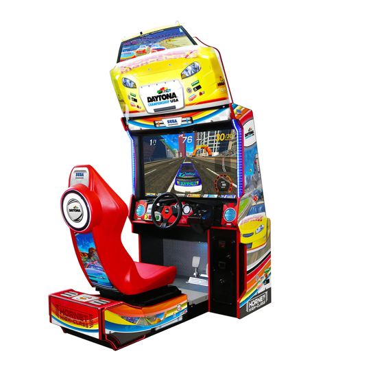
Daytona Championship USA is the latest racing game from legendary arcade machine manufacturer Sega Amusements. Daytona Championship USA is a reimagining of the classic arcade racing hit, Daytona USA. This new release contains 6 action packed tracks; 3 brand new courses accompanied by 3 beautifully redesigned classic tracks from the original game. - Page 44 Single Player If the player inserts a credit when a cabinet is not linked to any other machines (or if no other players join the lobby) and then presses the Start button, they will be taken in to a Single Player game where they are given the option between QUICK RACE, CHAMPIONSHIP* and TOURNAMENT* (*if enabled in the Game Settings of the Test &...
- Page 45 Standard Quick Race On the transmission screen, the player will be able to choose from standard quick race against AI players or compete in time lap mode. Quick Race is the default race type. To select time lap mode, the player must hold the start button and press down on the accelerator pedal when selecting transmission type (this is also detailed on the screen itself).
- Page 46 Time Lap Mode Time Lap mode is available in Single Player only. In this mode, only the player will be racing around the track, competing to set the fastest possible lap time. The player must reach checkpoints to extend the timer. If the player does not reach a checkpoint in time, the race will end.
- Page 47 The player turns the steering wheel left and right to highlight a letter and selects their choice by pressing down on the accelerator. During this time, a countdown timer will appear in the top right hand corner. If no name is selected before the timer reaches zero or if the START button is pressed, the game will generate a three letter name for the player.
- Page 48 Tournament Tournament is a specific mode that allows the operator to create a time limited event that will run between 1 and 30 days. During the selected time period, players compete for the fastest time on a track determined by the operator in the test menu.
- Page 49 Transmission/Car Select After selecting a track, the player will be prompted to select either automatic or manual transmission. Automatic is recommended for new players. In this transmission, the player will not be required to change gears as it will be done for them. Manual transmission is recommended for more experienced players.
- Page 50 Multiplayer Multiplayer Track Select After all players have entered the lobby, the track select screen will be shown allowing players to vote on what track they wish to race on. The track with the most votes will be selected. During this time, a countdown timer will appear in the top right hand corner. If no track is selected before the timer reaches zero, the track that is currently highlighted by the player will be chosen automatically.
- Page 51 HUD (Heads up Display) The image below represents the standard HUD screen in a single player race. It displays: 1 - LAP NUMBER Indicates the current lap the player is on and how many laps the race is in total 2 - LAP TIME COUNTER Indicates the current lap time as well as any previous lap times...
- Page 52 Single Player Time Lap HUD The Time Lap mode HUD contains all the elements of the standard HUD with some other included features: 1 - COURSE RECORD TIME This displays the current record time for a single lap. There are separate record times for Automatic and Manual transmissions 2 - TOTAL RECORD TIME This displays the player’s current best time for the...
- Page 53 Player Views Players can select from one of four views. These views can be selected by pressing the different view buttons on the cabinet. The views are labelled and shown below: View 1 View 2 View 3 View 4...
-
Page 54: Explanation Of Test And Data Display
EXPLANATION OF TEST AND DATA DISPLAY Perform tests and data checks periodically by manipulating the TEST Button and SERVICE Button in the cabinet. Follow the instructions in this chapter to conduct checks when the game machine is first installed, when money is being collected, or when the game machine does not operate properly. -
Page 55: Switch Unit
9-1 SWITCH UNIT Never touch places other than those specified. Touching places not specified can cause electric shock and short circuit accidents. Adjust the sound to the optimum volume, taking into consideration the environmental requirements of the installation location. Removing the Coin Meter circuitry renders the game inoperable. SWITCH UNIT Open the service panel and the switch unit shown will appear. -
Page 56: Test Mode
9-2 TEST MODE • The details of changes to Test Mode settings are saved when you exit from Test Mode by selecting EXIT from the System Test Mode Menu. If power is turned off before that point, changes to the settings will be lost. •... - Page 57 When changing the game configuration within the TEST MODE, be sure to exit • all screens in the correct manner by choosing exit. DO NOT turn the machine ON/OFF to resume game. Changes WILL NOT take effect unless the correct method is used.
- Page 58 Inputs Select ‘Input Test’ from the Test Menu to display the Input Test menu. This test is used to test system inputs such as steering wheels, pedals and switches. To implement the test, press each device that is listed and check the results on screen. 9-2 fig.
- Page 59 Outputs Select ‘OUTPUT TEST’ from the Game Test menu to display the Output Test Menu. This test is used to test system outputs such as lamps or actuators. Press the SERVICE button to move the cursor to the desired test item. Press the TEST button to test the selected item.
- Page 60 Calibration Select ‘Calibration Test’ from the Test Menu screen to display the Calibration Test menu. This test is used to calibrate analogue inputs and to test and set steering force feedback. Use the SERVICE button to move the cursor to the desired test item. Press the TEST button to enter the selected item. 9-2 fig.
- Page 61 Coin Settings This part of the test menu is used to set credit related parameters. Select COIN from the Test menu to display the Coin Settings Menu. Use the SERVICE button to move the cursor to the desired test item. Press the TEST button to enter the selected item.
- Page 62 Sound Settings This test is used to set audio levels for the game and to test function of the speaker system. Select ‘Sound Settings’ from the test menu to display the Sound Settings Menu. Use the SERVICE button to move the cursor to the desired test item. Press the TEST button to enter the selected item.
- Page 63 Screen This test is used to test the game display is working correctly. Use the SERVICE button to move the cursor to the desired test item. Press the TEST button to enter the selected item. 9-2 fig. 08 Colour Bars: Brightness: Selecting this will display the following screen.
- Page 64 Network Test This test is used to test the network link between cabinets (if connected). Select ‘NETWORK’ from the Test menu to display the Network Test Menu. IMPORTANT NOTES: In any cabinet configuration one cabinet must be set to ID=1, this is the Server that will control the network operation.
- Page 65 Bookkeeping – Screen 1 This test is used to review statistical data from the system. It consists of 7 screens of data. Screen 1 contains an overview of game play data. Select ‘BOOKKEEPING’ from the Test menu to display the Bookkeeping Test Menu. 9-2 fig.
- Page 66 Bookkeeping – Screen 2 This page displays cumulative individual modes and total plays. This is from the last point in time that the Bookkeeping was cleared. 9-2 fig. 14 TOTAL PLAYS: The total number of games played SINGLE PLAYER PLAYS: The total number of single player games MULTIPLAYER PLAYS: The total number of multiplayer games...
- Page 67 Bookkeeping – Screen 3 This page displays total game time and average game times for single and multiplayer modes. This is a cumulative total from the last point in time that Bookkeeping was cleared. All times are displayed in the format HHHH:MM:SS 9-2 fig.
- Page 68 Bookkeeping – Screen 4 This page displays a breakdown of the games on individual days. This is a cumulative total from the last point in time that the bookkeeping was cleared. 9-2 fig. 16 PLAYS ON SUNDAY: Cumulative count of plays for this day PLAYS ON MONDAY: Cumulative count of plays for this day PLAYS ON TUESDAY:...
- Page 69 Bookkeeping – Screen 5 This page displays a breakdown of the games into individual hours. This is a cumulative total from the last point in time that the bookkeeping was cleared. 9-2 fig. 17 PLAYS XX-XX: Cumulative count of plays during the specified hour NEXT PAGE: Proceed to bookkeeping screen #6 BACK TO MENU :...
- Page 70 Bookkeeping – Screen 6 This page displays a breakdown of the races into individual tracks. This is a cumulative total from the last point in time that the bookkeeping was cleared. 9-2 fig. 18 TRACK #1 -6: Cumulative count of plays on the specified track NEXT PAGE: Proceed to bookkeeping screen #7 BACK TO MENU:...
- Page 71 Bookkeeping – Screen 7 This page displays a breakdown of the different cars used in all game modes. This is a cumulative total from the last point in time that the bookkeeping was cleared. 0-2 fig. 19 CAR #1 -5: Cumulative count of plays using the specified car NEXT PAGE: Proceed to bookkeeping screen #1...
- Page 72 Clock Setting This test is used to set the current time and date of the computer system. Select ‘CLOCK’ from the Test Menu to enter the Clock Setting screen. When selected, the screen will show fields for YEAR, MONTH, DATE, HOURS, MINUTES and SECONDS.
- Page 73 Game Settings 1 This allows game parameters to be viewed and changed. Select GAME SETTINGS from the Test Menu screen to enter the Game Settings screen. If more than one cabinet is linked then game settings must be made from Cabinet 1 (Player 1) Test & Service Menu CABINET 2-8 IN LINKED GAME 9-2 fig 26 Limited options can be changed when a linked cabinet that is not ID=1...
- Page 74 Single Player/Cabinet 1 in Linked Game 9-2 fig 27 DIFFICULTY: Set the game difficulty (V EASY/EASY*/MEDIUM/HARD/V HARD) GAME LENGTH: Set the game length (V SHORT/SHORT/MEDIUM*/LONG/V LONG) CAMERA ENABLED: Use the player camera in game (YES*/NO) INSTANT REMATCH: Offer instant rematch after multiplayer game (ON*/OFF) START ON COIN ENTRY: Game starts as soon as credit is available (YES/NO*) MENU TIMINGS:...
- Page 75 Game Settings (Advanced) This page allows for advanced game parameters to be viewed and changed. Select GAME SETTINGS from the Test Menu screen to enter the Game Settings screen. From there highlight NEXT PAGE and push the TEST button to reached the GAME SETTINGS (ADVANCED) screen.
- Page 76 Tournament Set Up Tournament allows an operator to set up a time limited single player event. This can be customised and records are stored in a unique “Tournament” high score table. Once the time has elapsed the high score table will still be displayed but no further record can be set.
-
Page 77: Video Display
VIDEO DISPLAY The LCD display screen is adjusted prior to leaving the factory. Avoid any unnecessary adjustment. ● If the adjustment method in this manual does not resolve the problem, contact the customer service number in this manual or your supplier. ● Do not stick tape, stickers, or anything else onto the screen. Any kind of adhesive may damage the surface of the screen. 10-1 GENERAL DESCRIPTION This specification applies to the 46.0 inch Color TFT-LCD Module P460HVN02.0. This LCD module has a TFT active matrix type liquid crystal panel 1920x1080 pixels, and diagonal size of 46.0 inch. -
Page 78: Cleaning The Screen
10-2 CLEANING THE SCREEN ● Since the LCD display screen is susceptible to damage, pay careful attention to its handling. When cleaning, refrain from using water or volatile chemicals. ● Do not climb onto the control panel as this could lead to injuries. ● When reaching across the control panel to clean the screen, there is a risk of hurting your shoulder or arm. Use a mop with a non-feathery, soft, dry cloth mop head and wipe the surface of the screen. When the screen surface becomes dirty with dust, etc., clean it by using a soft cloth such as gauze. When water, and volatile chemicals such as benzene, thinner, etc., spill on the screen surface, it may be subject to damage, therefore, do not use them. -
Page 79: Adjustment Method
10-3 ADJUSTMENT METHOD All adjustment values are set accurately at the time of shipping from the factory. Do not adjust these values needlessly or apply adjustments not specified in this manual. The display may not appear properly if the values are incorrect. - Page 80 Button Names and Functions 10-3 Fig. 04 MENU: Turn the Picture Menu display ON and OFF. SELECT: Gains entry to the Item selected in the menu. (Highlights in Yellow when selected) Exits the Item adustment. Any changes made during this operation are actioned. DOWN: Moves the cursor (Black Bar) down to select a menu item.
- Page 81 On-Screen Display (OSD) Press the MENU Button while the OSD is not displayed to bring up the Picture Menu. On the Picture Menu, it is possible to perform various screen adjustments. 10-3 Fig. 05 Use the UP and DOWN Buttons to move the ‘Black Bar’to the item you want to adjust. After selecting the desired item, pressing the SELECT Button will extend the MENU Screen and allow adjustments to be changed.
- Page 82 On-Screen Display (OSD) <continued> 10-3 Fig. 07 Available Settings (Selects Operation Mode)) Selection availble - 6500K - 9300K - USER BRIGHTNESS (Adjust Brightness) Adjust screen Brightness. - Values: 0 - 100 (0” being the darkest setting, and “100” being the brightest) CONTRAST (Adjust Contrast) Adjust Contrast level.
-
Page 83: Control Units
CONTROL UNITS ● When working with the product, be sure to turn the power off. Working with the power on may cause an electric shock or short circuit. ● Be careful not to damage the wires. Damaged wires may cause an electric shock, short circuit or present a risk of fire. ● Do not touch any parts that are not specified in these directions. Touching un- specified locations may lead to electric shock or cause short circuits. ● This work should be performed by site maintenance personnel or other skilled professionals. Work performed by non-technical personnel can cause a severe accident such as an electric shock. ● Exercise due caution in performing soldering procedures. If soldering iron is handled carelessly, there could be fires or burns. ● Proceed very carefully when heating thermal contraction tube. Careless operations can result in fires or burns. ● When fastening plastic parts, be careful not to tighten screws and nuts exces- sively or parts may be damaged, resulting in injuries from fragments, etc. ● Be careful not to get hand or finger caught when removing or attaching the parts. ● Disconnection and connection of connectors will be performed within the nar- row cabinet space. Take due care not to scratch or otherwise injure yourself. ● Take care when carrying the removed Control Units. Such heavy lifting carries a risk of injury to back or shoulders. ● After the Potentiometer has been replaced, be sure to set the values on the test mode CALIBRATION and INPUT test screen, and check variations in the volume value. ● Handle parts inside the Control Unit very carefully. Be especially careful to avoid damage, deformation, or loss of these parts. If any one of these parts is lost or defective, it can result in damages and/or faulty operations. - Page 84 • After the unit has been disassembled and reassembled again, check carefully that the unit has been reassembled correctly. • Be sure to inspect the outer covers on both gear and brake units. • Assemble so that there is no gap between the L and R covers. If there is a gap or rattling, the players could get fingers or hands caught, resulting in injury. • Once the product has been disassembled, use slack preventive agent. Coat screws with suitable amounts of this agent and then tighten them. If this agent is not used, the product might start rattling or come apart. • Use the slack preventive agent prescribed in these instructions. If any other agent is used, there could be chemical changes that inhibit the use of screws and part surfaces could be damaged. • Be careful not to damage or lose small parts or screws. • When a part has been replaced, be sure to always make adjustments and check conditions in Test Mode.
-
Page 85: Controller - Exploded Diagram
11-1 CONTROLLER - EXPLODED DIAGRAM The exploded diagram below shows the Active Steering Wheel Assy. Each part is tagged with a part number. Please quote this number when ordering spare parts. 11-1 fig. 01... -
Page 86: Brake And Accelerator Unit
11-2 BRAKE AND ACCELERATOR UNIT When working with the product, be sure to turn the power off. Working with the power on may cause an electric shock or short circuit. However, the unit must be switched on when using test mode. Do not touch any part of the unit except the areas indicated. Be careful not to damage wires. Damaged wires may cause an electric shock, short circuit or present a risk of fire. This work should be performed by site maintenance personnel or other skilled professionals. Work performed by non-technical personnel can cause a severe accident such as an electric shock. To prevent accidents while working or while operating the product after it has been installed, be sure not to conduct any procedures other than those given in this manual. There are cases in which procedures not covered in this manual require special tools and skills. - Page 87 When the accelerator pedal is not being pressed, the accelerator volume should have a value of 30H or less. When the pedal is being pressed, the value should be C0H or greater. When the brake pedal is not being pressed, the value should be 35H or less. When the pedal is being pressed, it should be D0H or more.
-
Page 88: Adjusting/Replacing The Volume Pot
11-3 ADJUSTING/REPLACING THE VOLUME POT Replacing the Volume Remove power from the cabinet. Remove the two screws and lift off the potentio cover. TRUSS SCREW (2), chrome M4x8 POTENTIO COVER POTENTIOBASE 11-3 fig. 01 Detach the connector from the volume to be replaced. Remove the single screw that secures the potentiobase. (see 11-3 FIG. 01). Without detaching the volume, remove the potentiobase. (see 11-3 FIG 02). The wire connected to the volume pot will be reused. Use a tool such as a pair of snips or cutters to remove the old heatshrink tubes which cover the contacts. -
Page 89: Greasing
Use a soldering iron to melt the solder and seperated the wires from the old volume pot. Be very careful when using a soldering iron. 11-3 fig. 02 If the exposed conductive wire at the end is less than 5mm, use a tool such as a wire stripper or cutter to cut the wire insulation back to a workable length. Place new sleeving over the wire before resoldering them to the pot. -
Page 90: Shift Lever
11-5 SHIFT LEVER ● When working with the product, be sure to turn the power off. Working with the power on may cause an electric shock or short circuit. ● Be careful not to damage the wires. Damaged wires may cause an electric shock, short circuit or present a risk of fire. If the shift lever switch input does not function correctly on the INPUT TEST screen, the switch may need to be re- placed. To carry out this maintenance, you must first remove the shift lever unit. For this task, you will need a tamper proof wrench (for M5 screws), /and a Phillips-head screwdriver (for M4 screws). 11-6 REMOVING THE SHIFT LEVER Turn the power OFF Using the M5 tamper proof wrench remove the four tamper proof screws, 1 located in each of the corner of the Shift Lever. - Page 91 11-7 SHIFT SWITCH REPLACEMENT Follow the instructions below to change the microswitch. Unscrew and remove the M3x16 Self Tapping Screws which secure the microswitch to the Gear Shift base. Remove the microswitch Remove the wiring harness from the old microswitch and re-attach it to the replacement switch in the same manner 11-7 fig. 01 Using the M3x16 Self Tapping Screws, refit the replacement microswitch to the Gear Shift base. The unit is now ready to be refitted into the Control Panel. To do this, follow the instructions in reverse order...
-
Page 92: Coin Handling
COIN HANDLING Handling the Coin Jam If the coin is not rejected when the REJECT button is pressed, open the coin chute door and open the selector gate. After removing the jammed coin, put a normal coin in and check to see that the selector correctly functions. 12-1 CLEANING THE COIN SELECTOR ● Remove and clean smears by using a soft cloth dipped in water or diluted chemical detergent and then squeezed dry. - Page 93 CLEANING THE COIN SELECTOR (MECHANICAL). Remove and clean smears by using a soft cloth dipped in water or diluted chemical detergent and then squeezed dry. Remove the CRADLE. When removing the retaining ring (E ring) be very careful so as not to bend the rotary shaft.
- Page 94 CLEANING THE COIN SELECTOR (SR3 / NRI) Remove and clean smears by using a damp soft cloth dipped in water. DO NOT use any diluted chemical detergent or cleansing agent as this will impair the workings of the component. GATE Open the reject gate to gain access to the rundown path.
-
Page 95: Fault Finding
12-2 FAULT FINDING Fault Finding The following information is presented for customers’ guidance in rectifying a fault but does not cover all possible causes. All acceptors with electronic faults should be returned to an approved service centre for repair. SYMPTOM INVESTIGATE POSSIBLE CAUSE Poor Contact... -
Page 96: Adjusting The Price Of Play (Excel)
12-3 ADJUSTING THE PRICE OF PLAY (EXCEL) ● The price of play is determined by the configuration of switches located on either the EXCEL or VTS board. The type of board used is determined by product location. Switch settings for both types of board remain the same. This product comes equipped with a Crane NRI Coin Acceptor. To adjust the price of play ALL CREDIT SETTINGS are adjusted via the EXCEL CREDIT BOARD. -
Page 97: Adjusting The Price Common (Usa)
12-4 ADJUSTING THE PRICE OF PLAY (VTS) This product comes equipped with a Crane NRI Coin Acceptor. To adjust the price of play ALL CREDIT SETTINGS are adjusted via the VTS CREDIT BOARD. IMPORTANT! The CREDIT SETTINGS within the SYSTEM TEST MODE must be set to 1 coin 1 credit to allow the CREDIT BOARD to function correctly. -
Page 98: Lamps And Lighting
LAMPS AND LIGHTING • When working with the product, be sure to turn the power off. Working with the power on may cause an electric shock or short circuit. • You may get burned by a hot fluorescent lamp or other lamps. Pay full attention to the lamps when performing work. -
Page 99: Start/View Button Panel
13-2 START/VIEW BUTTON PANEL Turn off the power. Remove the (4) M4x16 Hex Key machine screws from the START/VIEW Button Panel. MSCR HEX (4) M4x16 Remove the START/VIEW button panel part way to gain access to the connector. Disconnect the connector and remove. - Page 100 Carefully press on the lamp and turn it counter clockwise to remove. LAMP 6.3V, 1W Follow these instructions in reverse order to re-assemble and re-fit the START/VIEW Button Panel..
-
Page 101: Footwell Lighting
13-3 FOOTWELL LIGHTING The FOOTWELL LIGHTING provides an ambient coloured lighting effect to the FOOTWELL area. When the cabinets are joined in a network, each cabinet is assigned a different colour by means of illuminating various lighting around the cabinet. The FOOTWELL lighting forms part of this group. Turn off the power. - Page 102 Remove the BACK DOOR of the DISPLAY CABINET. Locate and disconnect the connector for the FOOTWELL LED STRIP. (2) Unlock the Back door using the back door key (supplied) (3) Carefilly remove the back door. *The back door is heavy. Please take care upon removal.
-
Page 103: Inner Panel Lighting
13-4 INNER PANEL LIGHTING Turn off the power. Unlock and remove upper back door.. Remove the (3) M4 fixings highlighted. - Page 104 Slide the INNER PANEL out and away from the cabinet. Replace the faulty LED strip on the inner side of INNER PANEL.
-
Page 105: Seat Ring Lighting
13-5 SEAT RING LIGHTING Turn off the power. Remove (4) M4 fixings highlighted and remove SEAT RING DISC.. Remove and replace any faulty LED strips. Resecure by following steps in reverse... -
Page 106: Billboard Lighting
13-6 BILLBOARD LIGHTING Turn off the power. Remove (2) M4 fixings highlighted and remove BILLBOARD BUMPER. - Page 107 Remove and replace any and all faulty SLED RINGs. Resecure by following steps in reverse...
-
Page 108: Under Seat Lighting
13-7 UNDER SEAT LIGHTING Turn off the power. Remove (6) M4 fixings highlighted and remove COVER FLOOR LED. Remove and replace faulty LED strip. Resecure by following steps in reverse... -
Page 109: Periodic Inspection
PERIODIC INSPECTION ● Once a year, check to see if power cords are damaged, if the plug is securely inserted, dust has not accumulated between the socket outlet and the power plug, etc. Using the product with accumulated dust in the interior may cause fire or electric shock. ● Never use a water jet, etc. to clean the inside and/or outside of the cabinet. If wetness occurs for any reason, do not use the product until it has completely dried. ● Once a year, request the office shown on this manual or the dealer from whom the product was originally purchased to perform the internal cleaning. Using the product with accumulated dust in the interior may cause fire or other accidents. Note that you are liable for the cost of cleaning the interior parts. ● There is the danger of accidents involving electrical short circuits or fire caused by factors such as the deterioration of insulation in electrical and electronic equipment over time. Check that there are no abnormalities such as odors from burning. When the game is not in use, check at regular intervals and make sure that nothing has been forgotten or placed on the seats. ● Take care not to get fingers caught when opening/closing or attaching/ removing doors, lids and other such parts. ● When working inside the cabinet, parts can catch causing cuts and abrasions. Check the inside of the cabinet and be aware of where the parts are before performing the work. - Page 110 The items listed below require periodic checks and maintenance to guarantee the performance of this machine and to ensure safe operation. Regularly clean all points of direct player contact such as the steering wheel and seat. Make regular inspections to ensure there is no damage to the surfaces and there are no foreign objects on the parts.
-
Page 111: Greasing
14-1 GREASING GREASING SEAT RAIL Move the seat to the rear most position and apply grease to the portion shown in the figure once every 3 months by using a good quality white lithium grease. After greasing, move the seat a few times forward and backward so as to allow the grease to be applied all over uniformly. -
Page 112: Troubleshooting & Error Codes
TROUBLESHOOTING & ERROR CODES ● If an error message is displayed, have the problem looked at by a store maintenance person or a technician. Unless the problem is addressed by someone with specialized knowledge or skills, there could be electrical shock, short circuits or fire. If there are no store maintenance people or technicians, cut off the power immediately and contact the office shown in this manual or the dealer from whom the product was originally purchased. - Page 113 TABLE 16 TROUBLESHOOTING TABLE PROBLEMS CAUSE COUNTERMEASURES When the main SW is The power is not ON. Firmly insert the plug into the outlet. turned ON, the machine Incorrect power source/voltage. Make sure that the power supply/voltage are cor- is not activated. rect.
- Page 114 Reconnect the network cables to Network cables are not connected. each cabinet. Ensure each cabinet has the same region (viewable on the System The cabinets are using security keys Linked cabinets will not sync to- Information page of Test Mode). from different regions gether in the attract mode.
- Page 115 Make sure the camera is connected into the USB3 port on the CPU. The camera is connected into the (The USB3 port is identified by its wrong USB port ‘blue’ colour). The camera will not operate in a standard USB port. The Camera is not detected/ operating Check that good connections are...
- Page 116 Below is a table showing possible common conditions. Please refer to them as a guide. If the ERROR Code/Message displayed on screen id not supported by this manual then please contact your Sega Service Centre for dignostics.
-
Page 117: Game Board
GAME BOARD • When working with the product, be sure to turn the power off. Working with the power on may cause an electric shock or short circuit. • Be careful not to damage the wires. Damaged wires may cause electric shock or short circuit or present a fire risk. -
Page 118: How To Remove Game Board
16-1 HOW TO REMOVE GAME BOARD The game board located at the rear of the cabinet behind the screen. Each cabinet has it’s own Game Board. Turn the power off.. Remove the PANEL ACCESS DOOR by unscrewing the (2) M4x25 SKT BH PAS Screws located at each top corner. - Page 119 Locate and remove the (2) M4x25 SKT BH PAS fixings which secure the SASH BACK GAME BD to the Cabinet. ASSY MAIN BD DA-4500UK 17-1 fig. 03 Locate and remove the (4) M4x25 SKT BH PAS fixings which secure the SASH BACK GAME BD to the backing board. ASSY MAIN BD DA-4500UK 17-1 fir. 04 N8x1/2" S/TAP FLG BLK 012-P00412-FB 17-1 fig. 05 Replace the ASSY MAIN BD by following these instructions in reverse order.
-
Page 120: Game Board Connectors
16-2 GAME BOARD CONNECTORS There are many connections to be made at the GAME BD. Although similar to a home personal computer in appearance, there are a few differences. Please be sure that each connection is made in the same position when disconnecting and reconnecting the Game Bd. -
Page 121: Design Related Parts
DESIGN RELATED PARTS For the warning display stickers, refer to Section 1. DA-7727UK DA-7724UK DA-7722UK DA-7102UK DA-7809UK DA-7101UK DA-7812UK DA-7059UK DA-7729UK DA-7202UK DA-7728UK DA-7201-BUK... - Page 122 DA-7734UK DA-7744UK DA-7725UK DA-7726UK...
-
Page 123: Parts List
PARTS LIST DA-00005UK TOP ASSY DAYTONA STREET DA-7000XUK DA-7020UK ASSY MONITOR CABI ASSY SW UNIT DA-7050XUK ASSY SUB MONITOR CAB DA-7060XUK ASSY LH INNER PANEL DA-7065XUK ASSY RH INNER PANEL DA-7080UK ASSY AC UNIT DA-7200XUK ASSY CONTROL PANEL DA-7270UK ASSY 43 LCD AUO MONITOR DA-7500UK ASSY MAIN BOARD DA-7600UK... - Page 124 1 TOP ASSY DAYTONA CHAMPIONSHIP USA (DA-00005UK) (D-1/1) PT NUMBER DESCRIPTION REFERENCE DA-7000XUK ASSY MONITOR CABINET DA-7700UK ASSY ADJUSTABLE SEAT 421-7988-91UK STICKER SERIAL NUMBER UK 440-CS0010UK STICKER CAUTION GENERIC 440-DS0010UK STICKER DANGER HIGH VOLTAGE 440-WS0010UK STICKER WARNING HI-VOLTAGE 440-WS0100UK STICKER WARNING FORK HERE LB1046 LABEL TESTED FOR ELEC.
- Page 125 2 ASSY MONITOR CABI (DA-7000XUK) (D-1/2) ITEM NO PART NO DESCRIPTION REFERENCE DA-7020UK ASSY SW UNIT DA-7050UK ASSY SUB MON 42"CABI DA-7055UK ASSY SPEAKER GRILLE DA-7060UK ASSY LH INNER PANEL DA-7065UK ASSY RH INNER PANEL DA-7080UK ASSY AC UNIT DA-7200UK ASSY CONTROL PANEL...
- Page 126 2 ASSY MONITOR CABI (DA-7000XUK) (D-2/2) ITEM NO PART NO DESCRIPTION REFERENCE DA-7270UK ASSY 43" LCD AUO MONITOR DA-7500UK ASSY MAIN BD **10 DA-7600UK ASSY ELEC BD **11 DA-7900UK ASSY AUX ELEC BD **12 SND-1340UK ASSY FAN **13 DA-1350UK ASSY CAMERA MODULE **14 DA-7003UK BRKT GLASS RETAIN SIDE...
- Page 127 3 ASSY SW UNIT (DA-7020UK) (D-1/1) 102 103 ITEM NO PART NO DESCRIPTION REFERENCE ***1 SSR-0321UK SW BRKT DOUBLE METER ***101 838-14548-01AUK SW & VOL CTL BD ***102 280-L00706-PM STANDOFF 6.4MM HOLE PM ***103 EP1380-01 CREDIT BOARD EXCEL ***104 220-5643UK COIN METER SMALL 12V ***106 421-12043-01...
- Page 128 4 ASSY SUB MONITOR CABI (DA-7050XUK) (D-1/2)
- Page 129 4 ASSY SUB MONITOR CABI (DA-7050XUK) (D-2/2) ITEM NO PART NO DESCRIPTION REFERENCE ***1 DA-7051UK MONITOR CABINET ****2 DA-7051-BUK DOOR UPPER BACK ****3 DA-7051-CUK DOOR LOWER BACK ***2 DA-7001UK SASH FRONT STEP ***101 FN1012 FAN GUARD METAL 120MM (FG-12) ***201 029-B00412 M4X12 SKT BH PAS ***202...
- Page 130 5 ASSY LH INNER PANEL (DA-7060XUK) (D-1/1) 2 201 ITEM NO PART NO DESCRIPTION REFERENCE ***1 DA-7061UK PANEL INNER LH ***2 DA-7063UK PANEL INNER CHEEK ACRYLIC ***101 390-2012-080-RGB LED FLEXIBLE RGB 800MM ***201 012-P03512-F N6X1/2" S/TAP FLG PAS ***301 BE-6001UK ASSY LED CLIP...
- Page 131 6 ASSY RH INNER PANEL (DA-7065XUK) (D-1/1) 2 201 ITEM NO PART NO DESCRIPTION REFERENCE ***1 DA-7062UK PANEL INNER RH ***2 DA-7063UK PANEL INNER CHEEK ACRYLIC ***101 390-2012-080-RGB LED FLEXIBLE RGB 800MM ***201 012-P03512-F N6X1/2" S/TAP FLG PAS ***301 BE-6001UK ASSY LED CLIP...
- Page 132 7 ASSY AC UNIT (DA-7080UK) (D-1/1) 203 201 ITEM NO PART NO DESCRIPTION REFERENCE ***1 DA-1081UK PLATE AC ***2 TFF-0402UK CONN COVER ***3 LB1096 STICKER PROTECTIVE EARTH ***4 LB1131 LABEL ON / OFF ***5 ST-0403UK PLATE AC CAP ***101 EP1302 EUROSOCKET FUSED 10A 250VAC ***102 514-5078-3150...
- Page 133 8 ASSY CONTROL PANEL (DA-7200XUK) (D-1/3)
- Page 134 8 ASSY CONTROL PANEL (DA-7200XUK) (D-2/3) ITEM NO PART NO DESCRIPTION REFERENCE ***1 RNE-2001 STEERING WHEEL ***2 RD-2009UK HANDLE COLLAR ***3 DA-2022-BUK STEERING EMBLEM ***4 DA-2001-01XUK CONTROL PANEL COVER ***5 DA-7212UK CTRL PNL SUPP BRKT ***6 DA-7213UK BASE CTRL PNL ***7 DA-7214UK BRKT CTRL PNL COVER...
- Page 135 8 ASSY CONTROL PANEL (DA-7200XUK) (D-3/3) ***218 012-P00325 N4X1" S/TAP PAN PAS ***219 012-P03506-F N6X1/4" S/TAP FLG PAS ***220 012-P03512-F N6X1/2" S/TAP FLG PAS ***221 050-U00400 M4 NUT NYLOK PAS ***301 DA-60123UK WH BUTTON PLATE ***302 DA-60106UK WH I/O ***303 DA-60109UK WH DC MOTOR CONTROL ***304...
- Page 136 9 ASSY 43 LCD AUO MONITOR (DA-7270UK) (D-1/1) 207 208 ITEM NO PART NO DESCRIPTION REFERENCE ***1 DA-7261UK BRKT SCREEN SUPPORT BASE ***2 DA-1272UK BRKT LCD SUPPORT TOP ***3 TRF-1210UK PNL PRISMA BD DMODUL MNT 55 ***4 TRF-1207UK COVER PRISMA BD DMODUL ***5 DSD-5109UK BRKT LED FILTER...
- Page 137 10 ASSY MAIN BOARD (DA-7500UK) (D-1/1) 201 202 ITEM NO PART NO DESCRIPTION REFERENCE ***1 DA-7501UK WOODEN BASE MAIN BD ***101 610-0012-02UK ASSY MAIN BOARD ***103 LB1101 STICKER WARNING BATTERY ***104 LB1111 STICKER PLEASE RECYCLE ***201 029-B00412 M4X12 SKT BH PAS ***202 068-441616 M4 WSHR 16OD FLT PAS...
- Page 138 11 ASSY ELEC BOARD (DA-7600UK) (D-1/1) ITEM NO PART NO DESCRIPTION REFERENCE ***1 DA-7601UK WOODEN BASE ELEC BD ***2 CFB-4003-01UK EARTH PLATE ***101 400-100-012-01 PSU 12V 100W MW LPS-100-012-01 ***102 400-075-024-01 PSU 24VDC 75W MW LPS-75-24 ***103 400-075-012-01 PSU 5VDC 75W MW LPS-75-12 ***104 400-065-0512-01 PSU 5V-12V DC 65W MW RPD-65C...
- Page 139 12 ASSY FAN (SND-1340UK) (D-1/1) ITEM NO PART NO DESCRIPTION REFERENCE ***1 SND-1341UK BRKT FAN MTG ***101 260-0012-01UK FAN DC 12V AXIAL ***102 FN1012 FAN GUARD METAL 120MM (FG-12) ***201 020-B00316-0B M3X16 SKT BH BLK ***202 060-S00300-0B M3 WSHR SPR BLK ***203 060-F00300-0B M3 WSHR FORM A FLT BLK...
- Page 140 13 ASSY CAMERA MODULE (DA-1350UK) (D-1/1) ITEM NO PART NO DESCRIPTION REFERENCE ****1 DA-1351UK BRKT SURROUND ****2 DA-1352UK COVER CAMERA ****3 DA-1353UK PLATE MTG CAMERA ****101 EP1483 CAMERA USB130W01MT ****102 280-0005UK HOLDER EDGE PCB SCREW MNT (101)-4 ****201 (101)-4 ****202 012-P03506-F N6X1/4"...
- Page 141 14 ASSY ADJUSTABLE SEAT SC (DA-7700UK) (D-1/2)
- Page 142 14 ASSY ADJUSTABLE SEAT SC (DA-7700UK) (D-2/2) ITEM NO PART NO DESCRIPTION REFERENCE ***2 DA-7702UK SEAT BASE CABINET ***3 DA-7703UK SEAT BASE SC ***4 DA-7704UK TRAY COVER REAR ***5 DA-7705UK COVER FLOOR LED REAR ***6 DA-7706UK SEAT MOUNT TRAY SC ***7 DA-7707UK BRKT SEAT BASE CABI UPPER...
- Page 143 15 ASSY SEAT LH OUTER PANEL (DA-7730UK) (D-1/1) ITEM NO PART NO DESCRIPTION REFERENCE ***1 DA-7731UK PANEL SEAT LH OUTER ***2 DA-7732UK PANEL SEAT OUTER ACRYLIC ***3 DA-7733UK PLATE STUD ***4 DA-7734UK STICKER SEAT LH OUTER ***5 DA-7736UK PANEL SEAT OUTER TOP ACRYLIC ***201 029-B00412 M4X12 SKT BH PAS...
- Page 144 16 ASSY SEAT RH OUTER PANEL (DA-7740UK) (D-1/1) ITEM NO PART NO DESCRIPTION REFERENCE ***1 DA-7741UK PANEL SEAT RH OUTER ***2 DA-7732UK PANEL SEAT OUTER ACRYLIC ***3 DA-7733UK PLATE STUD ***4 DA-7744UK STICKER SEAT RH OUTER ***5 DA-7736UK PANEL SEAT OUTER TOP ACRYLIC ***201 029-B00412 M4X12 SKT BH PAS...
- Page 145 17 ASSY INSTALLATION KIT (DA-INST-STREET) (D-1/1) 204 207 201 206 ITEM NO PART NO DESCRIPTION REFERENCE DA-7800UK ASSY BILLBOARD DA-7053UK FOOTWELL LID DA-7054UK SASH FOOTWELL LID DA-7805UK COVER CAMERA ACCESS DA-7011UK MOUNT BILLBOARD CABI **101 LM1227 UK MAINS LEAD 10A WITH PLUG **102 LM1246 EUROLEAD 10A EUROPEAN SOCKET...
- Page 146 18 ASSY BILLBOARD (DA-7800UK) (D-1/1) 7 201 ITEM NO PART NO DESCRIPTION REFERENCE ***1 DA-7807UK PANEL BILLBOARD ***2 DA-7812UK BILLBOARD HEADER ***3 DA-7808UK BRKT BILLBOARD ***4 DA-7811UK BRKT ARTWORK RETAINING ***7 DA-7809UK BILLBOARD BUMPER ***8 601-0460-150-N CABLE TIE 150MM NATURAL ***101 280-L01030-OS STANDOFF 10OD 5.2ID 30L...
-
Page 147: Wire Colour Code Table
WIRE COLOUR CODE TABLE The DC power wire color for this product is different from previous SEGA titles. Working from the previous wire colors will create a high risk of fire. The color codes for the wires used in the diagrams in the following chapter are as follows:... -
Page 148: Schematic Diagrams
SCHEMATIC DIAGRAMS (1 OF 3) SW1109 EP1302 IEC INLET EP1419 SWITCH NOISE FILTER 2030-16-06 514-5078-5000 CFB-4003-01UK EARTH PLATE EP1419 NOISE FILTER 2030-16-06 USB A VIDEO OUT 260-0012-01UK DATA 0 DATA 1 DATA 2 DATA 3 MOLEX 3069 DATA 4 NH-05P NH-04P JVS B 838-0005- UK... - Page 149 (2 of 3) MOTOR +12V COIN SIGNAL +12V METER OUT 5K Ohm POT EP1380-01 EXCEL CREDIT BOARD 10W RIBBON CABLE 220-5610-01 220-5643UK 00000 SR3 COIN MECH COIN METER TEST SERVICE VOL 1 TEST SERVICE VOLUME VOL 2 VOL 3 838-14548-01AUK SWITCH &...
- Page 150 (3 of 3) DA-6013UK DA-60120UK DA-60125UK 390-2505-30-AD 390-2505-30-AD...
- Page 151 - SEGA TOTAL SOLUTIONS - 42 Barwell Business Park Leatherhead Road, Chessington, Surrey, KT9 2NY United Kingdom Tel: +44 (0) 208 391 8060 Fax: +44 (0) 208 391 8096 xclusive uppliers of pares To Heathrow Airport...
Need help?
Do you have a question about the Daytona Championship USA and is the answer not in the manual?
Questions and answers