Table of Contents
Advertisement
Quick Links
420-6908-03UK
•
•
Manufactured in the UK by
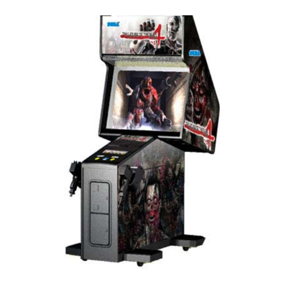
MINI DELUXE
SERVICE MANUAL
Before using this product, read this MANUAL carefully to understand the contents stated
herein.
After reading this MANUAL, be sure to keep it available nearby the product or somewhere
convenient in order to be able to refer to it whenever necessary.
MANUFACTURING DIVISION (U.K.)
Rev 1
Advertisement
Table of Contents
Troubleshooting

Subscribe to Our Youtube Channel
Related Manuals for Sega MINI DELUXE THE HOUSE OF THE DEAD 4


Summary of Contents for Sega MINI DELUXE THE HOUSE OF THE DEAD 4
- Page 1 420-6908-03UK Rev 1 MINI DELUXE SERVICE MANUAL • Before using this product, read this MANUAL carefully to understand the contents stated herein. • After reading this MANUAL, be sure to keep it available nearby the product or somewhere convenient in order to be able to refer to it whenever necessary. Manufactured in the UK by MANUFACTURING DIVISION (U.K.)
-
Page 2: Table Of Contents
CONTENTS BEFORE USING THIS PRODUCT .......................1 1.1. INSPECTIONS IMMEDIATELY AFTER TRANSPORTING THE PRODUCT TO THE LOCATION .2 INTRODUCTION TO THIS SERVICE MANUAL ...................4 HANDLING AND INSTALLATION PRECAUTIONS................5 NAME OF PARTS ..........................6 ACCESSORIES .............................7 ASSEMBLING............................8 6.1. SECURING IN PLACE (LEG ADJUSTER ADJUSTMENT) ............9 6.2. -
Page 3: Before Using This Product
Should any doors, lids or protective covers be damaged or lost, do not operate the product. SEGA is not liable in any whatsoever for any injury and/or damage caused by specification changes not designated by SEGA. -
Page 4: Inspections Immediately After Transporting The Product To The Location
INSPECTIONS IMMEDIATELY AFTER TRANSPORTING THE PRODUCT TO THE LOCATION Normally, at the time of shipment, SEGA products are in a state to allowing usage immediately after transporting to the location. Nevertheless, an irregular situation may arise during transportation preventing this. Before turning on the power, check the following points to ensure that the product has been transported safely. - Page 5 CONCERNING THE STICKER DISPLAY CONCERNING WARNING STICKERS SEGA product has stickers describing the product SEGA product has warning displays on manufacture number (Serial Number) and stickers, labels or printed instructions electrical specification. If you require service adhered/attached to or incorporated in the assistance you will require the Serial Number.
-
Page 6: Introduction To This Service Manual
HOUSE OF THE DEAD 4 MINI DELUXE, a new SEGA product. This manual is intended for those who have knowledge of electricity and technical expertise especially in IC’s, CRT’s, microprocessors etc.. Carefully read this manual to acquire sufficient knowledge before working on the machine. -
Page 7: Handling And Installation Precautions
HANDLING AND INSTALLATION PRECAUTIONS • Installation and commissioning should only be carried out by a QUALIFIED SERVICE PERONNEL. When installing or inspecting the machine, be very careful of the following points and pay attention to ensure that the player can enjoy the game safely. The game must NOT be installed under the following conditions: •... -
Page 8: Name Of Parts
NAME OF PARTS Width (cm) Depth (cm) Height (cm) Weight (kg) When Assembled 76.5 140.5 197.5 Approx. 180... -
Page 9: Accessories
ACCESSORIES The machine is supplied with an installation kit. Please ensure the following parts are supplied: PART NUMBER DESCRIPTION 440-CS0186UK STICKER C EPILEPSYB MULTI SAECE-XXX DECLARATION OF CONFORMITY HDF-1056UK DECAL BUTTON PLATE HDF MDX MULTI 540-0043-91 L-WRENCH FOR HEX SOC 3MM 601-11691 CARTON BOX LBG *401... -
Page 10: Assembling
ASSEMBLING • Perform the assembly work by following the procedure herein stated. Failing to comply with the instructions can cause an electric shock. • Assembling should be performed as per this manual. Since this is a complex machine, erroneous assembling can cause an electric shock or damage to the machine resulting in not functioning as per performance. -
Page 11: Securing In Place (Leg Adjuster Adjustment)
6.1. SECURING IN PLACE (LEG ADJUSTER ADJUSTMENT) • Make sure that all of the leg adjusters are in contact with the floor. If they are not, the cabinet may move causing an accident. This machine has 4 castors and 4 leg adjusters. When the installation position is determined, bring the leg adjusters to come into contact with the floor directly, make adjustments in a manner so that the castors will be raised approximately 5mm. -
Page 12: Power Supply, And Earth Connection
6.2. POWER SUPPLY, AND EARTH CONNECTION • Maintenance must only be carried out by Qualified Service Personnel. Ensure that the mains power is switch OFF and disconnected before attempting any work. The Transformer fitted to this machine is capable of accepting a wide range of voltages from 210V to 240V. This is factory set to 230V and, in normal operating conditions, should not need to be changed. -
Page 13: Machine Check
6.4. MACHINE CHECK • This operation should only be carried out by QUALIFIED SERVICE PERSONNEL. In the TEST MODE, ensure that the ASSEMBLY has been assembled correctly and that the CPU is in working order. In the TEST MODE perform the following tests. The JVS TEST screen displays information on the connected JVS I/O boards. - Page 14 MONITOR TEST Use MONITOR TEST to check the output of the monitor. Enter MONITOR TEST and the following color bars will be displayed. Press the TEST Button and the screen will change to the following crosshatch screen. Press the TEST Button to return to the System Test Menu screen.
- Page 15 a. INPUT TEST Select INPUT TEST to display the following screen and check the status of input devices. This test should be used periodically to check that each input device is functioning correctly. INPUT TEST PLAYER1 PLAYER2 START GUN TRIGGER GUN BUTTON GUN SPEED X GUN SPEED Y...
- Page 16 b. OUTPUT TEST Select OUTPUT TEST to display the following screen and check the status of output devices. This test should be used periodically to check that the lamps are functioning correctly. Use the SERVICE Button to move the cursor to the desired test item. Press the TEST Button to enter the selected item’s test.
- Page 17 c. PLAYER1 GUN ADJUSTMENT/PLAYER2 GUN ADJUSTMENT This item adjusts the Player 1 gun sight. (This is the same for “PLAYER2 GUN ADJUSTMENT”.) Select PLAYER1 GUN ADJUSTMENT on the Gun Calibration Setting screen and press the TEST Button. NOTE: “PLEASE SHOOT GRID WITH PLAYER1 GUN” on the screen will flash. PLAYER1 GUN ADJUSTMENT ←PLEASE SHOOT GRID WITH PLAYER1 GUN PRESS TEST TO EXIT...
- Page 18 Aim and fire at the mark to the lower right. The mark to the lower right will disappear, and the same mark will be displayed in the center. (Press the TEST Button to return to the Gun Calibration Setting screen.) PLAYER1 GUN ADJUSTMENT ↑PLEASE SHOOT GRID WITH PLAYER1 GUN PRESS TEST TO EXIT...
- Page 19 PLAYER1 GUN ADJUSTMENT PLAYER1 GUN MARK CHECKING +OUT OF SCREEN P1+ TEST : TO MEMORIZE SERVICE : TO CANCEL Point the Control Unit (Gun) at the screen and a gun mark will be displayed. Check to make sure that the gun can aim right up to the edges of the frame.
-
Page 20: Precautions To Be Taken When Moving The Machine
PRECAUTIONS TO BE TAKEN WHEN MOVING THE MACHINE • When moving the machine, be sure to pull out the plug from the power supply. Moving the machine with the plug as is inserted can cause the power cord to be damaged, resulting in a fire and or electric shock. •... -
Page 21: Operation
OPERATION For the safe operation of the product, be sure to comply with the following precautions. PRECAUTIONS TO BE HEEDED FOR OPERATION • Check if all of the leg adjusters are in contact with the surface. If they are not, the cabinet can move, causing an accident. -
Page 22: Troubleshooting
8.1. TROUBLESHOOTING • These procedures should only be carried out by QUALIFIED SERVICE PERSONNEL. If a problem occurs, first check the wiring connections. PROBLEMS CAUSE COUNTERMEASURES When the main The power is not ON. Firmly insert the plug into the outlet. switch is turned ON, the machine is not activated... -
Page 23: How To Play
HOW TO PLAY The following explanations apply to the product when functioning properly. If the product operates differently from the following contents, a fault may have occurred. Immediately look into and eliminate the cause of the fault to ensure proper operation. The fluorescent light in the billboard and the cold-cathode tube in the lighting unit are always on whenever the power is turned on. -
Page 24: Game Outline
9.1. GAME OUTLINE • Insert a coin and a credit will be added to the credit indicator below the screen. When enough coins have been entered for one play, the “INSERT COIN(S)” message below the screen will change to “PRESS START BUTTON,” and both START buttons will flash. •... - Page 25 The gun holds 30 shots. When empty, the message “RELOAD” will appear on the screen. The player can reload the gun by gently shaking it or by pointing it outside of the screen. The gun can be reloaded by gently shaking it or pointing it outside of the screen even if bullets remain in the gun. Only the displayed number of grenades may be used.
- Page 26 As the game progresses, players will be faced with enemies grabbing them and attempting to push them over. To survive this danger, the player must shake the gun controller to fill up the on-screen meter within the time limit. If the player fails to do so they will take damage, reducing their number of lives, and risk being pushed over and taking further damage.
-
Page 27: Items
9.2. ITEMS Other items can also be found during the game. “Medical Kit” “Mini Magician” Increases life by one. Increases a player’s score. “Gold Coin” “Golden Frog” Increases a player’s score. Increases a player’s score. “Silk Hat” “Toy’s Bus” Increases a player’s score. Increases a player’s score. -
Page 28: Play Hints
9.3. PLAY HINTS ● Aim for the head! Enemies in every stage, aside from boss characters, will lose the most life when shot in the head. Therefore, shooting enemies accurately in the head is the fastest way to defeat them. ●... -
Page 29: Maintenance Instructions
MAINTENANCE INSTRUCTIONS 10.1. EXPLANATION OF TEST AND DATA DISPLAY Use the switches on the VTS to enter the TEST MODE. This will allow you to carry out post installation and periodic checks and adjustments. The following section details the function of each of the tests: •... -
Page 30: Vts Assembly
10.1.1.VTS ASSEMBLY • Do not touch places other than those specified. Touching places not specified could cause an electric shock or short circuit. TEST BUTTON SERVICE BUTTON Opening the Coin Chute door will reveal the VTS Assembly shown above. The function of each switch is as follows. -
Page 31: System Test Mode
10.1.2.SYSTEM TEST MODE System Test Mode can be used to check the information or the operation of the LINDBERGH board, adjust Monitor colour, and perform coin/credit settings. • When setting changes are made within TEST MODE, be sure to exit from TEST MODE using the exit options. - Page 32 a. SYSTEM INFORMATION The SYSTEM INFORMATION screen displays system information. The following information is displayed on this screen. ● MOTHER BOARD - SERIAL NO.: The serial number of the game board. - KERNEL VERSION: The system’s OS version. - BOOT VERSION: The boot program version.
- Page 33 b. STORAGE INFORMATION The STORAGE INFORMATION screen displays information on the game contained within the program installer device. This screen is also used when uninstalling the game contained within the program installer device. Until preparations to launch the game are complete, a “now checking” screen will be displayed and uninstall cannot be performed.
- Page 34 c. JVS TEST The JVS TEST screen displays information on the connected JVS I/O boards. Select INPUT TEST to display input data for the currently displayed JVS I/O board. (See “d - JVS INPUT TEST”) Select NEXT NODE to display information on the next NODE. If no JVS I/O boards are connected, the message “NO JVS NODE”...
- Page 35 d. JVS INPUT TEST Use the JVS INPUT TEST to test the JVS input. The hexadecimal input information from the JVS I/O board will be displayed in real time. The following information is displayed on this screen. ● SYSTEM: System switch input data ●...
- Page 36 e. MONITOR TEST Use MONITOR TEST to check the output of the monitor. Enter MONITOR TEST and the following color bars will be displayed. Press the TEST Button and the screen will change to the following crosshatch screen. Press the TEST Button to return to the System Test Menu screen.
- Page 37 f. SPEAKER TEST Use SPEAKER TEST to check the output of each speaker by having them each emit a test sound. Select each speaker with the cursor and press the TEST Button to turn that speaker ON or OFF. When set to ON a test sound will be emitted from that speaker. It is possible to set multiple speakers to emit the test sound at the same time.
- Page 38 g. COIN ASSIGNMENTS Use COIN ASSIGNMENTS to alter the credit settings. The game will award players the number of credits determined here. Settings will only be saved if they have been changed. Changing the credit settings will also clear the current inserted coins value. If no baseboard is present, this option will not appear on the main menu.
- Page 39 g-3 COIN CHUTE #1 COIN TO CREDIT RATE (Coin and credit conversion rate 1) 1 COIN(S) COUNT AS 1 CREDIT(S) 1 coin counts as 1 credit 2 COIN(S) COUNT AS 1 CREDIT(S) 2 coins count as 1 credit 3 COIN(S) COUNT AS 1 CREDIT(S) 3 coins count as 1 credit 4 COIN(S) COUNT AS 1 CREDIT(S) 4 coins count as 1 credit...
- Page 40 g-6 GAME COST SETTING Use the COIN ASSIGNMENTS GAME COST SETTING screen to set the cost (number of required credits) that the game program will use to determine if there are enough credits to play the game. A total of 8 game costs can be defined. The game cost is defined by the BOOT ID, and when the second boot recognizes the game, the game cost defined by the BOOT ID will be displayed.
- Page 41 CLOCK SETTING Use CLOCK SETTING to set the date and time. Use the SERVICE Button to move the cursor to the category that you wish to change and press the TEST Button to increase that value. Holding the TEST Button down will make the value continuously increase. Changes will come into effect when you exit.
- Page 42 i. NETWORK SETTING Use NETWORK SETTING to determine network settings or to test the network. This product does not use the network function. You must use the following factory settings. ● NETWORK TYPE: MAIN ● MAIN NETWORK: No need to set. The following information is displayed on this screen.
- Page 43 Select a category on the NETWORK SETTING (Setting Menu) and the following screen will be displayed. However, since this product does not use network function, this manual does not contain instructions for performing network settings or tests. NETWORK SETTING Screen NETWORK TEST Screen j.
-
Page 44: Game Test Mode
10.1.3.GAME TEST MODE • When setting changes are made within TEST MODE, be sure to exit from TEST MODE using the exit options. If you turn the power off and then on without having exited correctly the changes you made will not take effect. Game Test Mode allows game settings to be altered, Control Units (Guns) to be calibrated and game data to be checked. - Page 45 a. INPUT TEST Select INPUT TEST to display the following screen and check the status of input devices. This test should be used periodically to check that each input device is functioning correctly. INPUT TEST PLAYER1 PLAYER2 START GUN TRIGGER GUN BUTTON GUN SPEED X GUN SPEED Y...
- Page 46 b. OUTPUT TEST Select OUTPUT TEST to display the following screen and check the status of output devices. This test should be used periodically to check that the lamps are functioning correctly. Use the SERVICE Button to move the cursor to the desired test item. Press the TEST Button to enter the selected item’s test.
- Page 47 • Display of GUN MOTOR1 and GUN MOTOR2 options can be turned on or off using the DIP-SW. For cabinets with vibration motors attached to the Control Units (Guns), turn on display of the GUN MOTOR1 and GUN MOTOR2 under DIP-SW settings to alter these settings.
- Page 48 c. GAME ASSIGNMENTS Select GAME ASSIGNMENTS to display the current game settings and make changes. Changes to settings are not enabled until Game Assignments is exited. After changing settings, be sure to exit the Test Mode. Use the SERVICE Button to move the cursor to the desired test item. Press the TEST Button to enter the selected item’s test.
- Page 49 d. GUN CALIBRATION SETTING Select GUN CALIBRATION SETTING to display the following screen. Perform the sight settings for the guns to be used in the game. Use the SERVICE Button to move the cursor to the desired test item. Press the TEST Button to enter the selected item’s test.
-
Page 50: Gun Mark Check
d-1 GUN MARK CHECK This checks gun sights. Select GUN MARK CHECK on the Gun Calibration Setting screen and press the TEST Button. GUN MARK CHECK +OUT OF SCREEN P1+ +OUT OF SCREEN P2+ PRESS TEST TO EXIT ● 1P Gun Cross This is displayed when the gun is pointed at the screen. -
Page 51: Player1 Gun Adjustment
d-2 PLAYER1 GUN ADJUSTMENT/PLAYER2 GUN ADJUSTMENT This item adjusts the Player 1 gun sight. (This is the same for “PLAYER2 GUN ADJUSTMENT”.) Select PLAYER1 GUN ADJUSTMENT on the Gun Calibration Setting screen and press the TEST Button. NOTE: “PLEASE SHOOT GRID WITH PLAYER1 GUN” on the screen will flash. PLAYER1 GUN ADJUSTMENT ←PLEASE SHOOT GRID WITH PLAYER1 GUN PRESS TEST TO EXIT... - Page 52 Aim and fire at the mark to the lower right. The mark to the lower right will disappear, and the same mark will be displayed in the center. (Press the TEST Button to return to the Gun Calibration Setting screen.) PLAYER1 GUN ADJUSTMENT ↑PLEASE SHOOT GRID WITH PLAYER1 GUN PRESS TEST TO EXIT...
- Page 53 PLAYER1 GUN ADJUSTMENT PLAYER1 GUN MARK CHECKING +OUT OF SCREEN P1+ TEST : TO MEMORIZE SERVICE : TO CANCEL Point the Control Unit (Gun) at the screen and a gun mark will be displayed. Check to make sure that the gun can aim right up to the edges of the frame.
-
Page 54: Player1 Gun Default Adjustment
d-3 PLAYER1 GUN DEFAULT ADJUSTMENT/PLAYER2 GUN DEFAULT ADJUSTMENT This item adjusts the sight settings to those at the time of shipment. (This is the same for “PLAYER2 GUN DEFAULT ADJUSTMENT”.) Select PLAYER1GUN DEFAULT ADJUSTMENT on the Gun Calibration Setting screen and press the TEST Button. -
Page 55: Player2 Gun Adjustment
e. GUN SPEED SETTING Adjust the volume settings for the Control Unit’s (Gun’s) speed sensors. Select GUN SPEED SETTING on the Game Test Mode screen and press the TEST Button to display the following screen. Use the SERVICE Button to move the cursor to the desired test item. Press the TEST Button to enter the selected item’s test. - Page 56 e-1 GUN SPEED CHECK Checks the registered speed when the Control Units (Guns) are shaken. Select GUN SPEED CHECK on the Gun Speed Setting screen and press the TEST Button to display the following screen. GUN SPEED CHECK P1 GUN SPEED P2 GUN SPEED GUN SPEED X GUN SPEED X...
- Page 57 e-2 PLAYER1 GUN SPEED ADJUSTMENT/ PLAYER2 GUN SPEED ADJUSTMENT • Pay attention to your surroundings when moving the Control Unit (Gun) during speed adjustment so as not to hit people or objects around you. You may hurt others or yourself if due caution is not taken. •...
- Page 58 PLAYER1 GUN SPEED ADJUSTMENT NOW CALCULATING Press the TEST Button and the message “NOW CALCULATING” will be displayed on the screen, and it will then proceed automatically to the next screen. PLAYER1 GUN SPEED ADJUSTMENT PLAYER1 GUN SPEED CHECKING P1 GUN SPEED GUN SPEED X MAX 7f GUN SPEED Y...
- Page 59 PLAYER1 GUN SPEED ADJUSTMENT COMPLETED Press the TEST Button and the message “COMPLETED” will be displayed on the screen, and it will then proceed automatically to the Gun Speed Setting screen.
- Page 60 PLAYER1 GUN SPEED DEFAULT ADJUSTMENT/ PLAYER2 GUN SPEED DEFAULT ADJUSTMENT Returns the speed setting to the default factory setting. (This is the same for “PLAYER2 GUN SPEED DEFAULT ADJUSTMENT”.) Select PLAYER1 GUN SPEED DEFAULT ADJUSTMENT on the Gun Speed Setting screen and press the TEST Button to display the following screen.
- Page 61 f. BOOKKEEPING Select BOOKKEEPING on the Game Test Mode screen to display the three screens of operating status data. BOOKKEEPING PAGE1/3 COIN 1 COIN 2 TOTAL COINS COIN CREDITS SERVICE CREDITS TOTAL CREDITS PRESS TEST TO CONTINUE The display items for the screen (PAGE 1/3) are as follows. ●...
- Page 62 Press the TEST Button to display the next screen (PAGE 2/3). BOOKKEEPING PAGE2/3 NUMBER OF GAMES FIRST PLAY CONTINUE PLAY TOTAL TIME 0D 00H 00M PLAY TIME 0D 00H 00M AVERAGE PLAY TIME PRESS TEST TO CONTINUE The display items for the screen (PAGE 2/3) are as follows. ●...
- Page 63 Press the TEST Button to display the next screen (PAGE 3/3). BOOKKEEPING PAGE3/3 GAME HISTOGRAM 0M 00S 0M 29S 0M 30S 0M 59S 1M 00S 1M 29S 1M 30S 1M 59S 2M 00S 2M 29S 2M 30S 2M 59S 3M 00S 3M 29S 3M 30S 3M 59S...
- Page 64 g. BACKUP DATA DLEAR Select BACKUP DATA CLEAR to clear the contents of BOOKKEEPING in the Game Test Mode and the game score. BACKUP DATA CLEAR YES(CLEAR) NO (CANCEL) -> SELECT WITH SERVICE AND PRESS TEST To clear data, use the SERVICE Button to move the cursor to YES (CLEAR) and then press the TEST Button.
-
Page 65: Error Codes
10.1.4.ERROR CODES Error 01 DISPLAY Game Program Not Found. CAUSE The keychip is not connected. COUNTERMEASURE Check that the keychip is connected correctly. Check that the keychip is not inserted the wrong way or that the keychip from a different system is not inserted. - Page 66 Error 12 DISPLAY JVS I/O board does not fulfill the game spec. CAUSE The correct I/O board is not connected. COUNTERMEASURE Use an I/O board that provides the proper input/output for the game. Error 14 DISPLAY Network firmware version does not fulfill the game spec. Required version XX.XX.
- Page 67 Error 29 DISPLAY Cannot Control DVD Drive. CAUSE The DVD drive cannot be controlled. COUNTERMEASURE The DVD drive may be damaged. Error 31 DISPLAY Storage Device Not Enough. CAUSE The program installer device does not have enough space. COUNTERMEASURE Send the LINDBERGH board in for repair with the keychip still in place. Error 32 DISPLAY Installing Game Program Failed.
- Page 68 Error 43 DISPLAY IP Address Not Assigned. CAUSE An IP Address could not be obtained from the DHCP server. COUNTERMEASURE Check the network settings. Set IP Address and other settings. Check that the network cable has not been pulled out. Error 44 DISPLAY Game Program Not Found on Server.
-
Page 69: Coin Mech Installation And Credit Board Set Up
10.2. COIN MECH INSTALLATION AND CREDIT BOARD SET UP 10.2.1.INTRODUCTION Game credits between the Coin Mechanism and the game board for this machine are controlled by a VTS board. This electronic circuit allows the price of play to be set for a range of different countries. These functions are set on Dual In Line (DIL) PCB mounted switches. - Page 70 Illustration shows VTS PCB. All COIN ASSIGNMENTS are carried out and processed by the VTS Board. This game uses a single SR3 Coin Validator (if supplied). This Validator will connect into port A as indicated by the illustration above. All Credit settings are configured via the DIP switches also located on the VTS Board (please refer to later on in this manual for the appropriate switch settings).
-
Page 71: Vts Credit Board Option Settings
10.2.2.VTS CREDIT BOARD OPTION SETTINGS Credit Board Mode Settings Switch 3 Country Setting Switch 3 Setting Coin Validator Programming C120/SR3 Only SW1 SW2 SW3 SW4 SW5 SW6 COIN1 COIN2 COIN3 COIN4 COIN5 COIN6 COIN7 COIN8 COIN9 COIN10 COIN11 COIN12 Coin Controls £1 50p new 50p old... -
Page 72: Price Of Play Settings Uk
10.2.3.PRICE OF PLAY SETTINGS UK Price Bonus DIL Switch 1 Switch 1 Switch 2 Switch 3 Switch 4 Switch 5 No Bonus 6 = 50p No Bonus 3 = 50p 6 = £1 12 =£2 No Bonus 1.66 = 50p 4 = £1 8 = £2 2 = 50p... -
Page 73: Price Of Play Settings Euro
10.2.4.PRICE OF PLAY SETTINGS EURO Price Bonus DIL Switch 1 Switch 1 Switch 2 Switch 3 Switch 4 Switch 5 10¢ No Bonus 10¢ 6 = 50¢ 20¢ No Bonus 20¢ 3 = 50¢ 6 = €1 12 =€2 30¢ No Bonus 30¢... -
Page 74: Controller Unit (Gun)
CONTROLLER UNIT (GUN) - Page 75 If there appears to be a problem with the gun and adjustment in Test Mode makes no difference, part of the gun is most likely broken. Use the following instructions to take the gun apart and replace the broken part. The exterior casing, comprised of cover L and cover R, must be opened up in order to change interior parts.
-
Page 80: Replacement Of Flourescent Lamps
REPLACEMENT OF FLOURESCENT LAMPS • When performing the work, be sure to sure power off. Working with power on can cause an electric shock or short circuit accident. • Hot fluorescent lamp can cause burns. Be very careful when replacing them. BILLBOARD LAMP REPLACEMENT 1) Take off screws and remove the Upper and Lower Billboard Sash. - Page 81 START LAMP REPLACEMENT • Following the procedure in the “Gun Cabinet Lamp replacement” to remove the ASSY CONTROL PANEL. • Locate the ASSY SWITCH with the defective lamp and twist to remove. • Pull the bulb from the lamp housing and replace by push to fit.
-
Page 82: Periodic Inspection Table
PERIODIC INSPECTION TABLE The items listed below require periodic check and maintenance to retain the performance of this machine and to ensure safety business operation. • Be sure to check ones a year to see if Power Cords are damaged, the plug is securely inserted, dust is accumulated between the Socket Outlet and the Power Plug, etc. -
Page 83: Troubleshooting
TROUBLESHOOTING • In order to prevent an electrical shock, be sure to turn power off before performing work by touching the interior parts of the product. • Be careful so as not to damage wirings Damaged wiring can cause an electrical shock or short circuit accident. - Page 84 PROBLEMS CASE COUNTERMERMEASURES During game, graphics are The guns may not be aligned Enter GAME TEST MODE and displayed on the screen, but no correctly in TEST. re-align both guns and check. action of left/right guns. The colour of image on Incorrect monitor adjustment.
-
Page 85: Game Board
GAME BOARD • In order to prevent electric shock and short circuit hazards, be sure to turn power off before performing work. • Be careful not to damage the wires. Damaged wires may cause electric shock or short circuit or present a fire risk. •... -
Page 86: Removing The Game Board
15.1. REMOVING THE GAME BOARD Turn the Main SW off. Remove the Side Door from the left-hand side of the cabinet by using the Master Key and taking off the 2 screws. Remove all the associated harnesses then remove the 4 screws retaining the Lindbergh Game Board. -
Page 87: Shipping The Game Board
15.2. SHIPPING THE GAME BOARD • When returning the GAME BOARD for repair or replacement, be sure to package the entire ASSY SHIELD CASE in the original card transit box - THERE ARE NO USER-SERVICEABLE PARTS INSIDE. • Failure to return the GAME BOARD in this manner may invalidate the warranty. Wrap the ASSY GAME BOARD with the packaging material and put it in the original transit box as shown. -
Page 88: Design Related Parts
DESIGN RELATED PARTS For the Warning Display stickers, refer to Section 1. Seq. No. Part Number Description ****401 HDF-1072-CUK STICKER SIDE L 02 ****403 HDF-1072-EUK STICKER SIDE R 02 ***20 HDF-1502-BUK STICKER SIDE L 01 ***21 HDF-1502-DUK STICKER SIDE R 01 ***22 HDF-1513-AUK STICKER SIDE DOOR L... -
Page 89: Part List
PART LIST 17.1. ASSY TOP - (HDF-00002KUK) Seq. Number Component Part Description Component Reference HDF-10001UK ASSY CABINET MDX 421-7987-HDF-M STICKER ELEC SPEC HDF MDX NEXT TO AC UNIT 421-7988-91UK STICKER SERIAL NUMBER UK NEAR AC 421-7020UK STICKER CAUTION FORK PK0382 COVER SHRINK MDX PK0383 PALLET HDF MDX... -
Page 90: Assy Cabinet Mdx - (Hdf-10001Uk)
17.2. ASSY CABINET MDX – (HDF-10001UK) Seq. Number Component Part Description Component Reference HDF-1500UK ASSY CABINET LOWER HDF-1540UK ASSY CNTRL PNL HDF-1095UK ASSY LIGHT BOX PP1087 BOX CASH FOR MINI DOOR **201 000-T00525-0B M5X25 MSCR TH BLK (3)-8 **202 000-P00616-W M6X16 MSCR PAN W/FS PAS (4)-2 **206... -
Page 91: Assy Cabinet Lower - (Hdf-1500Uk)
17.3. ASSY CABINET LOWER – (HDF-1500UK) Seq. Number Component Part Description Component Reference ***1 HDF-1501UK ASSY SUB CABINET LOWER ***2 HDF-1530UK ASSY AC UNIT ***3 HDF-1520UK ASSY FOOT BASE ***4 HDF-4500UK ASSY ELEC LEFT ***5 HDF-2100-02 CONTROL UNIT UK ***6 HDF-4700UK ASSY POWER BASE ***7... - Page 92 ASSY CABINET LOWER – (HDF-1500UK) continued Seq. Number Component Part Description Component Reference ***21 HDF-1502-DUK STICKER SIDE R 01 NOT SHOWN ***22 HDF-1513-AUK STICKER SIDE DOOR L NOT SHOWN ***23 HDF-1513-BUK STICKER SIDE DOOR R NOT SHOWN ***24 ORP-2372UK CAM CRKD 9 L34 BATON 690-ZB34 NOT SHOWN ***25 HDF-1511UK...
-
Page 93: Assy Sub Cabi Monitor - (Hdf-1071Uk)
17.4. ASSY SUB CABI MONITOR – (HDF-1071UK) Seq. Component Part Description Component Reference Number off ****1 HDF-1072-AUK MONITOR BOX BLANK UK ****2 GBN-1073UK BACK DOOR ****3 HDF-1074UK MONITOR SUPPORT ****4 GBN-1075 JOINT BEAM ****9 253-5460-01 VENT AIR BLACK ****10 HDF-1083UK NUT PLATE ****12 LB1102... -
Page 94: Assy Monitor Uk - (Hdf-1070Uk)
17.5. ASSY MONITOR UK – (HDF-1070UK) - Page 95 ASSY MONITOR UK – (HDF-1070UK) continued……….. Seq. Number Component Part Description Component Reference ***1 HDF-1071UK ASSY SUB CABI MONITOR ***2 GBN-1077 SASH UPPER ***3 HDF-1082UK FRONT SCREEN ***4 HDF-1080UK SCREEN RETAINER LOWER ***5 HDF-1081UK ADJUST PANEL ***7 HDF-1079UK BILLBOARD PLATE ***11 421-7501-17UK STICKER FL20W...
-
Page 96: Assy Sensor Mtg - (Hdf-1085Uk)
17.6. ASSY SENSOR MTG – (HDF-1085UK) Seq. Component Part Description Component Reference Number off ****1 HDF-1086UK BRKT SENSOR MTG ****2 JPT-1082 IR COVER ****3 838-13145R02 LED BD GUN SENSE HOD ****201 050-U00300 M3 NUT NYLOK PAS ****202 068-330808-PN M3 WSHR 8OD FLT NYLON 17.7. -
Page 97: Assy Foot Base - (Hdf-1520Uk)
17.8. ASSY FOOT BASE – (HDF-1520UK) Seq. Component Part Description Component Reference Number off ****1 HDF-1521UK FOOT BASE ASSY ****101 601-5699UK-01 LEG ADJ M16X100 ****102 MA1019 CASTOR 75 ****201 030-000620-S M6X20 BLT W/S PAS (102)-16 ****202 060-F00600 M6 WSHR FORM A FLT PAS (102)-16 17.9. -
Page 98: Assy Control Panel - (Hdf-1540Uk)
17.10. ASSY CONTROL PANEL – (HDF-1540UK) Seq. Component Part Description Component Reference Number off HDF-1053UK FASCIA MOULDING LOWER CABINET HDF-1054UK FASCIA SUPPORT HDF-1055UK BUTTON PLATE HDF-1057UK DECAL FASCIA UPPER **101 509-SPYU-YE SW PB W/LAMP 6V YELLOW OVAL **102 OS1230 FOAM STRIP 2mm X 10mm NOT SHOWN **201 000-T00420-0B... -
Page 99: Assy Power Base - (Hdf-4700Uk)
17.12. ASSY POWER BASE – (HDF-4700UK) Seq. Component Part Description Component Reference Number off ****1 HDF-4701UK BASE POWER ****4 HDF-0485UK BRKT PWR SUPPLY (101)-2 ****101 400-5457-91 SW REGU ATX/JVS ****102 560-LBGH-01UK XFMR LINDBURGH 230-100V 8A ****103 839-1160 DC TERMINAL BD ****104 280-A01264-WX ROUTER TWIST D12 SO6.4 WOOD X... -
Page 100: Assy Elec Left - (Hdf-4500Uk)
17.13. ASSY ELEC LEFT – (HDF-4500UK) Seq. Component Part Description Component Reference Number off ****1 HDF-4501UK ELEC BASE LEFT ****2 844-0002D-15 ASSY CASE LBG L 1GB HDF EXP2 ****3 610-0727-0003 DVD SOFT KIT HDF ****101 837-14505 I/O CONTROL BD FOR JVS ****102 838-14465R IC BD GUN SENCE NEW EDIT DX... -
Page 101: Assy Elec Right - (Hdf-4600Uk)
17.14. ASSY ELEC RIGHT – (HDF-4600UK) Seq. Component Part Description Component Reference Number off ****1 HDF-4601UK ELEC BASE RIGHT ****101 400-5421-05012 SW REGU LCA50S-12 ****102 838-CA-150 AMP 2 CH 12V CIE CA-150/S ****103 OS1011 PCB FEET RICHCO LCBS-L-5-01 (101)-4 ****104 280-A01264-WX ROUTER TWIST D12 SO6.4 WOOD X ****201... -
Page 102: Wire Colour Code Table
WIRE COLOUR CODE TABLE THE WIRE COLOUR CODE IS AS FOLLOWS: PINK SKY BLUE BROWN PURPLE LIGHT GREEN Wires other than those of any of the colours listed above will be displayed by 2 alphanumeric characters: BLUE YELLOW GREEN WHITE ORANGE BLACK GREY... -
Page 103: Appendix A - Electrical Schematic
APPENDIX A - ELECTRICAL SCHEMATIC The following page contains the electrical schematic for this machine. - Page 107 SEGA AMUSEMENTS EUROPE Suite 3a Oak House, 12-22 West Street Epsom Surrey United Kingdom, KT18 7RG. Telephone: +44 (0) 1372 731 820 Fax: +44 (0) 1372 731 849 © SEGA 2006...
Need help?
Do you have a question about the MINI DELUXE THE HOUSE OF THE DEAD 4 and is the answer not in the manual?
Questions and answers