Table of Contents
Advertisement
Quick Links
Pt. No: HDF-6908-02UK
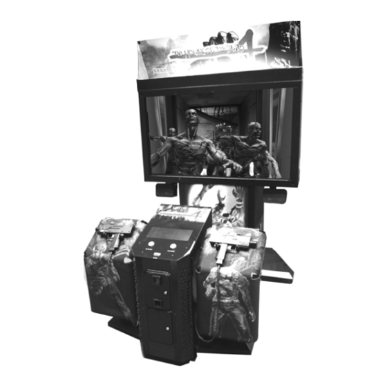
HOUSE OF THE DEAD 4 SUPER DELUXE
•
•
Manufactured in the UK by
OWNERS MANUAL
Before using this product, read this MANUAL carefully to understand the contents
stated herein.
After reading this MANUAL, be sure to keep it available nearby the product or
somewhere convenient in order to be able to refer to it whenever necessary.
MANUFACTURING DIVISION (U.K.)
Rev 1.00
Advertisement
Table of Contents
Troubleshooting

Related Manuals for Sega HOUSE OF THE DEAD 4 SUPER DELUXE


Summary of Contents for Sega HOUSE OF THE DEAD 4 SUPER DELUXE
- Page 1 Pt. No: HDF-6908-02UK Rev 1.00 HOUSE OF THE DEAD 4 SUPER DELUXE OWNERS MANUAL • Before using this product, read this MANUAL carefully to understand the contents stated herein. • After reading this MANUAL, be sure to keep it available nearby the product or somewhere convenient in order to be able to refer to it whenever necessary.
-
Page 2: Table Of Contents
Contents Before using this product ........................1 1.1. Inspection on immediately transporting the product to location............2 Introduction to this service manual ......................4 Installation and service instructions .......................5 3.1. Handling and precautions ........................5 3.1.1. Precautions when moving the machine ..................6 3.2. Name of general parts........................7 3.3. - Page 3 8.5.2. Player 1 & Player 2 gun speed adjustment................72 8.5.3. Player 1 & Player 2 gun speed default adjustment..............74 8.6. Bookkeeping.............................75 8.7. Backup data clear ..........................77 Gun control unit............................78 9.1. Replacing the microswitch .......................80 9.2. Replacing the sensor unit.........................82 9.3. Replacing the speed sensor unit......................83 Projector...............................84 10.1.
-
Page 4: Before Using This Product
Should any doors, lids or protective covers be damaged or lost, do not operate the product. SEGA is not liable in any whatsoever for any injury and/or damage caused by specification changes not designated by SEGA. -
Page 5: Inspection On Immediately Transporting The Product To Location
Inspection on immediately transporting the product to location QUALIFIED SERVICE PERSONNEL should only carry out inspection. Normally, at the time of shipment, SEGA products are in a state to allowing usage immediately after transporting to the location. Nevertheless, an irregular situation may arise during transportation preventing this. - Page 6 CONCERNING THE STICKER DISPLAY CONCERNING WARNING STICKERS SEGA product has stickers describing the product SEGA product has warning displays on manufacture number (Serial Number) and stickers, labels or printed instructions electrical specification. If you require service adhered/attached to or incorporated in the assistance you will require the Serial Number.
-
Page 7: Introduction To This Service Manual
HOUSE OF THE DEAD 4 SUPER DELUXE, a new SEGA product. This manual is intended for those who have knowledge of electricity and technical expertise especially in IC’s, CRT’s, microprocessors etc.. Carefully read this manual to acquire sufficient knowledge before working on the machine. -
Page 8: Installation And Service Instructions
Installation and service instructions QUALIFIED SERVICE PERSONNEL should only carry out installation and commissioning of this product. 3.1. Handling and precautions When installing or inspecting the machine, be very careful of the following points and pay attention to ensure that the player can enjoy the game safely. The game must NOT be installed under the following conditions: •... -
Page 9: Precautions When Moving The Machine
3.1.1. Precautions when moving the machine When moving the machine, be sure to pull out the plug from the power supply. Moving the machine with the plug still inserted can cause the power cord to be damaged, resulting in a fire and/or electric shock. When moving the machine on the floor, retract the adjusters, and ensure that the casters make contact with the floor. -
Page 10: Name Of General Parts
3.2. Name of general parts Width (cm) Length (cm) Height (cm) Weight (kg) ASSY DLP 200kg approx ASSY GUN CABI 150kg approx When Assembled 350kg approx... -
Page 11: Installation Parts And Accessories
3.3. Installation parts and accessories The machine is supplied with an installation kit. Please ensure the following parts are supplied: PT NUMBER DESCRIPTION 440-CS0186UK STICKER C EPILEPSY MULTI SAECE-135 DECLARATION OF CONFORMITY HDF-2003UK DECAL INST PLATE HDF SDX MULTI 540-0043-91 L-WRENCH FOR HEX SOC 3MM 540-0006-01 WRENCH M4 TMP PRF... -
Page 12: Shipping The Game Board
3.4. Shipping the game board • When returning the GAME BOARD for repair or replacement, be sure to package the entire ASSEMBLY in the original card transit box - THERE ARE NO USER- SERVICEABLE PARTS INSIDE. • Failure to return the GAME BOARD in this manner may invalidate the warranty. Wrap the ASSY GAME BOARD with the packaging material and put it in the original transit box as shown. -
Page 13: Precautions Regarding Installation And Location
3.5. Precautions regarding installation and location Perform the assembly by following the procedure herein stated. Failure to comply with the instructions, for example, inserting the plug into an outlet at a stage not mentioned in this manual can cause an electric shock Assembling should be performed as per this manual. -
Page 14: Operation Area
Do not allow objects to block the ventilation ports. It can cause generation of heat and a fire. SEGA shall not be held responsible for damage or compensation for damage to a third party, resulting from the failure to observe this instruction. - Page 15 Step 1 (Assemble the machine) • This operation should only be carried out by QUALIFIED SERVICE PERSONNEL. Step 1 • Remove the JOINT COVER (HDF- 1031UK) from over the joint of the 2 cabinets (2x M5x16 PAN PAS BLK and 2x M6x50 HEX BOLT BLK.) Gun Cabinet •...
- Page 16 • Feed the 6 and final harness up through the inside rear of the DLP cabinet and connect into the USB port on the Lindbergh CPU as shown in picture (left). • Secure DLP and GUN Cabinets together using 2x M8x30 Hex Bolt and 2x M8x65 Hex Bolt •...
- Page 17 Step 2 (Leg levelling procedure) Make sure all of the leg adjusters are in contact with the floor. If they are not the machine may move and cause injury. This operation requires 2 people. QUALIFIED SERVICE PERSONNEL should only carry out this operation. The cabinet is equipped with 8 casters (4 for DLP Base and 4 for Cabinet) and 6 adjusters (4 for DLP Base and 2 for Cabinet).
- Page 18 Ensure adequate ventilation is maintained as detailed below.
- Page 19 Step 3 (Billboard installation procedure) One person alone cannot perform the installation of the billboard assembly. Seek assistance before attempting this operation. QUALIFIED SERVICE PERSONNEL should only carry out this operation. • Fit the SUPPORTS L&R (HDF-0454UK and HDF-0455UK) and the BANNER ASSEMBLY L&R (HDF_0405UK and HDF_0406UK) to the Billboard Assembly using 8x M6x20 BLT W/S BLK and 8x M6...
- Page 20 • Place BILLBOARD PLATE (HDF- 0453UK) on the back of the SUPPORTS L&R and secure along the bottom edge using 4x M6x12 MCSR PAN W/FS PAS. • Remove the END CAPS BANNER (HDF- 0406UK) from both BANNER SUPPORTS. • Slide both BANNERS L&R (HDF-0403UK & HDF-0404UK) onto the supports and re- secure the END CAPS BANNER.
- Page 21 Step 4 (AC wiring and connection procedure) • Be sure that the machine is not connected to the mains supply before attempting this operation • QUALIFIED SERVICE PERSONNEL should only carry out this operation. Be sure to independently use the power supply socket outlet equipped with an Surge Suppressor.
-
Page 22: Connection To The Power Supply
3.6.1. Connection to the power supply • Be sure that the machine is not connected to the mains supply before attempting this operation • QUALIFIED SERVICE PERSONNEL should only carry out this operation. 1. Ensure that the main switch is OFF. 2. -
Page 23: Connecting The Dvd Drive (Software Installation)
3.6.2. Connecting the DVD drive (software installation) The software for this product is pre-loaded from the factory. The information and guide lines within this chapter are for reference purposes only. These procedures will only be implemented if the LINDBERGH is replaced or the SOFTWARE is updated. For safety's sake, prepare to perform the software install prior to turning on the power. -
Page 24: Powering On And Software Installation
3.6.3. Powering on and software installation. Caution when using the DVD Drive Looking directly into the internal laser in the DVD drive may damage your vision. Never look into the interior of the DVD drive. When connecting the DVD wire connectors be sure to insert them in the correct direction and angle. - Page 25 Use a soft, dry cloth to wipe off any dirt or marks on the DVD drive. If you need to use a cleaning agent, always use a "neutral" agent diluted in water. Never use products or cleaning agents containing benzene, alcohol, thinners, etc. Do not touch the lens inside the DVD drive.
- Page 26 Caution Software Installation The product does not come with software installed, so simply turning on the power and leaving the cabinet alone will cause an error. If such an error occurs set the DVD disc into the DVD drive and restart the machine. Installation will take place. Due to initialization of the DVD drive, the tray will not come out even if the button is pressed for about 30 seconds after turning on the power.
- Page 27 The software will install automatically from the DVD. The message "Check Release Image ・・・ XX.XX%" will be displayed on the screen. Once the install finishes, the game screen will be displayed. The install takes about five minutes. Once it is finished remove the DVD. Press the switch on the DVD drive and the tray will open. Take the DVD out.
- Page 28 Turning on Power after Software Install Turn the main switch on the AC unit ON to supply power. As soon as the power is supplied the fluorescent lamps inside the billboard and the cold-cathode tubes inside the lighting unit will come on. A few seconds later the LINDBERGH start-up screen will be displayed and then the Advertisement Mode (Attract Mode) will start, which displays a demo of the game and score rankings.
-
Page 29: Precaution Regarding Product Operation
3.7. Precaution regarding product operation 3.7.1. Before operation To avoid injury and trouble, be sure to pay attention to the behavior of visitors and players. In order to avoid accidents, check the following before starting the operation: To ensure maximum safety for the players and the customers, ensure that where the product is operated has sufficient lighting to allow any warnings to be read. - Page 30 Do not put any heavy items on this product. Placing heavy items on the product can cause accidents or parts damage. Do not climb on the product. Climbing on the product can cause accidents. To check the top portion of the product, use a step. To avoid electric shock, check that no door &...
-
Page 31: During Operation (Paying Attention To Customers)
3.7.2. During operation (paying attention to customers) To avoid injury and trouble, be sure to pay attention to the behavior of visitors and players. To avoid injury and accidents, those who fall under the following categories should refrain from playing the game. - Those who need assistance such as the use of an apparatus when walking. - Page 32 Immediately stop such violent acts as hitting and kicking the product. Such violent acts can cause parts damage or cause the cabinet to fall over, resulting in injury. Immediately stop users from leaning or sitting on the gun holder. Such acts can lead to injury or damage to parts or the shape of the cabinet.
-
Page 33: Assembly Check
3.8. Assembly check QUALIFIED SERVICE PERSONNEL should only carry out this operation. Use Test Mode to check that the product has been assembled correctly and that the game board, other connected boards and all output devices are working correctly. Perform this test in Test Mode as follows. See "9-2 System Test Mode"... - Page 34 (6) Output Test Selecting OUTPUT TEST from the GAME TEST Mode menu screen will display a screen that allows output devices to be tested. Operate the lamps and other output devices and check that they are all working correctly. Output Test Screen (7) Calibration Check and Speed Check Prior to letting customers use the game you must play a game and make sure that everything is operating correctly.
- Page 35 Interference Prevention Wiring In order to prevent electric shock and short circuit hazards, be sure to turn power off before performing work. Be careful not to damage the wires. Damaged wires may cause electric shock or short circuit or present a fire risk. Do not expose the IC board, etc.
- Page 36 a. Turn the power off. b. Undo the 2 truss screws and remove the side door from the cabinet. c. The interference prevention wire connected to the IC board inside the cabinet. d. If multiple units of the same game are installed side by side, make sure that the game units that are connected to the interference...
-
Page 37: Fuse Locations
3.9. Fuse locations. In order to prevent electric shock and short circuit hazards, be sure to turn power off before performing work. Be careful not to damage the wires. Damaged wires may cause electric shock or short circuit or present a fire risk. Do not expose the Game BD, etc. -
Page 38: Replacement Of Fluorescent Lamps And Other Lamps
3.10. Replacement of fluorescent lamps and other lamps • Never touch places other than those specified. Touching places other than those specified can cause electric shock and short circuit. Disconnect the machine from the supply before attempting the replacement of any lamp. •... -
Page 39: Standard Lamp Replacement
3.10.2.Standard lamp replacement • TURN OF THE MACHINE. • Remove the four (4) truss head screws that secure the ASSY CONTROL PANEL to the Gun Cabinet. • Lift off the ASSY CONTROL PANEL and disconnect the Lamp and switch holders before removing. -
Page 40: Troubleshooting
3.11. Troubleshooting • These procedures should only be carried out by QUALIFIED SERVICE PERSONNEL. If a problem occurs, first check the wiring connections. PROBLEMS CAUSE COUNTERMEASURES The power is not ON. Firmly insert the plug into the outlet. Make sure that the power supply/voltage Incorrect power source/voltage. -
Page 41: Gameboard
Gameboard Turn off the mains power and remove the power cord before opening the machine. The GAME BOARD should not require any work to be carried out upon it. All settings and tests can be achieved without access to the GAME BOARD. All work to be carried out by QUALIFIED SERVICE PERSONNEL 4.1. -
Page 42: Periodic Check And Inspection
4.3. Periodic check and inspection The items listed below require periodic check and maintenance to retain the performance of the machine and ensure safe operation: Be sure to check annually to see if the power cords are damaged. The plug is securely inserted and that there is no dust in the interior of the machine or between the socket and the power cord. -
Page 43: Game Description
Game description The following explanations apply to the product when functioning properly. If the product operates differently from the following contents, a fault may have occurred. Immediately look into and eliminate the cause of the fault to ensure proper operation. The fluorescent light in the billboard and the cold-cathode tube in the lighting unit are always on whenever the power is turned on. -
Page 44: Game Outline
5.1. Game outline Insert a coin and a credit will be added to the credit indicator below the screen. When enough coins have been entered for one play, the "INSERT COIN(S)" message below the screen will change to "PRESS START BUTTON," and both START buttons will flash. NOTE: The maximum number of credits that can be counted at once is "24."... - Page 45 Players can defend themselves against oil drums, rocks and axes thrown by enemies by shooting them. Shooting the background will sometimes cause items to appear. Players grab them by shooting them. Grabbing items will increase a player's score or restore life. When life reaches zero the game ends.
-
Page 46: Items
A player can join a game in progress at any time by inserting coins and pressing the START button. In addition, the START button on the side where no one is playing will continue to flash if enough credits remain. A second player can join the game by pressing the flashing START button. "CONTINUE"... -
Page 47: Play Hints
5.3. Play hints Aim for the head! Enemies in every stage, aside from boss characters, will lose the most life when shot in the head. Therefore, shooting enemies accurately in the head is the fastest way to defeat them. Choose your favorite route! Each stage has a number of branching paths. -
Page 48: Maintenance Instructions
Maintenance instructions 6.1. Explanation of test and display test Use the switches on the VTS to enter the TEST MODE. This will allow you to carry out post installation and periodic checks and adjustments. The following section details the function of each of the tests: Be very careful about entering TEST MODE. -
Page 49: System Test Mode
System test mode The SYSTEM TEST MODE allows the functioning of each part of the machine to be checked. In addition game configuration and coin configuration changes can be made within this mode. • When setting changes are made within TEST MODE, be sure to exit from TEST MODE using the exit options. -
Page 50: System Information
7.2. System information. The SYSTEM INFORMATION screen displays system information. The following information is displayed on this screen. MOTHER BOARD SERIAL NO.: The serial number of the game board. KERNEL VERSION: The system's OS version. BOOT VERSION: The boot program version. REGION: The region setting. -
Page 51: Storage Information
7.3. Storage information. The STORAGE INFORMATION screen displays information on the game contained within the program installer device. This screen is also used when uninstalling the game contained within the program installer device. Until preparations to launch the game are complete, a "now checking" screen will be displayed and uninstall cannot be performed. -
Page 52: Jvs Test
7.4. JVS test. The JVS TEST screen displays information on the connected JVS I/O boards. Select INPUT TEST to display input data for the currently displayed JVS I/O board. Select NEXT NODE to display information on the next NODE. If no JVS I/O boards are connected, the message "NO JVS NODE" will be displayed. The following information is displayed on this screen. -
Page 53: Jvs Input Test
7.4.1. JVS input test. Use the JVS INPUT TEST to test the JVS input. The hexadecimal input information from the JVS I/O board will be displayed in real time. The following information is displayed on this screen. SYSTEM: System switch input data PLAYER: Player number and player switch input data COIN: Slot number and coin input data ANALOG: Channel number and analog input data... -
Page 54: Monitor Test
7.5. Monitor test Use MONITOR TEST to check the output of the monitor. Enter MONITOR TEST and the following color bars will be displayed. Press the TEST Button and the screen will change to the following cross-hatch screen. Press the TEST Button to return to the System Test Menu screen. -
Page 55: Speaker Test
7.6. Speaker test Use SPEAKER TEST to check the output of speakers by having them each emit a test sound. Select each speaker with the cursor and press the TEST Button to turn that speaker ON or OFF. When set to ON a test sound will be emitted from that speaker. It is possible to set multiple speakers to emit the test sound at the same time. -
Page 56: Coin Assignments
7.7. Coin assignments. Use COIN ASSIGNMENTS to alter the credit settings. The game will award players the number of credits determined here. Settings will only be saved if they have been changed. Changing the credit settings will also clear the current inserted coins value. The following settings must be set as shown below for this product. -
Page 57: Coin Chute Type
7.7.1. Coin chute type COMMON: Allow all credits to be used by all players. INDIVIDUAL: Treat each player's credits individually. 7.7.2. Service type When the COIN CHUTE TYPE is set to COMMON, the number of credits available to all players will increase by 1. COMMON: When the COIN CHUTE TYPE is set to INDIVIDUAL, each player's credits will increase by 1. -
Page 58: Detail Settings
7.7.5. Detail settings. The COIN ASSIGNMENTS DETAIL SETTING screen allows more detailed settings that cannot be performed on the Coin Setting screen to be performed. The following information is displayed on this screen. COIN CHUTE #1 MULTIPLIER: Coin conversion rate for #1 (How many coins 1 inserted coin counts for) COIN CHUTE #2 MULTIPLIER: Coin conversion rate for #2 (How many coins 1... -
Page 59: Game Cost Setting
7.7.6. Game cost setting. Use the COIN ASSIGNMENTS GAME COST SETTING screen to set the cost (number of required credits) that the game program will use to determine if there are enough credits to play the game. A total of 8 game costs can be defined. The BOOT ID defines the game cost, and when the second boot recognizes the game, the game cost defined by the BOOT ID will be displayed. -
Page 60: Clock Setting
7.8. Clock setting. Use CLOCK SETTING to set the date and time. Use the SERVICE Button to move the cursor to the category that you wish to change and press the TEST Button to increase that value. Holding the TEST Button down will make the value continuously increase. Changes will come into effect when you exit. -
Page 61: Network Setting
7.9. Network setting. Use NETWORK SETTING to determine network settings or to test the network. This product does not use the network function. You must use the following factory settings. NETWORK TYPE: MAIN MAIN NETWORK: No need to set. The following information is displayed on this screen. NETWORK TYPE: Sets the type of network to use. - Page 62 Select a category on the NETWORK SETTING (Setting Menu) and the following screen will be displayed. However, since this product does not use network function, this manual does not contain instructions for performing network settings or tests. NETWORK SETTING Screen NETWORK TEST Screen...
-
Page 63: Game Test Mode
Game test mode Opens the Game Test Mode, allowing game specific settings and tests to be performed. This option will be displayed in grey until preparations are complete. Select the Game Test Mode option then perform the exit to begin the game test. Among the settings in Game Test Mode, the following settings become effective as listed below, rather than in the same way as System Test mode settings. -
Page 64: Input Test
After selecting an item, read the explanations below regarding operation. After performing tests and adjustments, return to the Game Test Mode screen, select EXIT and press the TEST Button. You will return to the System Test Menu screen. Move the cursor to EXIT on System Test Menu screen and press the TEST Button to return to the Game Play screen. -
Page 65: Output Test
8.2. Output test Select OUTPUT TEST to display the following screen and check the status of output devices. This test should be used periodically to check that the lamps are functioning correctly. Use the SERVICE Button to move the cursor to the desired test item. Press the TEST Button to enter the selected item's test. -
Page 66: Game Assignments
8.3. Game assignments Select GAME ASSIGNMENTS to display the current game settings and make changes. Changes to settings are not enabled until Game Assignments is exited. After changing settings, be sure to exit the Test Mode. Use the SERVICE Button to move the cursor to the desired test item. Press the TEST Button to enter the selected item's test. -
Page 67: Gun Calibration Settings
8.4. Gun calibration settings Select GUN CALIBRATION SETTING to display the following screen. Perform the sight settings for the guns to be used in the game. Use the SERVICE Button to move the cursor to the desired test item. Press the TEST Button to enter the selected item's test. -
Page 68: Gun Mark Check
8.4.1. Gun mark check This checks gun sights. Select GUN MARK CHECK on the Gun Calibration Setting screen and press the TEST Button. 1P Gun Cross This is displayed when the gun is pointed at the screen. 1P is red. 2P Gun Cross This is displayed when the gun is pointed at the screen. -
Page 69: Gun Adjustment
8.4.2. Gun adjustment This item adjusts the Player 1 gun sight. (This is the same for "PLAYER2 GUN ADJUSTMENT".) Select PLAYER1 GUN ADJUSTMENT on the Gun Calibration Setting screen and press the TEST Button. NOTE: "PLEASE SHOOT GRID WITH PLAYER1 GUN" on the screen will flash. Follow the on-screen instructions to adjust the gun sight settings. - Page 70 Aim and fire at the mark to the lower right. The mark to the lower right will disappear, and the same mark will be displayed in the center. (Press the TEST Button to return to the Gun Calibration Setting screen.) Aim and fire at the mark in the center.
- Page 71 Point the Control Unit (Gun) at the screen and a gun mark will be displayed. Check to make sure that the gun can aim right up to the edges of the frame. If the calibration is correct press the TEST Button to save it. If re-calibration is required press the SERVICE Button.
-
Page 72: Gun Default Adjustment
8.4.3. Gun default adjustment This item adjusts the sight settings to those at the time of shipment. (This is the same for"PLAYER2 GUN DEFAULT ADJUSTMENT".) Select PLAYER 1 GUN DEFAULT ADJUSTMENT on the Gun Calibration Setting screen and press the TEST Button. -
Page 73: Gun Speed Setting
8.5. Gun speed setting Adjust the volume settings for the Control Unit's (Gun's) speed sensors. Select GUN SPEED SETTING on the Game Test Mode screen and press the TEST Button to display the following screen. Use the SERVICE Button to move the cursor to the desired test item. Press the TEST Button to enter the selected item's test. -
Page 74: Gun Speed Check
8.5.1. Gun speed check Checks the registered speed when the Control Units (Guns) are shaken. Select GUN SPEED CHECK on the Gun Speed Setting screen and press the TEST Button to display the following screen. Moving the gun for each player will alter the values displayed on the X axis and Y-axis speed bars. Use this screen to check that the current maximum speed setting matches the speed values by moving the guns around. -
Page 75: Player 1 & Player 2 Gun Speed Adjustment
8.5.2. Player 1 & Player 2 gun speed adjustment Pay attention to your surroundings when moving the Control Unit (Gun) during speed adjustment so as not to hit people or objects around you. You may hurt others or yourself if due caution is not taken. If GUN SPEED SETTINGS are not set, or a mistake is made with the GUN SPEED SETTINGS, the gun may start to only fire single shots during the game. - Page 76 Press the TEST Button and the message "NOW CALCULATING" will be displayed on the screen, and it will then proceed automatically to the next screen. The set MAX speed values will be displayed. Move the gun again and check that these are no problems with these speed settings.
-
Page 77: Player 1 & Player 2 Gun Speed Default Adjustment
8.5.3. Player 1 & Player 2 gun speed default adjustment Returns the speed setting to the default factory setting. (This is the same for "PLAYER2 GUN SPEED DEFAULT ADJUSTMENT".) Select PLAYER1 GUN SPEED DEFAULT ADJUSTMENT on the Gun Speed Setting screen and press the TEST Button to display the following screen. -
Page 78: Bookkeeping
8.6. Bookkeeping Select BOOKKEEPING on the Game Test Mode screen to display the three screens of operating status data. The display items for the screen (PAGE 1/3) are as follows. ● COIN 1: The number of coins inserted into Coin Chute 1. ●... - Page 79 The display items for the screen (PAGE 2/3) are as follows. ● NUMBER OF GAMES: The total number of games played by 1P and 2P. ● FIRST PLAY: The total number of games started by 1P and 2P. ● CONTINUE PLAY: The total number of continues used by 1P and 2P.
-
Page 80: Backup Data Clear
8.7. Backup data clear Select BACKUP DATA CLEAR to clear the contents of BOOKKEEPING in the Game Test Mode and the game score. To clear data, use the SERVICE Button to move the cursor to YES (CLEAR) and then press the TEST Button. -
Page 81: Gun Control Unit
Gun control unit In order to prevent any electric shocks or short circuits, be sure to turn the power off before performing any work that involves touching the interior parts of the product. Be careful not to damage the wires. Damaged wires may cause electric shocks or short circuits, or present a risk of fire. - Page 82 If there appears to be a problem with the gun and adjustment in Test Mode makes no difference, part of the gun is most likely broken. Use the following instructions to take the gun apart and replace the broken part. The exterior casing, comprised of cover L and cover R, must be opened up in order to change interior parts.
-
Page 83: Replacing The Microswitch
9.1. Replacing the microswitch The Control Unit (Gun) houses two microswitches, the trigger microswitch and the grenadebutton microswitch. Turn off power to the cabinet. Removing all 9 screws will allow cover L and cover R to be taken apart. Remove all 9 screws. - Page 84 Remove the solder, allowing you to remove the microswitch. The grenade button microswitch is located at the base of the grenade button. Lift the grenade button free of cover R. Remove the screw and remove microswitch cover R. Undo the brackets and remove the solder to allow you to remove the microswitch.
-
Page 85: Replacing The Sensor Unit
9.2. Replacing the sensor unit ① Follow steps ① - ③ above of the microswitch replacement procedure. You will now have removed cover L. ② Undo the connector and remove the sensor unit. Undo the connector. ③ Attach the new sensor unit and fit it back in place inside the Control Unit (Gun). Then operate all buttons on the gun and confirm that the microswitch turns ON/OFF before putting covers L and R back together. -
Page 86: Replacing The Speed Sensor Unit
9.3. Replacing the speed sensor unit ① Follow steps ① - ③ above of the microswitch replacement procedure. You will now have removed cover L. ② Remove 1 screw. SCREW (1), black M3×6, w/spring washer ③ Remove cover R from the speed sensor and undo the connector. -
Page 87: Projector
Projector The projector is adjusted prior to leaving the factory. Avoid any unnecessary adjustment. If the adjustment method in this manual does not resolve the problem contact the customer service number in this manual or your supplier. "Snow" on the screen/changes in brightness for a short period is due to the high- pressure mercury lamp in the projector. -
Page 88: Cleaning The Screen
10.1. Cleaning the screen Since the Projector screen is susceptible to damage, pay careful attention to its handling. When cleaning, refrain from using water or volatile chemicals. When the screen surface becomes dirty with dust, etc., clean it by using a soft cloth such as gauze. When water, and volatile chemicals such as benzene, thinner, etc., spill on the screen surface, it may be subject to damage, therefore, do not use them. -
Page 89: Projector Adjustment
10.2. Projector adjustment When making adjustments, make sure that the remote control's emitter is pointed toward the projector screen. The projector unit itself does not have any controls on it. *1: Do not needlessly enter SERVICE or SPECIAL Modes. Any control errors made in these Modes may alter settings and prevent display. - Page 90 Press this button to enter ADJUST Mode. It ADJUST (ADJUST Mode): also functions as the EXIT button. W/B switch (white balance): Select WHITE BALANCE Mode. WRITING (memory): Store adjustment data. R, G, B (color select): Use to select a color when adjusting color balance.
-
Page 91: Colour Adjustment
10.3. Colour adjustment The projector is precisely adjusted in the factory prior to sale. Avoid unnecessary adjustment at all costs. Needlessly altering adjustment data may make any later repairs harder to perform. Before performing any adjustments you must first press the ADJUST button and enter ADJUST Mode. If you wish to exit without making any adjustments press the ADJUST button twice to return to Normal Mode. -
Page 92: Adjusting Contrast
10.4. Adjusting contrast To abort adjustment without recording any changes press the ADJUST button twice (in some instances three times) to return to Normal Mode. If you wish to carry on and make further adjustments to a different menu repeat 2 ~... -
Page 93: Adjusting Brightness
10.5. Adjusting brightness To abort adjustment without recording any changes press the ADJUST button twice (in some instances three times) to return to Normal Mode. If you wish to carry on and make further adjustments to a different menu repeat 2 ~ 3. If you do not record adjustment data then all adjustments will be lost when the power if turned off, and when it is turned back on the projector will be returned to the state prior to adjustment. -
Page 94: Adjusting Cut-Off
10.6. Adjusting cut-off To abort adjustment without recording any changes press the ADJUST button twice (in some instances three times) to return to Normal Mode. If you wish to carry on and make further adjustments to a different menu repeat 2 ~ 3. If you do not record adjustment data then all adjustments will be lost when the power if turned off, and when it is turned back on the projector will be returned to the state prior to adjustment. -
Page 95: Adjusting Drive
10.7. Adjusting drive To abort adjustment without recording any changes press the ADJUST button twice (in some instances three times) to return to Normal Mode. If you wish to carry on and make further adjustments to a different menu repeat 2 ~ 3. If you do not record adjustment data then all adjustments will be lost when the power if turned off, and when it is turned back on the projector will be returned to the state prior to adjustment. -
Page 96: Adjusting Screen Display Position
10.8. Adjusting screen display position To abort adjustment without recording any changes press the ADJUST button twice (in some instances three times) to return to Normal Mode. If you wish to carry on and make further adjustments to a different menu repeat 2 ~ 3. If you do not record adjustment data then all adjustments will be lost when the power if turned off, and when it is turned back on the projector will be returned to the state prior to adjustment. -
Page 97: Adjusting Capture
10.9. Adjusting capture To abort adjustment without recording any changes press the ADJUST button twice (in some instances three times) to return to Normal Mode. If you wish to carry on and make further adjustments to a different menu repeat 2 ~ 3. If you do not record adjustment data then all adjustments will be lost when the power if turned off, and when it is turned back on the projector will be returned to the state prior to adjustment. -
Page 98: Adjusting The Clock
10.10. Adjusting the clock To abort adjustment without recording any changes press the ADJUST button twice (in some instances three times) to return to Normal Mode. If you wish to carry on and make further adjustments to a different menu repeat 2 ~ 3. If you do not record adjustment data then all adjustments will be lost when the power if turned off, and when it is turned back on the projector will be returned to the state prior to adjustment. -
Page 99: Adjusting Phase
10.11. Adjusting phase To abort adjustment without recording any changes press the ADJUST button twice (in some instances three times) to return to Normal Mode. If you wish to carry on and make further adjustments to a different menu repeat 2 ~ 3. If you do not record adjustment data then all adjustments will be lost when the power if turned off, and when it is turned back on the projector will be returned to the state prior to adjustment. -
Page 100: White Balance Switch
10.12. White balance switch WB1 has been given standard adjustment in the factory. Therefore use of WB1 is recommended. White balance (W/B) is adjusted (preset) to WB1 in the factory, but you can switch it to suit your needs. -
Page 101: Change Input (Rgb Input / Dvi Input)
10.13. Change input (RGB input / DVI input) You must use the analog RGB setting with this product. If the input selected in change input is not receiving a signal the message "NO INPUT SIGNAL" will be displayed for approximately 5 seconds on the screen. After that the screen will remain black. -
Page 102: Display Internal Test Pattern
10.14. Display internal test pattern The projector has the following internal test pattern onboard. However, to adjust the monitor for this product you must use MONITOR TEST under TEST Mode. -
Page 103: Display Internal Test Pattern
10.15. Display internal test pattern... -
Page 104: Special Mode: Lamp, Timer Display And Reset
10.16. Special mode: Lamp, timer display and reset After changing the lamp you must perform the lamp reset operation (step 4 below) to reset the lamp timer. Displays the amount of time the lamp has been used for. -
Page 106: Special Mode: Force Mode
10.17. Special mode: Force mode. You must set FORCE Mode to OFF for this product. To abort adjustment without recording any changes press the ADJUST button twice (in some instances three times) to return to Normal Mode. Setting FORCE Mode to ON will allow you to set reception to always occur with the same timing. When FORCE Mode is set to OFF reception will be set automatically each time in accordance with a timing signal. -
Page 107: Special Mode: Auto Adjust And Frame Lock Setting
10.18. Special mode: Auto adjust and frame lock setting. You must set AUTO ADJUST Mode to ON for this product. You must set Frame Lock to ON for this product. To abort adjustment without recording any changes press the ADJUST button twice (in some instances three times) to return to Normal Mode. -
Page 108: Special Mode: Re-Auto Adjust
10.19. Special mode: Re-auto adjust. To abort adjustment without recording any changes press the ADJUST button twice (in some instances three times) to return to Normal Mode. RE-AUTO ADJUST (Press the VIDEO button at step 3) Press this button and the Auto Adjust process will be performed again. If the image is being drawn incorrectly pressing this button should fix the problem. -
Page 109: Changing The Lamp Unit
10.20. Changing the lamp unit. To prevent electric shock and fire hazards, only perform this operation after turning off the main power switch and removing the power cord from the socket. Never put anything metal or flammable into the interior of the DLP. Using it with such an object inside may lead to an electric shock or fire. - Page 110 Turn OFF the main power switch on the AC unit and disconnect the power. Remove the 4 truss screws and remove the front panel. Remove the 4 screws and remove the lamp change cover. Remove the old lamp unit. Loosen the three screws holding the lamp unit in place. Pull the lamp out toward you.
- Page 111 Insert the new lamp unit. Make sure that you push it all the way in. Tighten the three screws to hold the lamp unit in place. Replace the lamp change cover and fix it in place with the 4 screws. Replace the front panel and fix it in place with the 4 truss screws.
-
Page 112: Coin Validator
Coin validator. When working with the product, be sure to turn the power off. Working with the power on may cause an electric shock or short circuit. Be careful not to damage the wires. Damaged wires may cause electric shocks or short circuits, or present a risk of fire. -
Page 113: Credit Settings
11.1.2. CREDIT SETTINGS The CREDIT SETTINGS as displayed in the COIN ASSIGNEMNTS of the SYSTEM TEST MODE in the LINDBERGH TEST MENU should always be set to 1 COIN = 1 CREDIT to maintain a correct output from the VTS. -
Page 114: Vts Credit Board Option Settings
11.1.3.VTS credit board option settings Credit Board Mode Settings Switch 3 Country Setting Switch 3 Setting Coin Validator Programming C120/SR3 Only SW1 SW2 SW3 SW4 SW5 SW6 COIN1 COIN2 COIN3 COIN4 COIN5 COIN6 COIN7 COIN8 COIN9 COIN10 COIN11 COIN12 Coin Controls £1 50p new 50p old... -
Page 115: Vts Credit Board Price Of Play Settings (Sterling)
11.1.4.VTS credit board price of play settings (Sterling). Price Bonus DIL Switch 1 Switch 1 Switch 2 Switch 3 Switch 4 Switch 5 No Bonus 6 = 50p No Bonus 3 = 50p 6 = £1 12 =£2 No Bonus 1.66 = 50p 4 = £1 8 = £2... -
Page 116: Vts Credit Board Rice Of Play Settings (Euro)
11.1.5.VTS credit board rice of play settings (EURO). Price Bonus DIL Switch 1 Switch 1 Switch 2 Switch 3 Switch 4 Switch 5 10¢ No Bonus 10¢ 6 = 50¢ 20¢ No Bonus 20¢ 3 = 50¢ 6 = €1 12 =€2 30¢... -
Page 117: Periodic Inspection
Periodic inspection. The items listed below require periodic check and maintenance to retain the performance of this machine and to ensure safe business operation. When handling the Control Unit (Gun), the player will be in direct contact with it. In order to always allow the player to enjoy the game, be sure to clean it regularly. -
Page 118: Troubleshooting
Troubleshooting. 13.1. Problems not involving the Game Board. In case a problem occurs, first check wiring connector connections. In order to prevent electric shock and short circuit, be sure to turn power off before performing work. Be careful not to damage the wires. Damaged wires may cause electric shock or short circuit or present a fire risk. - Page 119 PROBLEMS CAUSE COUNTERMEASURES Sights are not aligned due to changes in the surrounding Perform sighting adjustment in the test mode. environment. Check to ensure that the LED lights up. If it does LED board malfunctioning. not light up, replace. Control Unit (Gun) Replace the sensor unit <JPT-2030 SENSOR Sensor unit malfunctioning sighting is not...
-
Page 120: Replacing The Led Board
13.2. Replacing the LED board. Removing or attaching the mask must be carried out by at least two people, one on the left and one on the right. A single person working alone can lead to injury. If the light from the 2 LEDs cannot be seen then there is a problem or malfunction. Follow the steps below to exchange them. - Page 121 Disconnect connectors. Remove the six screws from the side of the projector.
- Page 122 Have one person take the left and another the right and remove the mask. The mask has the LED boards attached. Remove the two U nuts holding malfunctioning board, disconnect both connectors and remove and replace the LED board. Be carefully not to lose the flat metal washers plastic...
- Page 123 If the problematic LED board is in the corner of the mask remove the 5 screws and remove the joint bracket. The joint bracket has the same parts are the boards along straight sections of the mask, and there are 2 types. Remove nuts, disconnect both connectors and remove...
- Page 124 After exchanging the LED board enter TEST Mode and perform a lighting test.
-
Page 125: Error Codes
Error codes. If an error code is displayed get on-site maintenance personnel or other qualified professional to look at it. An unqualified person attempting to resolve an error code problem may lead to electric shock, short circuit and risk of fire. If no on-site maintenance personnel or qualified professional is available immediately turn off the power and contact the customer services in this manual or your supplier. - Page 126 Error 06 DISPLAY I/O Device Not Found. CAUSE The LINDBERGH board's I/O board cannot be found. COUNTERMEASURES Send the LINDBERGH board in for repair with the key chip still in place. Error 07 DISPLAY Graphic Card Not Found. CAUSE The LINDBERGH board's graphics card cannot be found. COUNTERMEASURES Send the LINDBERGH board in for repair with the key chip still in place.
- Page 127 Error 14 DISPLAY Network firmware version does not fulfill the game spec. Required version XX.XX. CAUSE The firmware version installed on either the network board or the DIMM Media board is older than the required version. COUNTERMEASURES Use a network board or DIMM Media board with firmware that meets or exceeds the required version.
- Page 128 Error 28 DISPLAY This Game Disk is Not Acceptable. CAUSE The game disk cannot be read correctly. COUNTERMEASURES Exchange the game disk for a proper game disk. Check that the game disk is not scratched, damaged or dirty. Error 29 DISPLAY Cannot Control DVD Drive.
- Page 129 Error 37 DISPLAY Verifying Game Program Failed. CAUSE The program image is unverified due to the program image not existing on the game disk or server. COUNTERMEASURES Check that the correct game disk is inserted. Error 41 DISPLAY Server Not Respond. CAUSE The server is not responding.
-
Page 130: Design Related Parts
Design related parts PART NUMBER DESCRIPTION HDF-0455BUK ARTWORK BILLBOARD RHS INTERNAL HDF-0553UK ARTWORK BILLBOARD PANEL HDF-1454UK ARTWORK BILLBOARD LHS INTERNAL HDF-1302UK ARTWORK GUN HOLSTER LHS HDF-1352UK ARTWORK GUN HOLSTER RHS HDF-2002UK ARTWORK PLAY PANEL HDF-2003UK ARTWORK MULTILINUAL INSTRUCTIONS HDF-EXT-LUK ARTWORK BILLBOARD LHS EXTERNAL HDF-EXT-LAUK ARTWORK BILLBOARD RHS EXTERNAL... -
Page 131: Parts List
Parts list 16.1. ASSY TOP (HDF-0000UK) PART NUMBER DESCRIPTION COMPONENT REFERENCE HDF-0500UK ASSY DLP HDF-1000-00UK ASSY CABINET DX 62... -
Page 132: Assy Dlp (Hdf-0500Uk)
16.2. ASSY DLP (HDF-0500UK) PART NUMBER DESCRIPTION COMPONENT REFERENCE HDF-0510UK ASSY SUB DLP HDF-0530-01UK ASSY MASK 62 HDF-0500UK ASSY BILLBOARD DX 62 HDF-0600-01UK ASSY DLP BASE 62 HDF-0700UK ASSY SPKR L HDF-0710UK ASSY SPKR R HDF-0703UK SPEAKER HOLDER NOT USED NOT USED... -
Page 133: Assy Sub Dlp (Hdf-0510Uk)
16.3. ASSY SUB DLP (HDF-0510UK) PART NUMBER DESCRIPTION COMPONENT REFERENCE HDF-0514UK SIDE MASK FIX BKT HDF-0515UK FRONT PANEL BKT 200-6017 DLP PJTN DSPL 62W... -
Page 134: Assy Mask 52 (Hdf-0431Uk)
16.4. ASSY MASK 52 (HDF-0431UK) PART NUMBER DESCRIPTION COMPONENT REFERENCE HDF-0530-UK MONITOR MASK 62 HDF JPT-1082 IR COVER 838-13145-02 LED BD GUN SENSE HOD HDF-60009UK WH MASK EXT 1 HDF-60010UK WH MASK EXT 2 HDF-60011UK WH MASK LINK... -
Page 135: Assy Billboard Dx 62" (Hdf-0550Uk)
16.5. ASSY BILLBOARD DX 62” (HDF-0550UK) PART NUMBER DESCRIPTION COMPONENT REFERENCE HDF-0551UK BILLBOARD BOX 62 HDF HDF-0554UK BRKT LIGHT BILLBOARD PLATE HDF-0552UK BILLBOARD PLATE HDF-0454UK SUPPORT L HDF-0455UK SUPPORT R HDF-0553UK LIGHT COVER 390-5695-40-CUK FL TRAY 110V 40W NOT SHOWN LT1050 FL TUBE LSTR40W NOT SHOWN... -
Page 136: Assy Speaker L (Hdf-0770Uk)
16.6. ASSY SPEAKER L (HDF-0770UK) PART NUMBER DESCRIPTION COMPONENT REFERENCE HDF-0701UK SPKR BRKT L HDF-0703UK SPKR HOLDER 62” 130-5228-02UK SPKR BOX 50W 8R 280-5275-SR10 CORD CLAMP HDF-65046UK WH SPKR 62” NOT SHOWN 16.7. ASSY SPEAKER R (HDF-0710UK) PART NUMBER DESCRIPTION COMPONENT REFERENCE HDF-0711UK SPKR BRKT R... -
Page 137: Assy Fan Unit Uk (Hod-1530Uk)
16.8. ASSY FAN UNIT UK (HOD-1530UK) PART NUMBER DESCRIPTION COMPONENT REFERENCE 105-5340-01 FAN BRKT LONG 260-0011-02 FAN AC100V 50/50HZ FN1012 FAN GUARD METAL 120MM 000-P00312-W M3X12 MSCR PAN W/FS PAS... -
Page 138: Assy Sub Dlp Base (Hdf-0670Uk)
16.9. ASSY SUB DLP BASE (HDF-0670UK) PART NUMBER DESCRIPTION COMPONENT REFERENCE HDF-0671UK DLP BASE HDF-0672UK SHOE L HDF-0673UK SHOE R 601-9377 CASTOR FAI-75 NOT SHOWN 601-5699UK-01 LEG ADJ M16X130 1L/NUT NOT SHOWN 16.10. ASSY 62” GAME BOARD (HDF-4000-01UK) PART NUMBER DESCRIPTION COMPONENT REFERENCE HDF-4001UK... -
Page 139: Assy Cabinet Dx (Hdf-1000Uk)
16.11. ASSY CABINET DX (HDF-1000UK) PART NUMBER DESCRIPTION COMPONENT REFERENCE HDF-1100UK ASSY SUB CABINET DX HDF-1010UK ASSY LIGHT COVER L HDF-1020UK ASSY LIGHT COVER R HDF-1300UK ASSY GUN HOLDER L HDF-1350UK ASSY GUN HOLDER R HDF-2000UK ASSY CONTROL PANEL 16.12. ASSY SUB CABINET DX (HDF-1100UK) PART NUMBER DESCRIPTION COMPONENT REFERENCE... -
Page 140: Assy Light Cover R (Hdf-1020Uk)
16.13. ASSY LIGHT COVER R (HDF-1020UK) PART NUMBER DESCRIPTION COMPONENT REFERENCE HDF-1021UK LIGHT COVER R HDF-1012UK LIGHT COVER FRONT 060-F00400 M4 WSHR FORM A FLT PAS 050-U00400 M4 NUT NYLOCK PAS 16.14. ASSY LIGHT COVER L (HDF-1010UK) PART NUMBER DESCRIPTION COMPONENT REFERENCE HDF-1011UK LIGHT COVER L... -
Page 141: Assy Gun Holder L (Hdf-1300Uk)
16.15. ASSY GUN HOLDER L (HDF-1300UK) PART NUMBER DESCRIPTION COMPONENT REFERENCE HDF-1302UK MAT HOLDER L HDF-1303UK STRAP HOLDER L HDF-1304UK STRAP HOLDER R SPY-5104UK GUN CUSHION A SPY-5110UK CUSHION BAR HDF-1306UK HOLDER SUPPORT SDW-0001UK BLIND CAP 16.16. ASSY GUN HOLDER R (HDF-1350UK) PART NUMBER DESCRIPTION COMPONENT REFERENCE... -
Page 142: Assy Control Panel (Hdf-2000Uk)
16.17. ASSY CONTROL PANEL (HDF-2000UK) PART NUMBER DESCRIPTION COMPONENT REFERENCE HDF-2001UK CONTROL PANEL BASE HDF-2002UK CONTROL PANEL PLATE 509-6101 SW PB OBSA-45UM-Y-1FLED-5V 008-T00412-0B M4X12 TMP PRF MSCR BLK HDF-60034UK HARNESS CONT PAN... -
Page 143: Appendix A - Electrical Schematic
Appendix A - Electrical schematic The DC power wire color for this product is different from previous SEGA titles. Working from the previous wire colors will create a high risk of fire. The color codes for the wires used in the diagrams in the following chapter are as follows. -
Page 144: Electrical Schematic
17.1. Electrical schematic The following pages contains the electrical schematic for this machine. - Page 148 SEGA AMUSEMENTS EUROPE Suite 3a Oak House 12-22 West Street Epsom Surrey United Kingdom KT18 7RG Contacts Tel: +44(0) 1372 731 820 Fax: +44(0) 1372 731 849 © SEGA 2006...
Need help?
Do you have a question about the HOUSE OF THE DEAD 4 SUPER DELUXE and is the answer not in the manual?
Questions and answers