Table of Contents
Advertisement
st
PRINTING
1
42 Barwell Business Park, Leatherhead Road, Chessington, Surrey, KT9 2NY. United Kingdom.
Telephone: +44 (0) 208 391 8090
Facsimile:
+44 (0) 208 391 8099
email: mailbox@sega.co.uk
Web: http://www.segaarcade.com
Play It! Amusements, inc.
252 Beinoris Drive, Wood Dale, IL. 60191, USA
USA Sales:
+00 (1) 224 265 4287
© SEGA
IMPORTANT
• Before using this product, read this manual carefully to understand the
contents herein stated.
• After reading this manual, be sure to keep it near the product or in a
convenient place for easy reference when necessary.
Advertisement
Table of Contents

Related Manuals for Sega Double Spin


Summary of Contents for Sega Double Spin
- Page 1 PRINTING Sega Amusements Europe Limited. 42 Barwell Business Park, Leatherhead Road, Chessington, Surrey, KT9 2NY. United Kingdom. Telephone: +44 (0) 208 391 8090 Facsimile: +44 (0) 208 391 8099 email: mailbox@sega.co.uk Web: http://www.segaarcade.com Play It! Amusements, inc. 252 Beinoris Drive, Wood Dale, IL. 60191, USA...
- Page 2 BEFORE USING THE PRODUCT , BE SURE TO READ THE FOLLOWING: To maintain safety: To ensure the safe operation of this product, be sure to read the following before usage. The following instructions are intended for the users, operators and the personnel in charge of the operation of the product.
- Page 3 INSPECTIONS IMMEDIATELY AFTER TRANSPORTING THE PRODUCT TO THE LOCATION Normally, at the time of shipment, SEGA products are in a status allowing for usage immediately after transporting to the location. Nevertheless, an irregular situation may occur during transportation. Before turning on the power, check the following points to ensure that the product has been transported in a satisfactory status.
- Page 4 Indicates important information that, if ignored, may result in the mishandling of the product and cause faulty operation or damage to the product. Sega Amusements Europe Limited. 42 Barwell Business Park, Leatherhead Road, Chessington, Surrey, KT9 2NY. United Kingdom. Telephone:...
- Page 5 Definition of 'Site Maintenence Personnel or Other Qualified Individuals Procedures not described in this manual or marked as ‘to be carried out by site maintenance personnel or other qualified professionals’ should not be carried out by personnel without the necessary skill or technology. Work carried out by unqualified persons may cause serious accidents, including electrocution.
- Page 6 The WEEE (Waste of Electrical and Electronic Equipment) directive places an obligation on all EU based manufac- turers and importers of Electrical and Electronic Equipment to take back products at the end of their useful life. Sega Amusements Europe Ltd accepts its responsibility to finance the cost of treatment and recovery of redundant WEEE in the United Kingdom in accordance with the specified WEEE recycling requirements.
- Page 7 RoHS Statement. Sega amusements europe are to the best of our knowledge acting in accordance with the European Union RoHS2 Directive 2011/65/EU and hearby declare that RoHS2 restricted substances are not intentionally added to this product over the permitted limits.
-
Page 8: Table Of Contents
TABLE OF CONTENTS INTRODUCTION HANDLING PRECAUTIONS PRECAUTIONS REGARDING INSTALLATION PRECAUTIONS REGARDING OPERATION PART DESCRIPTIONS ACCESSORIES ASSEMBLY AND INSTALLATION 6-1 INSTALLING THE CABINET 6-2 FIXATION TO SITE 6-3 POWER SUPPLY AND OTHER CONNECTIONS 6-4 TURNING ON THE POWER PRECAUTIONS WHEN MOVING THE MACHINE 7-1 PRECAUTIONS WHEN MOVING FROM SITE GAME DESCRIPTION EXPLANATION OF TEST AND DATA DISPLAY... - Page 9 DESIGN-RELATED PARTS PARTS LIST WIRE COLOUR CODE TABLE WIRING DIAGRAMS viii...
-
Page 10: Handling Precautions
SEGA shall not be held responsible for damage, compensation for damage to a third party, caused by specification changes not designated by SEGA. Do not perform any work or change parts not listed in this manual. Doing so may lead to an accident. - Page 11 CONCERNING THE STICKER DISPLAY This SEGA product has stickers attached describing the product manufacture No. (Serial No.) and Electrical Specifi- cations. It also has a Sticker describing where to contact for repair and for purchasing parts.
-
Page 13: Precautions Regarding Installation
PRECAUTIONS REGARDING INSTALLATION This product is an indoor game machine. Do not install it outside. Even indoors, avoid installing in places mentioned below so as not to cause a fire, electric shock, injury and/or malfunction. Places subject to rain or water leakage, or places subject to high humidity in the proximity of an indoor swimming pool and/or shower, etc. - Page 14 Securing a safe area for operation as described in this manual will ensure safe operation for players and observers. SEGA shall not be held responsible for damage or compensation for damage to a third party, resulting from the failure to observe this instruction.
- Page 15 To install this product, the entrance must be at least 0.84m in width and 2.03 m in height. Do not attempt to push/pull the machines whilst holding onto the Controller or Assy Billboard. This may result in part damage and or personal injury. 2.03m 0.84m...
-
Page 16: Precautions Regarding Operation
PRECAUTIONS REGARDING OPERATION To avoid injury and trouble, be sure to pay attention to the behavior of visitors and players. In order to avoid accidents, check the following before starting the operation: • To ensure maximum safety for the players and the customers, ensure that where the product is operated has sufficient lighting to allow any warnings to be read. - Page 17 • To avoid electric shock, ensure that all covers and panels are undamaged and fitted. Do not operate with covers removed. • To avoid electric shock, short circuit and/or parts damage, do not put the following items on or in the periphery of the product. •...
- Page 18 DURING OPERATION (PAYING ATTENTION TO CUSTOMERS) To avoid injury and trouble, be sure to constantly give careful attention to the behavior and manner of the visitors and players. • For safety reasons, do not allow any of the following people to play the game. •...
-
Page 19: Part Descriptions
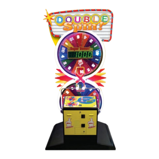
PART DESCRIPTIONS Billboard Upper Feature Wheel Prize LED Inner Disc Lower Inner Disc Upper Right Handle Left Handle Console Lid Ticket Vend L Ticket Vend R Console Cabi Cashbox Door Cabinet Base Please note: Cabinets may vary from that illustrated. -
Page 20: Accessories
ACCESSORIES Confirm that the accessories listed in the table below are present when setting up the product. Accessories marked “Spare” in the note column are consumable items but included as spares. 440-CS0186UK Sticker C Epilepsy Multi (1) DESCRIPTION: OWNER’S MANUAL Part No. - Page 21 DISC INNER UPPER LOWER OUTER SIDE FRONT TOP DB-1023UK For differnt prize values...
-
Page 22: Assembly And Installation
ASSEMBLY AND INSTALLATION • Perform assembly work by following the procedure herein stated. Failure to comply with the instructions can cause electric shock. • Perform assembly as per this manual. Since this is a complex machine, incorrect assembling can cause an electric shock, machine damage and/or improper functioning as per specified performance. -
Page 23: Installing The Cabinet
INSTALLING THE CABINET • Billboard weighs approximately 10kg once assembled. Have at least 2 people during this operation. Working alone could result in personal injuries, etc. • To perform work safely and securely, be sure to prepare a step which is in a safe and stable condition. - Page 24 Fixings required for installation 060-S00500 M5 WSHR SPR PAS (4) 020-000510-0C M5X10 SKT CAP BZP (4) 068-552016 M5 WSHR 20OD FLT PAS (4) 030-000525 M5X25 BLT PAS (4) 060-S00800 M8 WSHR SPR PAS (3) 020-F00850-0Z - M8X50 SKT CSK 0Z (1) 020-F00820-0Z - M8X20 SKT CSK 0Z (2) 068-852216-0B M8 WSHR 22OD FLT BLK (4) DB-0504UK SPCER STANDOFF LONG (4)
- Page 25 6-1-1 ASSEMBLING THE BILLBOARD Locate the parts to assemble the ASSY BILLBOARD within the INST KIT BOX. DB-0501UK - BILLBOARD SURROUND (1) DB-0502UK BILLBOARD COVER (1) DB-0503UK BILLBOARD FRONT FACE (1) Fit the BILLBOARD COVER to the BILLBOARD SURROUND and fix from the rear using (4) M5x25 HEX BLT PAS, (4) M5 SPRING WSHR (4) M5 FLT WSHR and (4) SPACER STAND OFF LONG.
- Page 26 6-1-2 FITTING THE BILLBOARD • Billboard weighs approximately 10kg once assembled. Have at least 2 people during this operation. Working alone could result in personal injuries, etc. • To perform work safely and securely, be sure to prepare a step which is in a safe and stable condition.
- Page 27 Using a step and 2 people, offer the ASSY BILLBOARD up to the cabinet. Connect the harness for the BILLBOARD LEDS making sure that the harness is positioned behind the cabinet frame. Billboard Harness Once the ASSY BILLBOARD is located firmly into position secure it by fitting (2) M8x20 SKT CAP with M8 SPR WSH ans M8 FLT 020-F00820-0Z - M8X20 SKT CSK 0Z (2) 060-S00800 M8 WSHR SPR PAS (2)
- Page 28 Refit the BACK PANEL. M6X25 SKT CAP BLK (8)
- Page 29 6-1-3 FITTING THE SEGMENT SIDES Fit and secure the SEGMENT SIDES over the SPEAKER UNIT and secure using (3) per M6x25 SKT CAP CRM. 020-000625-0C M6X25 SKT CAP CRM (6)
- Page 30 6-1-4 INSTALLING TICKETS This game comes with (2) ticket units installed.. The purpose of these 2 units is so that the game can operate with twice the amount of tickets as a game with only a single unit. The ticket operation is such that when one unit despenses its final ticket the remainder of that win will be paid to the player via the second ticket unit.
- Page 31 Feed the tickets into the ticket holder ensuring that the ticket passes through the guides. Guides Feed the tickets into the ticket holder ensuring that the ticket passes underneath the ticket rollers. Rollers Lower the roller bar and refit the ticket guide, making sure that the guide locks onto the upper bar. Ticket guide Upper bar Lower bar so that the rollers...
- Page 32 Apply power to the cabinet and wait for the machine to initialise. Press the ticket feed button to feed a number of tickets out through the front panel checking for ticket jam in the proccess. Feed button Remove any excess tickets. Repeat the operation to install tickets into the second ticket unit..
-
Page 33: Fixation To Site
FIXATION TO SITE • Make sure that all the adjusters contact the floor. Otherwise the cabinet could move, causing an accident. • Provide a ventilation space at least 15cm wide behind the cabinet. There are ventilation holes on the back of the cabinet. Do not block the ventilation holes. Doing so could trap heat inside resulting in fire. - Page 34 • Provide a ventilation space at least 15cm wide behind the cabinet. There are ventilation holes on the back of the cabinet. Do not block the ventilation holes. Doing so could trap heat inside resulting in fire. It could also result in equipment damage or cause parts to become exhausted prematurely.
-
Page 35: Power Supply And Other Connections
POWER SUPPLY AND OTHER CONNECTIONS • Use the power supply equipped with an earth leakage breaker. Use of power supply without such a breaker could result in fire if there is a current leakage. • Have available a securely grounded indoor ground terminal. Without proper grounding, customers could be electrocuted and product operations might not always be stable. -
Page 36: Turning On The Power
Fully insert the power cord connector on the side opposite the power plug into the AC unit IEC inlet. Insert the power cord plug into the outlet. The power code is laid out indoors. Protect the power cord by attaching wire cover to it. WIRE COVER TURNING ON THE POWER Set the main switch of the AC unit to ON and engage the power. - Page 37 COMPONENTS WHICH CHANGE STATE WHEN POWER IS APPLIED Billboard will illuminate Feature wheels will spin Bonus LED will show Bonus win Audio output from speakers Lighting effect will start Handles will illuminate Coin IN lamp will illuminate...
-
Page 38: Precautions When Moving The Machine
PRECAUTIONS WHEN MOVING THE MACHINE • Always disconnect the power cable before moving the product. If it is moved with the power cable connected, the cable could be damaged, causing fire or electric shock. • To move the unit over the floor, pull in the adjustors and have the casters contact the floor. -
Page 39: Precautions When Moving From Site
PRECAUTIONS WHEN MOVING FROM SITE • When moving the cabinet into and out of buildings, be sure to remove the Billboard Assy. Failure to remove the Billboard Assy may result in personal injury, damage to the cabinet or damage to property. Remove the Billboard and Billboard Plate when transporting the machine in and out of... -
Page 40: Game Description
GAME DESCRIPTION CABINET DESIGN KEY FEATURES • Cabinet has top and bottom wheels above each other • Stepper motor drive for top and bottom wheels • Twin ticket payout devices (Auto switch between devices on ticket empty) • Single Coin entry, 2 digit credit display •... - Page 41 GAME PLAY TIMELINE Coin Insertion Credit will only be given once sufficient coins have been inserted. The Game will not register or otherwise acknowledge any part credits As soon as the Credit Value changes, an AUDIO SFX is played Multiple credits will give repeated AUDIO SFX, although this SFX cannot be interrupted Attract stop If credit changes from zero, all attract lighting and audio will stop immediately Super Bonus display will show current super bonus value.
- Page 42 Strength Meter As the LEFT Lever is pulled, the TOP Edge Lighting will display the “strength” of the Pull. From the bottom of the TOP Wheel, going anti-clockwise, the Edge will change colour to show the amount of travel. Pulling the LEFT Lever to its fullest extent will change the colour of the entire TOP Edge Lighting. As the RIGHT Lever is pulled, the BOTTOM Edge Lighting will display the “strength”...
- Page 43 Wheel Spin Stop As a Wheel stops, there is a STOP audio SFX to indicate the event. The Edge lighting will sweep WHITE towards the Win-line, leaving the Edge lighting OFF behind it The Number resting in the Win-line will be LIT The Win-line will be LIT Once the TOP Wheel stops, the Numeric value on the Win Line will be shown on the Super Bonus display positions 1 &...
-
Page 44: Explanation Of Test And Data Display
EXPLANATION OF TEST AND DATA DISPLAY Perform tests and data checks periodically by manipulating the TEST Button and SERVICE Button in the cabinet. Follow the instructions in this chapter to conduct checks when the game machine is first installed, when money is being collected, or when the game machine does not operate properly. -
Page 45: Switch Unit And Coin Meter
9-1 SWITCH UNIT AND COIN METER. The SWITCH UNIT and COUNTERS are housed within the COINTOWER. To access these controls you will need to open the COIN door, the switches and counters can be found directly on the rear face of the Tower. Channel 1 Status LED Credit PCB... - Page 46 TEST MENU Press the TEST button to open the TEST MENU. The following options are available from the TEST MENU. SYSTEM INFO General Information and version numbers for software and hardware. LIGHTING TEST Test functions for the lighting of the cabinet DISPLAY TEST Test functions for the 7 segment LED and Starburst displays INPUT TEST...
- Page 47 LIGHTING TEST Select LIGHTING TEST from the TEST MENU to display the LIGHTING TEST menu. TEST MENU 2.LIGHTING TEST The LIGHTING TEST is used to test the functionality of the lights on the cabinet. To implement the test, select a lighting test and press the Test button to turn on/off or cycle through the light(s). ALL LEDS This will turn all lighting features for the cabinet on/off.
- Page 48 LED STEP SERIAL This test will cycle through (in order) the LEDs around the top then bottom wheel. LIGHTING TEST LED STEP SERIAL Pressing the TEST button will cycle anticlockwise around the top and bottom wheel. LED STEP SERIAL SER TOP:00 RED LED STEP SERIAL SER TOP:00 GREEN Press the SERVICE button to stop the test and return to the LIGHTING TEST menu.
- Page 49 DISPLAY TEST Select DISPLAY TEST from the TEST MENU to display the DISPLAY TEST menu. TEST MENU 3.DISPLAY TEST The DISPLAY TEST is used to test the numeric displays. The first display is on the control panel and is used to show credits available.
- Page 50 INPUT TEST Select INPUT TEST from the TEST MENU to display the INPUT TEST menu. TEST MENU 4.INPUT TEST The INPUT TEST contains test functions for the cabinet input devices, such as switches, buttons and levers. LEVER INPUTS This test shows the input signals for the levers. Moving either the left or right will display the current input signal. LEVER L 0175 LEVER R 0000 SWITCH INPUTS...
- Page 51 OUTPUT TEST Select OUTPUT TEST from the TEST MENU to display the OUTPUT TEST menu. TEST MENU 5.OUTPUT TEST This test is used to check all configured outputs from the IO board. This includes physical meters, ticket vends and stepper motors. METER OUTPUTS This test will send a pulse to the game and ticket meters and increase their values by 1 unit.
- Page 52 CALIBRATION Select CALIBRATION from the TEST MENU to display the CALIBRATION menu. TEST MENU 6.CALIBRATION This test is used to calibrate the levers and set the offset levels for the top and bottom wheels. CALIBRATE LEVERS CALIBRATION This test will allow for the levers to be calibrated and ensure reliable game CALIBRATE LEVERS play.
- Page 53 AUDIO SETTINGS Select AUDIO SETTINGS from the TEST MENU to display the AUDIO SETTINGS menu. TEST MENU 7.AUDIO SETTINGS This test is used to turn on/off the sound during attract, when the game has zero credit, and test the speakers performance.
- Page 54 GAME SETTINGS Select GAME SETTINGS from the Test Menu screen to display the GAME SETTINGS menu. TEST MENU 8.GAME SETTINGS This test is used to change percentage payout, cost of play, ticket values and Super Bonus settings. This menu is set out differently to previous menus. When entering GAME SETTINGS the option to change settings is display immediately.
- Page 55 SUPERBONUS INC Options available: 0.1, 0.25, 0.5, 1, 2, 3, 4, 5, 10 SUPERBONUS INC SETTING: 1 Only used when the SUPERBONUS TYPE is set to INCRMNT. This is the value Super Bonus increments after each game. UPERBONUS FREQ Options available: LOW, NORMAL and HIGH SUPERBONUS FREQ SETTING: NORMAL This function modifies the Super Bonus drop frequency by allocating more tickets to the Super Bonus each game.
- Page 56 BOOKKEEPING Select BOOKKEEPING from the Test Mode to display the BOOKKEEPING menu. TEST MENU 9.BOOKKEEPING This test is used to review statistical data from the system, and also clear all bookkeeping, tickets owed and unused service credits. Press the SERVICE button to view the next BOOKKEEPING screen. SCREEN 1 CREDITS Total number of COIN credits entered...
- Page 57 CLEAR METERS This option allows you to clear all bookkeeping data. WARNING – ONCE DELETED THIS INFORMATION CAN NOT BE RESTORED CLEAR METERS Press the TEST button to show the clear message. CLEAR METERS ARE YOU SURE? Y Press the SERVICE button to change between N and Y. Press the TEST button to confirm your selection.
- Page 58 SET DATE/TIME Select SET DATE/TIME from the Test Menu screen to enter the SET DATE/TIME menu. TEST MENU 10.SET DATE/TIME This screen is used to set the time and date of the system. The current date and time setting for the system is always displayed at the top of the screen.
-
Page 59: Controller Unit(S)
CONTROLLER UNIT(S) • When working with the product, be sure to turn the power off. Working with the power on may cause an electric shock or short circuit. • Be careful not to damage the wires. Damaged wires may cause an electric shock, short circuit or present a risk of fire. -
Page 60: Ajusting/Changing The Pot
Be sure to remove the power before attempting service or repair to the controller. Failure to remove power may result in component damage or shock hazzard. In cases where the Handle operability is poor and/or the adjustment or replacement of the POT is required. It may be nescessary to replace either the COIL or the POT from within the controller depending on the fault condition. - Page 61 Locate the potentiometer. Potentiometer for the right hand controller Locate and remove the (2) Hex Bolts which secure the Potentiometer Bkt to the controller mech. Hex Bolt Carefully remove the potentiometer and brkt taking care not to damage any wires.. Hex Bolt Pot and Gear assy...
- Page 62 REPLACEMENT PROCEDURE This procedure requires the following tools: Phillips screwdriver for the M4 screws, 1.5 mm hexagonal wrench, 11-12 mm monkey wrench, nipper, cutter, wire stripper, soldering iron, industrial dryer and heat-shrinkable tube. Using a soldering iron - desolder the 3 wires which are connected to the pot. Make note of the position of the wires before desoldering.
- Page 63 Refit the pot to the VR bracket keeping the pot in the same orientation as when initially removed. VR Bracket Fit the Gear to the pot shaft taking care not to overtighted the fixing as this could damage the thread inside the gear.
-
Page 64: Greasing
10-2 GREASING • Be sure to use the designated grease. Using undesignated grease can cause parts damage. • Do not apply grease to locations other than as specified. Doing so may create a risk of operational problems and deterioration of parts. •... -
Page 65: Feature Wheels Upr & Lwr
FEATURE WHEELS UPR & LWR The two main features of this game are the spinning discs or feature wheels. Each time a handle is pulled, the corresponding wheel will rotate at a speed chosen by the player when pulling down on each handle. - Page 66 Carefully flip the disc onto the reverse side and remove the inner disc plate. Inner Disc Plate Remove the (9) plastice rivets from various locations around the disc. Fit the new denomination disc by following the instructions in reverse order. (The denomination disc can only be fitted in one position, do not try to force application.)
-
Page 67: Coin Handling
COIN HANDLING Handling the Coin Jam If the coin is not rejected when the REJECT button is pressed, open the coin chute door and open the selector gate. After removing the jammed coin, put a normal coin in and check to see that the selector correctly functions. 12-1 CLEANING THE COIN SELECTOR ●... - Page 68 CLEANING THE COIN SELECTOR (MECHANICAL). Remove and clean smears by using a soft cloth dipped in water or diluted chemical detergent and then squeezed dry. Remove the CRADLE.. When removing the retaining ring (E ring) be very careful so as not to bend the rotary shaft.
- Page 69 CLEANING THE COIN SELECTOR (SR3) <continued> Remove and clean smears by using a damp soft cloth dipped in water. DO NOT use any diluted chemical detergent or cleansing agent as this will impair the workings of the component. GATE Open the reject gate to gain access to the rundown path.
-
Page 70: Fault Finding
12-2 FAULT FINDING Fault Finding The following information is presented for customers’ guidance in rectifying a fault but does not cover all possible causes. All acceptors with electronic faults should be returned to an approved service centre for repair. SYMPTOM INVESTIGATE POSSIBLE CAUSE Poor Contact... -
Page 71: Adjusting The Price Of Play (Excel)
12-3 ADJUSTING THE PRICE OF PLAY (EXCEL) ● The price of play is determined by the configuration of switches located on either an EXCEL board or VTS board. The type of board used is determined by product location. Switch settings for both types of board remain the same. This product comes equipped with a Crane NRI Coin Acceptor. - Page 72 REGIONAL AND ACCEPTOR SETTINGS (SW3)
- Page 73 STERLING PRICE OF PLAY SETTINGS (SW1)
- Page 74 EURO PRICE OF PLAY SETTINGS (SW1)
-
Page 75: Lamps And Lighting
LAMPS AND LIGHTING • When working with the product, be sure to turn the power off. Working with the power on may cause an electric shock or short circuit. • Be sure to use lamps of the designated rating. Using lamps of undesignated rating can cause a fire or malfunctioning. -
Page 76: Replacing The Led (Wht) Upper/Lower Disc
13-2 REPLACING THE LED (WHT) UPPER/LOWER DISC TAKE CARE WHEN ACCESSING THE INTEGRAL PARTS OF THE MACHINE. MAKE SURE POWER IS REMOVED BEFORE SERVICING. ONLY TOUCH PARTS WHICH ARE OUTLINED IN THE INSTRUCTIONS BELOW. FAILURE TO OBSERVE THIS CAUTION MAY RESULT IN INJURY OR COMPONENT DAMAGE. REMOVING THE WHT LED ARRAY TURN THE POWER OFF. - Page 77 Carefully lower the disc from the top whilst keeping the bottom hinged inplace. Rest the disc on both handles so that it is possible to disconnect the LED harness.. Once the LED harness has been disconnected the disc can be removed. LED Harness Using a Philips screwdriver, remove the (4) M4 machine screws from the centre of the disc.
- Page 78 At the rear of the cabinet - remove the Pozidrive self tap fixings (5) from the rear cover bracket and remove. Remove the Self tap fixings (5) Locate the harness for the appropriate LED array and disconnect it from the Main harness. LED Harness Once disconnected - push the connector through the hole out into the disc housing.
- Page 79 FITTING THE WHT LED ARRAY When fitting the replacement WHT LED array (DB-60030UK) make sure the component is intact and free from damage. Peel away the protective backing and adhere in the same location as the previous LED PCB. Follow steps 8 and 9 in reverse order. Power on the machine - the machine will try to initialise but without the Upper Disc fitted will fail to do sa nad time out after 30 seconds.
-
Page 80: Replacing The Led (Rgb) Upper/Lower Disc
13-3 REPLACING THE LED (RGB) UPPER/LOWER DISC At the rear of the cabinet - remove the Pozidrive self tap fixings (5) from the rear cover bracket and remove. Remove the Self tap fixings (5) Locate the harness for the appropriate LED array and disconnect it from the PCB. RGB LED The RGB LED PCB has dedicated INPUT and OUTPUT connectors. - Page 81 Carefully pull out the plastic rivet to release the RGB LED from the Disc housing.. Plastic Rivet Disconnect the connectors either side of the REG LED PCB and remove. IMPORTANT: Make a note of the orientation of the RGB LED PCB before removal. Fit the replacement RGB LED PCB to the Disc Housing making sure the alignment of the LEDs are correct with the holes and secure with the Push Rivet..
-
Page 82: Periodic Inspection
PERIODIC INSPECTION The items listed below require periodic check and maintenance to retain the performance of this machine and to ensure safe business operation. When handling the controller, the player will be in direct contact with it. In order to always allow the player to enjoy the game, be sure to clean it regularly. - Page 83 Cleaning the Cabinet Surfaces When the cabinet surfaces are badly soiled, remove stains with a soft cloth dipped in water or diluted with a chemical detergent and squeezed dry. To avoid damaging surface finish, do not use such solvents as thinner, benzine, etc.
-
Page 84: Troubleshooting
TROUBLESHOOTING 11-1 TROUBLESHOOTING (WHEN NO ERROR MESSAGE IS SHOWN) • In order to prevent electric shock and short circuit, be sure to turn power off before performing work. • Be careful so as not to damage wirings. Damaged wiring can cause electric shock or short circuit. - Page 85 • This work should be performed by site maintenance personnel or other skilled professionals. Worl performed by non-techical personnel may cause a severe accident such as electric shock. If there are no sire maintenance personnel or other skilled professionals available, turn the power off immediately and contact the office given in this manual or from the point of purchase.
- Page 86 PROBLEM CAUSE COUNTERMEASURE With main switch ON there Power is not supplied Insert power lead all the way into is no activation outlet Supply voltage is not correct Make sure that supply voltage is correct Circuit protector activated Reset circuit protector/replace fuse There is sound and lighting LED signal connector is not...
-
Page 87: Game Board
GAME BOARD ● When working with the product, be sure to turn the power off. Working with the power on may cause an electric shock or short circuit. ● Be careful not to damage the wires. Damaged wires may cause an electric shock, short circuit or present a risk of fire. - Page 88 RINGWIDE. Failure to observe these instructions may cause an overheating and fire. • Always follow the usage conditions from SEGA as well as the usage conditions for the cabinet you are using for RED ONE (UN COCH). Failure to do so may cause an overheating and fire.
- Page 89 16-2 GAME BOARD - LOCATION & REMOVAL ● When returning the game board after making repairs or replacements, make sure that there are no errors in the connection of connectors. Erroneous connections can lead to electrical shock, short circuits or fires. ●...
- Page 90 16-3 GAME BOARD - INTRODUCTION The RED-M board is an arcade game controller capable of driving two simple cabinets at once. It contains a powerful ARM processor running at 100MHz and many peripherals, including: • SD card for game software and data logging •...
- Page 91 16-4 GAME BOARD - PARTS DETAIL LAYOUT Stepper 16 Scanned Motor Drives Digital Inputs 6 Way DIP Switch 2 Meter Outputs 14 “Direct to processor” Digital Inputs 16 x 2 LCD display with backlight Service Board Con. Serially Driven LED s Output 4 Jackpot 7seg digits + LED / 1A LSD...
- Page 92 • Do not connect components to any connector that are not designated by SEGA. Connecting unspecified components could cause an accident such as an electric shock or fire.
- Page 93 7 - Segment LED Display LOCATION TYPE 16W JST RA TYPE Function Function A Credit UNITS A Credit TENS A SEG a A SEG b A SEG c A SEG d A SEG e A SEG f A SEG g A SEG dp A JP UNIT A JP TENS...
- Page 94 Ethernet LOCATION TYPE RJ45 Function TD + TD - RD + RD - C_GND Power LOCATION TYPE 4W JST VH Function Counters / Meters LOCATION TYPE 6W JST NH Function +12V Ticket #2 Meter Meter 2 Ticket #3 Meter Meter 3 Spare Open Collector Spare_2 Spare Open Collector...
- Page 95 LCD Display LOCATION TYPE 20W JST RA TYPE Function Function LED + LED - 7 - Segment LED Display LOCATION TYPE 16W JST RA TYPE Function Function B Credit UNITS B Credit TENS B SEG a B SEG b B SEG c B SEG d B SEG e B SEG f...
- Page 96 NOT USED LOCATION TYPE SD CARD READER FAT16 LOCATION TYPE 4W JST VH Function DATA IN (MOSI) CLK (SCLK) DATA OUT (MOSO) DIGITAL INPUTS MUX0-15 LOCATION TYPE 26W JST RA TYPE Function Function START SW MUX0 MUX1 UP SW RIGHT SW MUX2 MUX3 DOWN SW...
- Page 97 BOOT LOADER - DEV PURPOSES ONLY LOCATION TYPE 5W SIL HDR DIRECT DIGITAL INPUTS LOCATION TYPE 26W JST RA TYPE Function Function COIN IN 1 DID0 DID1 NOT USED TICKET COUNT DID2 DID3 TICKET COUNT WHEEL SW T DID4 DID5 NOT USED WHEEL SW B DID6...
- Page 98 ANALOGUE INPUTS LOCATION TYPE 26W JST RA TYPE Function Function L/H Handle AID 0 AID 1 R/H Handle AID 2 AID 3 AID 4 AID 5 Audio Volume AID 6 AID 7 LOCATION TYPE 6W JST PH K S Function RGB Latch RGB Data RGB CLK...
- Page 99 7 - Segment LED Display LOCATION TYPE 16W JST RA TYPE Function Function Solenoid #2 DLS_7 External Prize Vend #5 DLS_8 External BOT Wheel C DLS_9 External Ticket Vend #3 DLS_10 DHS_10 Ticket Vend #3 BOT Wheel D DLS_11 BOT Wheel L DLS_12 Ticket Vend #4 DLS_13...
- Page 100 SERVICE LOCATION TYPE 9W JST NH Function VOLUME CONT +12V COIN IN MOTOR PORT A LOCATION TYPE 6W JST VH - VNR-6N Function STEPPER 0 STEPPER 1 STEPPER 2 STEPPER 3 MOTOR PORT B LOCATION TYPE 6W JST VH - VNR-6N Function TOP DC DRIVE STEPPER 4...
- Page 101 VEND OUTPUTS LOCATION TYPE 16W JST RA TYPE Function Function Solenoid #2 DLS_7 External Prize Vend #5 DLS_8 External BOT Wheel C DLS_9 External Ticket Vend #3 DLS_10 DHS_10 Ticket Vend #3 BOT Wheel D DLS_11 BOT Wheel L DLS_12 Ticket Vend #4 DLS_13 DHS_13...
- Page 102 COMMS RS232 LOCATION TYPE 9W D Type Female Function COMMS RS232 LOCATION TYPE 5W JST NH Function CAN PORT LOCATION TYPE 3W JST NH Function CAN1_H CAN1_L...
- Page 103 CAN PORT LOCATION TYPE 9W D Type Female Function CAN1_L CAN1_H AUDIO BRIDGE LOCATION TYPE 3W JST NH Function BRIDGE NOT USED BRIDGE AUDIO LOCATION TYPE 4W JST NH Function SPKR L Common SPKR R Common...
- Page 104 DIP SWITCH LOCATION TYPE 6W DIP SW Usage differs depending on game software. Set accordingly to the instructions given in this service manual under the section of TEST and DISPLAY DATA - DIP SWITCH SETTINGS The factory settings when a game board (RedOne) is purchased as a stand alone unit No.
- Page 105 16-5 REPLACING THE BUTTON BATTERY • Make sure you do not damage the printed board and wires. Such damage can lead to electric shock, short circuit and fire hazard. • To prevent overheating, explosion, or fire: • Do not recharge, disassemble, heat, incinerate, or short the battery. •...
-
Page 106: Design-Related Parts
DESIGN-RELATED PARTS For the warning display stickers, refer to Section 1. -
Page 107: Parts List
PARTS LIST TOP ASSY DOUBLE SPIN BOM STRUCTURE... - Page 108 1 ASSY TOP DOUBLE SPIN (DB-0000UK) (D-1/1) ITEM NO PART NUMBER DESCRIPTION DB-1000UK ASSY MAIN CABI 421-7988-91UK STICKER SERIAL NUMBER UK 440-WS0010UK LABEL WARNING HI-VOLTAGE 440-WS0030UK LABEL WARNING CAUTION LB1046 LABEL TESTED FOR ELEC. SAFETY LB1130 LABEL WEEE WHEELIE BIN...
- Page 109 2 ASSY BILLBOARD (DB-0500UK) (D-1/1) 201 202 203 ITEM NO PART NUMBER DESCRIPTION ***1 DB-0501UK BILLBOARD SURROUND ***2 DB-0502UK BILLBOARD COVER ***3 DB-0503UK BILLBOARD FRONT FACE ***4 DB-0504UK SPACER STANDOFF LONG ***5 DB-0505XUK BRKT MOUNT BILLBOARD ***6 280-6696UK 5.5-20X6.3 WSHR SPCL AL ***101 ***102 DB-6002UK...
- Page 110 3 ASSY MAIN CABINET (DB-1000UK) (D-1/3) 206 207 222 223...
- Page 111 3 ASSY MAIN CABINET (DB-1000UK) (D-2/3) ITEM NO PART NUMBER DESCRIPTION DB-1100XUK ASSY CONTROL BOX DB-1200UK ASSY DISC UPPER DB-1300UK ASSY DISC LOWER DB-1450UK ASSY MOTOR STEPPER MKII DB-1700UK ASSY AC SWITCH **10 DB-1001XUK FRAME MAIN **11 DB-1002UK DISC INNER SUPPORT **12 DB-1003UK WIN WINDOW...
- Page 112 3 ASSY MAIN CABINET (DB-1000UK) (D-3/3) ITEM PART NUMBER DESCRIPTION **216 029-B00625-0B M6X25 SKT BH BLK **217 029-B00412-0B M4X12 SKT BH BLK **218 068-441616-0B M4 WSHR 16OD FLT BLK **219 020-000820-0Z M8X20 SKT CAP OZ **220 050-F00400 M4 NUT FLG SER PAS **221 060-S00600 M6 WSHR SPR PAS...
- Page 113 4 ASSY CONSOLE (DB-1100XUK) (D-1/2)
- Page 114 4 ASSY CONSOLE (DB-1100XUK) (D-2/2) ITEM NO PART NUMBER DESCRIPTION ***1 DB-1101XUK CONSOLE ***2 DB-1102UK CONSOLE LID ***3 DB-1120XUK ASSY FRONT CONSOLE ***4 DB-1150UK ASSY DIAGNOSTICS CONSOLE ***5 DB-4100UK ASSY MAIN BOARD ***6 DB-1105UK HOLDER TICKET L ***7 DB-1106UK HOLDER TICKET R ***8 DB-1108UK CAP EXTENDED...
- Page 115 5 ASSY FRONT CONSOLE (DB-1120XUK) (D-1/1) ITEM NO PART NUMBER DESCRIPTION ****1 DB-1121XUK FRONT CONSOLE ****2 DB-1122UK PLATE DBA BLANKING ****3 DB-1123UK TNG LID ****101 220-0001-01UK TICKET VEND UNIT TD-963CR ****102 220-5610-01 COIN MECH SR3 ****103 220-5575UK LOCK (J9117) KEY TO LIKE 22MM W CAM ****104 220-5574UK LOCK KEYED DIFFERENT 7087-10...
- Page 116 6 ASSY DIAGNOSTICS CONSOLE (DB-1150UK) (D-1/1) ITEM NO PART NUMBER DESCRIPTION ****1 DB-1151UK BRKT DIAGNOSTICS ****101 838-14548-01AUK SW & VOL CTL BD ****102 EP1380-01 EXCEL CREDIT BOARD ****103 220-5643UK 12V COIN METER ****105 EP1429 LCD MDL 2X16 PC1602LRS ****106 OS1098 CRIMP BELL END SMALL ****107 280-L00706-PM...
- Page 117 7 ASSY DISC UPPER (DB-1200UK) (D-1/1) ITEM NO PART NUMBER DESCRIPTION ***1 DB-1201UK DISC CASE ***2 DB-1212UK COVER TANGENTIAL LED BD MKII ***101 838-0025UK PCBA-RGB SERIAL ***102 DB-6001UK ASSY LED WHITE RGD 40MM ***201 012-P03506-F N6X1/4" S/TAP FLG PAS ***202 068-441616 M4 WSHR 16OD FLT PAS ***303...
- Page 118 8 ASSY DISC LOWER (DB-1300UK) (D-1/1) ITEM NO PART NUMBER DESCRIPTION ***1 DB-1201UK DISC CASE ***2 DB-1212UK COVER TANGENTIAL LED BD MKII ***101 838-0025UK PCBA-RGB SERIAL ***102 DB-6001UK ASSY LED WHITE RGD 40MM ***104 OS1249 P CLIP 6.5MM ***105 OS1195 RIVET SNAP MOSS SR1811 ***201 012-P03506-F...
- Page 119 9 ASSY MOTOR STEPPER (DB-1450UK) (D-1/1) ITEM NO PART NUMBER DESCRIPTION ***1 DB-1451UK BRKT MTG MOTOR ***2 DB-1452UK COUPLER MOTOR SHAFT ***3 DB-1453UK COUPLER MOTOR PLATE ***4 DB-1454UK BRKT MTG MAG SWITCH ***101 350-012-208UK MOTOR DC 12V W/GB X0229760 ***102 EP1406 STOP SWITCH CHERRY MP201801 ***103...
- Page 120 10 ASSY AC SWITCH (DB-1700UK) (D-1/1 ) ITEM NO PART NUMBER DESCRIPTION ***1 DB-1701UK MAINS IN PLATE ***101 EP1381 FILTER IEC & SW 6A ROXBURGH ***201 000-F00310 M3X10 MSCR CSK PAS ***301 DB-60044UK WH AC IN...
- Page 121 11 ASSY AC MAIN BD (DB-4100UK) (D-1/1 ) ITEM NO PART NUMBER DESCRIPTION ****1 DB-4101UK WOODEN BASE MAIN BD ****101 838-0023UK PCBA - RED ONE ****102 280-L00640-WX STANDOFF 6MM 4 HOLE WOOD XL ****103 280-A01264-WX ROUTER TWIST D12 SO6.4 WOOD X ****104 280-A02064-WX ROUTER TWIST D20 SO6.4 WOOD X...
- Page 122 M8 WSHR 22OD FLT BLK **204 060-S00800 M8 WSHR SPR PAS **205 020-000625-0C M6X25 SKT CAP CRM **401 420-0017UK MANUAL DOUBLE SPIN **402 OS1019 SELF SEAL BAG 9X12.3/4 **403 DOC-XXX DECLARATION OF CONFORMITY DB **404 PK0489 BOX INST KIT DB STD...
-
Page 123: Wire Colour Code Table
WIRE COLOUR CODE TABLE The DC power wire color for this product is different from previous SEGA titles. Working from the previous wire colors will create a high risk of fire. The color codes for the wires used in the diagrams in the following chapter are as follows. -
Page 124: Wiring Diagrams
(D-1/5) WIRING DIAGRAMS... - Page 125 (D-2/5)...
- Page 126 (D-3/5)...
- Page 127 (D-4/5)...
- Page 128 (D-5/5)...
Need help?
Do you have a question about the Double Spin and is the answer not in the manual?
Questions and answers