
Related Manuals for AUMA SG Series


Summary of Contents for AUMA SG Series
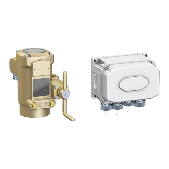
- Page 1 Part-turn actuators SG 04.2 SG 10.2 with actuator controls MEC 03.1 Marine version Operation instructions Assembly and commissioning...
-
Page 2: Table Of Contents
Pass on instructions to any subsequent user or owner of the product. Target group: This document contains information for assembly, commissioning and maintenance staff. Reference documents: Reference documents can be downloaded from the Internet (www.auma.com) or ordered directly from AUMA (refer to <Addresses>). Table of contents Page Safety instructions......................... - Page 3 10.1. Mechanical position indicator 10.2. Indication lights on local controls of MEC 03.1 Signals (output signals)......................11.1. Status signals (output signals) AUMA CDT software (accessories)..................Corrective action........................13.1. Fault indications and warning indications 13.2. Fuses 13.2.1. Fuses within the actuator controls Servicing and maintenance....................
-
Page 4: Safety Instructions
Any device modification requires prior written consent of the manufacturer. 1.2. Range of application AUMA part-turn actuators are designed for the operation of valves, e.g. butterfly valves and ball valves. Other applications require explicit (written) confirmation by the manufacturer. The following applications are not permitted, e.g.:... -
Page 5: Warnings And Notes
SG 04.2 SG 10.2 with actuator controls MEC 03.1 Safety instructions Buried service Continuous submersion (observe enclosure protection) Potentially explosive atmospheres Radiation exposed areas in nuclear power plants No liability can be assumed for inappropriate or unintended use. Observance of these operation instructions is considered as part of the device's designated use. -
Page 6: Short Description
AUMA Cloud interactive platform for efficient maintenance of AUMA actuators at moderate cost. The AUMA Cloud collects all device data of all actuators within one site and provides a clear overview at a glance. Detailed analysis provides valuable information on potential maintenance requirements. -
Page 7: Name Plate
SG 04.2 SG 10.2 with actuator controls MEC 03.1 Name plate Name plate Figure 2: Arrangement of name plates Actuator name plate Actuator controls name plate Actuator name plate Figure 3: Actuator name plate (example) (= manufacturer logo); (= CE mark) Name of manufacturer Address of manufacturer Type designation... - Page 8 Positions 3+4: Year of manufacture = 2020 NS12345 Internal number for unambiguous product identification When registered as authorised user, you may use our AUMA Assistant App to scan Data Matrix code the Data Matrix code and directly access the order-related product documents without having to enter order number or serial number.
-
Page 9: Transport And Storage
SG 04.2 SG 10.2 with actuator controls MEC 03.1 Transport and storage Transport and storage 4.1. Transport For transport to place of installation, use sturdy packaging. Hovering load! Risk of death or serious injury. Do NOT stand below hovering load. Attach ropes or hooks for the purpose of lifting by hoist only to housing and NOT to handwheel. -
Page 10: Assembly
SG 04.2 SG 10.2 Assembly with actuator controls MEC 03.1 Assembly 5.1. Mounting position The product described in this document can be operated without restriction in any mounting position. 5.2. Actuator: mount to valve The actuator is mounted to the valve using a coupling. 5.2.1. - Page 11 Valve shaft Grub screw Clamping washer and screw with curved spring lock washer Figure 9: Mounting positions for coupling Table 2: Mounting position of the coupling within fitting dimensions according to AUMA definition Dimensions SG 04.2 SG 05.2 SG 07.2 SG 10.2...
- Page 12 SG 04.2 SG 10.2 Assembly with actuator controls MEC 03.1 Fit actuator. If required, slightly turn actuator until splines of coupling engage. Figure 10: Ensure that the spigot (if provided) fits uniformly in the recess and that the flanges Information are in complete contact.
-
Page 13: Electrical Connection
It can plan also be requested from AUMA (state order number, refer to name plate) or downloaded directly from the Internet (http://www.auma.com). The actuators are suitable for use in TN and TT networks with directly earthed star Permissible networks point. -
Page 14: Overview Of Connections And Wiring
SG 04.2 SG 10.2 Electrical connection with actuator controls MEC 03.1 6.2. Overview of connections and wiring Figure 11: Connections and wiring for MEC 03.1 with actuator Symbols: pins; sockets Sockets: [XG1] Power supply (mains voltage) [XG2] Control and signalling [XG3] Motor control [XG4] Signals to and from the actuator [XA1] Motor... -
Page 15: Connection Via Bayonet Connector
SG 04.2 SG 10.2 with actuator controls MEC 03.1 Electrical connection 6.3. Connection via bayonet connector Figure 12: Connections at MEC 03.1 (standard) [XG1] 5 contacts, VDE compliant socket, for power plug (power supply) [XG2] 19 contacts, socket for signal connector [XG3] 5 contacts, socket for power plug to actuator [XG4] 17 contacts, socket for signal connector to the actuator Figure 13: Connections to MEC 03.1 (compatible with MEC 02.1) - Page 16 For further data such as terminal cross sections, cable diameters and tools e.g. crimping pliers refer to separate Technical data “ITT Cannon connector” (AUMA document number: Y007.274) Hazardous voltage at open connector (capacitor discharge)! Risk of electric shock.
-
Page 17: External Earth Connection
SG 04.2 SG 10.2 with actuator controls MEC 03.1 Electrical connection 6.4. External earth connection Figure 15: Earth connection at MEC 03.1 and actuator External earth connection (U-bracket) for connection to equipotential compensation. Application Hazardous voltage due to insulating impact of powder coating! Risk of electric shock. -
Page 18: Accessories For Electrical Connection
SG 04.2 SG 10.2 Electrical connection with actuator controls MEC 03.1 6.5. Accessories for electrical connection 6.5.1. Local controls Figure 16: MEC 03.1 actuator controls with local controls (option) During motor operation, the actuator may be operated from LOCAL via the push buttons of local controls. -
Page 19: Commissioning
SG 04.2 SG 10.2 with actuator controls MEC 03.1 Commissioning Commissioning 7.1. Mechanical end stop setting The mechanical end stops in actuator limit the swing angle. They protect the valve during motor operation and serve the purpose as travel limitation for manual operation via crank handle or handwheel. -
Page 20: End Stop Open: Set
SG 04.2 SG 10.2 Commissioning with actuator controls MEC 03.1 If the valve end position is not reached: Slightly turn setting screw [4] counterclockwise until valve end position CLOSED can be correctly set. Turning the setting screw [4] clockwise decreases the swing angle. Turning the setting screw [4] counterclockwise increases the swing angle. -
Page 21: Switch Compartment: Open/Close
SG 04.2 SG 10.2 with actuator controls MEC 03.1 Commissioning 7.2. Switch compartment: open/close Figure 18: The following sub-assemblies are located within the switch compartment: End position detection RWG electronic position transmitter (option) Mechanical position indicator The switch compartment must be opened to perform the setting of these sub-assemblies. -
Page 22: End Position Detection: Verify/Set
SG 04.2 SG 10.2 Commissioning with actuator controls MEC 03.1 7.3. End position detection: verify/set Figure 19: Verify/set end position detection using LEDs Screws for setting CLOSED Setting disc Screw [L1] Green LED, signals end position OPEN [L2] Yellow LED, signals end position CLOSED The end position detection signals that end positions OPEN and CLOSED have been reached.The “End position OPEN/CLOSED reached”... - Page 23 SG 04.2 SG 10.2 with actuator controls MEC 03.1 Commissioning Set switching point (yellow LED is brightly illuminated) by turning clockwise. Figure 20: If the LED is only dimly illuminated, the switching point has not yet been reached. Once you have turned too far, the yellow LED goes out again. The setting disc should be positioned in the middle between illumination and going out of the yellow LED.
-
Page 24: Setting For Counterclockwise Closing
SG 04.2 SG 10.2 Commissioning with actuator controls MEC 03.1 7.3.2. Setting for counterclockwise closing The following description is only valid for “counterclockwise closing”, i.e. driven shaft turns counterclockwise to close the valve. Designation in the wiring diagram: TPC ... AIB ... for “clockwise” Switch on the power supply. -
Page 25: Rwg Electronic Position Transmitter
SG 04.2 SG 10.2 with actuator controls MEC 03.1 Commissioning 7.4. RWG electronic position transmitter RWG electronic position transmitter records the valve position. On the basis of the actual position value measured by the potentiometer (travel sensor), it generates a current signal between 4 20 mA. -
Page 26: Mechanical Position Indicator: Set
SG 04.2 SG 10.2 Commissioning with actuator controls MEC 03.1 Turn trimmer potentiometer [2] clockwise until output current starts to increase. Turn back trimmer potentiometer [2] until a value of approx. 4.1 mA has been reached. This ensures that the signal remains above the dead and live zero point. Move valve in direction OPEN to the mechanical end stop. - Page 27 SG 04.2 SG 10.2 with actuator controls MEC 03.1 Commissioning Further information on indication: ⇨ page 37, Mechanical position indicator...
-
Page 28: Basic Settings For The Actuator Controls
Setting the operating time To perform basic settings, proceed as follows: via switches (directly at the device); For switch setting, open actuator controls cover. via AUMA CDT software (with computer/notebook, tablet); ⇨ page 6, Software (Software versions can be downloaded from www.auma.com) -
Page 29: Setting Via Hardware (Switches) Or Via Software
8.2. Setting via hardware (switches) or via software The switch [S5] position determines whether the hardware settings (switches) or the software settings (via AUMA CDT software) are currently active. Figure 27: Switch [S5] = Hardware/software mode Table 7: Switch [S5] functions Hardware mode (factory setting on delivery) Settings of switches [S2] through [S4] and [S6] through [S10] are valid. -
Page 30: Torque Switching: Set
[S10] End position CLOSED Table 8: Function of switches [S9], [S10] Limit seating, sliding switch at white dot Torque seating Setting via software parameters (AUMA CDT) Condition: Switch [S5] is in position ON (software mode). Setting parameters Customer settings Type of seating... -
Page 31: Operating Time: Set
Switch steps Tripping torques [Nm] SG 04.2 SG 05.2 SG 07.2 SG 10.2 Setting via software parameters (AUMA CDT) Condition: Switch [S5] is in position ON (software mode). Setting parameters Customer settings Torque switching Tripping torque CLOSE (S7) Tripping torque OPEN (S6) - Page 32 Motor is operating in stepping mode Setting via software parameters (AUMA CDT) Motor speed and thus actuator operating time can be modified by means of the software parameters described below. Contrary to operating time setting using switch...
- Page 33 SG 04.2 SG 10.2 with actuator controls MEC 03.1 Basic settings for the actuator controls Motor speed Speed LOCAL Speed REMOTE Speed I/O interface Description of parameters: Output speed for operation via local controls (operation mode Local); Setting range: Speed LOCAL linear between 0 100 % of max.
-
Page 34: Operation And Control Of Actuator
SG 04.2 SG 10.2 Operation and control of actuator with actuator controls MEC 03.1 Operation and control of actuator 9.1. Manual operation For purposes of setting and commissioning, in case of motor or power failure, the actuator may be operated manually. The handwheel does not rotate during motor operation. -
Page 35: Motor Operation
SG 04.2 SG 10.2 with actuator controls MEC 03.1 Operation and control of actuator 9.2. Motor operation 9.2.1. Actuator control from Remote For operation commands from Remote, up to four digital inputs within the MEC 03.1 actuator controls are available. Wiring diagram designations: REMOTE OPEN , STOP, REMOTE CLOSE... - Page 36 SG 04.2 SG 10.2 Operation and control of actuator with actuator controls MEC 03.1 Figure 33: Local controls Push button OPEN Push button STOP - operation mode LOCAL/REMOTE Push button CLOSE Indication light for operation mode LOCAL (blue) Hot surfaces, e.g. possibly caused by high ambient temperatures or strong direct sunlight! Risk of burns Verify surface temperature and wear protective gloves.
-
Page 37: Indications
SG 04.2 SG 10.2 with actuator controls MEC 03.1 Indications Indications 10.1. Mechanical position indicator Figure 34: Mechanical position indicator The mechanical position indicator shows by means of a white rotating pointer both the valve position and whether the actuator is running (running indication). If set correctly, the position indicator shows that end position OPEN or CLOSE has been reached. -
Page 38: Indication Lights On Local Controls Of Mec 03.1
SG 04.2 SG 10.2 Indications with actuator controls MEC 03.1 10.2. Indication lights on local controls of MEC 03.1 Figure 35: Indication lights on local controls of MEC 03.1(option) Indication light OPEN/fault (green/red) Indication light CLOSE/LOCAL (yellow/blue) Table 14: Indication light [1] (default setting) Colour/state Signification Description... -
Page 39: Signals (Output Signals)
30 V/1 A switching power. Table 16: Exemplary assignment of 4 outputs Designation of output contacts in wiring dia- Designation of output contact in AUMA CDT software gram K 1 = End position OPEN Signal DOUT 2 = End position OPEN... -
Page 40: Auma Cdt Software (Accessories)
Basic settings at the device (in actuator controls) made via switches are read only via AUMA CDT on delivery and cannot be modified. To be able to change these parameters via software, set switch [S5] in actuator controls to “Software mode.” ⇨... -
Page 41: Corrective Action
5 blinks Fault indication 5 Fault E2 (actual value of positioner) → Check wiring (for possible loss of signal) of E2. → Read detailed fault indication via AUMA CDT software (accessories). 7 blinks Fault indication 7 Fault of controls temperature... - Page 42 SG 04.2 SG 10.2 Corrective action with actuator controls MEC 03.1 F1 and F2 primary fuses (device protection fuses are located on the power board (below the logic board). The fuses become visible when removing the cover to the actuator controls. ⇨ page 28, Actuator controls: open/close If a fuse is defective, the power board has to be replaced.
-
Page 43: Servicing And Maintenance
Therefore, we recommend contacting our service. Only perform servicing and maintenance tasks when the device is switched off. AUMA AUMA offers extensive service such as servicing and maintenance as well as Service & Support customer product training. For the contact addresses, refer to our website (www.auma.com). - Page 44 SG 04.2 SG 10.2 Servicing and maintenance with actuator controls MEC 03.1 Arrange for controlled waste disposal of the disassembled material or for sep- arate recycling according to materials. Observe the national regulations for waste disposal.
-
Page 45: Technical Data
The following tables include standard and optional features. For detailed information Information on the customer-specific version, refer to the order-related data sheet. The technical data sheet can be downloaded from the Internet in both German and English at ht- tp://www.auma.com (please state the order number). Type Operating time Drehmo-... - Page 46 SG 04.2 SG 10.2 Technical data with actuator controls MEC 03.1 Features and functions of actuator controls Mains voltage, mains frequency Standard voltages: 1-phase AC current Voltages/frequencies Volt 50/60 50/60 Permissible variation of mains voltage: ±10 % Permissible variation of mains frequency: ±5 % For current consumption, current type, mains voltage and frequency, refer to the name plate External supply of the electronics 24 V DC +20 %/ 15 %...
- Page 47 Enclosure protection according to IP68 EN 60529 According to AUMA definition, enclosure protection IP68 meets the following requirements: Depth of water: maximum 8 m head of water Duration of continuous immersion in water: Max. 96 hours Up to 10 operations during continuous immersion...
- Page 48 SG 04.2 SG 10.2 Technical data with actuator controls MEC 03.1 Further information EU Directives Electromagnetic Compatibility (EMC): (2014/30/EU) Low Voltage Directive: (2014/35/EU) Machinery Directive: (2006/42/EC)
-
Page 49: Spare Parts
SG 04.2 SG 10.2 with actuator controls MEC 03.1 Spare parts Spare parts 16.1. Part-turn actuator SG 04.2 SG 10.2... - Page 50 MEC 03.1 Please state device type and our order number (see name plate) when ordering spare parts. Only original AUMA spare parts should be used. Failure to use original spare parts voids the warranty and exempts AUMA from any liability. Representation of spare parts may slightly vary from actual delivery.
- Page 51 SG 04.2 SG 10.2 with actuator controls MEC 03.1...
- Page 52 SG 04.2 SG 10.2 with actuator controls MEC 03.1...
-
Page 53: Index
Actuator controls settings Inspection certificate Ambient temperature 7, 47 Insulation class Applications Assembly LEDs (indication lights) Assistant App Lifetime AUMA Assistant App Limit switching AUMA CDT (accessories) Local controls 18, 35 AUMA Cloud Lubricant type Lubrication Basic setting Basic settings for actuator... - Page 54 SG 04.2 SG 10.2 Index with actuator controls MEC 03.1 Range of application Recycling reductions Remote actuator operation Residual current device (RCD) Running indication RWG position transmitter Safety instructions Safety instructions/warnings Safety measures Safety standards Screw plugs Self-locking Serial number 7, 8, 8 Service Servicing...
- Page 56 AUMA Riester GmbH & Co. KG P.O. Box 1362 DE 79373 Muellheim Tel +49 7631 809 - 0 Fax +49 7631 809 - 1250 info@auma.com www.auma.com Y009.142/003/en/1.20 For detailed information on AUMA products, refer to the Internet: www.auma.com...
Need help?
Do you have a question about the SG Series and is the answer not in the manual?
Questions and answers