
Related Manuals for AUMA SG 05.1-F05


Summary of Contents for AUMA SG 05.1-F05
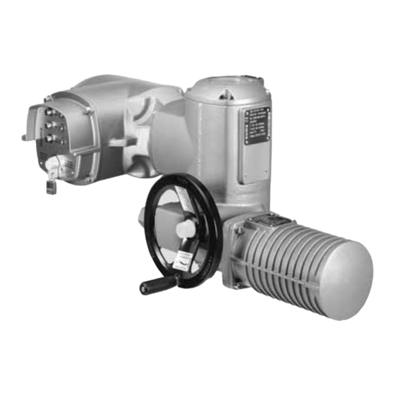
- Page 1 Part-turn actuators SG 05.1 SG 12.1/SGR 05.1 SGR 12.1 with actuator controls AUMA MATIC AM 01.1 Operation instructions Assembly, operation, commissioning...
-
Page 2: Table Of Contents
This document contains information for installation, commissioning, operation and maintenance staff. It is intended to support device installation and commissioning. Reference documents: Reference documents can be downloaded from the Internet (www.auma.com) or ordered directly from AUMA (refer to <Addresses>). Table of contents Page Safety instructions......................... - Page 3 SG 05.1 SG 12.1/SGR 05.1 SGR 12.1 AM 01.1 Table of contents Operation..........................6.1. Manual operation 6.1.1 Manual operation: engage 6.1.2 Manual operation: disengage 6.2. Motor operation 6.2.1 Local operation 6.2.2 Actuator operation from remote Indications..........................7.1. Indication lights 7.2. Mechanical position indicator/running indication Signals.............................
- Page 4 Features and functions of actuator controls 13.3. Service conditions 13.4. Further information Spare parts..........................14.1. Part-turn actuators SG 05.1 SG 12.1/SGR 05.1 SGR 12.1 14.2. Actuator controls AUMA MATIC AM 01.1/AM 02.1 Certificates..........................15.1. Declaration of Incorporation and EC Declaration of Conformity Index............................Addresses..........................
-
Page 5: Safety Instructions
Any device modification requires prior consent of the manufacturer. Range of application AUMA part-turn actuators are designed for the operation of industrial valves, e.g. butterfly valves and ball valves. Other applications require explicit (written) confirmation by the manufacturer. -
Page 6: Applications In Ex Zone 22 (Option)
SG 05.1 SG 12.1/SGR 05.1 SGR 12.1 Safety instructions AM 01.1 Escalators Continuous duty Buried service Permanent submersion (observe enclosure protection) Potentially explosive areas, with the exception of zone 22 Radiation exposed areas in nuclear power plants No liability can be assumed for inappropriate or unintended use. Observance of these operation instructions is considered as part of the device's designated use. -
Page 7: References And Symbols
SG 05.1 SG 12.1/SGR 05.1 SGR 12.1 AM 01.1 Safety instructions Indicates a potentially hazardous situation with a low level of risk. Failure to observe this warning may result in minor or moderate injury. May also be used with property damage. Potentially hazardous situation. -
Page 8: Identification
Wiring diagram Control Type and size These instructions apply to the following devices: Part-turn actuators for open-close duty: SG 05.1, 07.1, 10.1, 12.1 Part-turn actuators for modulating duty: SGR 05.1, 07.1, 10.1, 12.1 AM 01.1/02.1 = Actuator controls AUMA MATIC... -
Page 9: Short Description
A part-turn actuator is an actuator which transmits a torque to the valve for less than one full revolution. It need not be capable of withstanding thrust. AUMA part-turn actuators are driven by an electric motor. A handwheel is provided for manual operation. Switching off in end positions may be either by limit or torque seating. -
Page 10: Transport, Storage And Packaging
SG 05.1 SG 12.1/SGR 05.1 SGR 12.1 Transport, storage and packaging AM 01.1 Transport, storage and packaging Transport For transport to place of installation, use sturdy packaging. Hovering load! Risk of death or serious injury. Do NOT stand below hovering load. Attach ropes or hooks for the purpose of lifting by hoist only to housing and NOT to handwheel. -
Page 11: Assembly
AM 01.1 Assembly Assembly Mounting position AUMA actuators and actuator controls can be operated without restriction in any mounting position. Ball handle: fit to handwheel To avoid damage during transport, the ball handle is fitted at the rear of the handwheel. -
Page 12: Coupling
SG 05.1 SG 12.1/SGR 05.1 SGR 12.1 Assembly AM 01.1 4.3.1 Coupling Figure 6: Coupling fitting dimensions Coupling Valve shaft Grub screw Screw Table 1: Coupling fitting dimensions Type, size - mounting flange X max [mm] Y max [mm] Z max [mm] SG/SGR 05.1-F05 SG/SGR 05.1-F07 SG/SGR 07.1-F07... -
Page 13: Mounting Positions Of Local Controls
SG 05.1 SG 12.1/SGR 05.1 SGR 12.1 AM 01.1 Assembly Fasten actuator with screws [4]. Information: We recommend glueing the screws using sealing material to avoid contact corrosion. Fasten screws [4] crosswise with a torque according to table: Table 2: Tightening torques for screws Screws Tightening torque T... - Page 14 SG 05.1 SG 12.1/SGR 05.1 SGR 12.1 Assembly AM 01.1 Loosen 3 screws of the board, turn board to the new position and fasten the screws. Check whether O-ring is in good condition, correctly insert O-ring. Turn local controls into new position and re-place. Cable damage due to twisting or pinching! Risk of functional failures.
-
Page 15: Electrical Connection
The pertaining wiring diagram/terminal plan (in German and English language) is plan attached to the device in a weather-proof bag, together with these operation instructions. It can also be obtained from AUMA (state commission no., refer to name plate) or downloaded directly from the Internet (www.auma.com). Protection on site For short-circuit protection and for disconnecting the actuator from the mains, fuses and disconnect switches have to be provided by the customer. -
Page 16: Connection With Auma Plug/Socket Connector
PE connection : max. 6 mm² flexible/10 mm² solid Control contacts (1 to 50): max. 2.5 mm² 5.2.1 Terminal compartment: open Figure 10: Connection AUMA plug/socket connector, version S Cover Screws for cover O-ring Screws for socket carrier Socket carrier... -
Page 17: Cable Connection
SG 05.1 SG 12.1/SGR 05.1 SGR 12.1 AM 01.1 Electrical connection Hazardous voltage! Risk of electric shock. Disconnect device from the mains before opening. Loosen screws [2] and remove cover [1]. Loosen screws [4] and remove socket carrier [5] from cover [1]. Insert cable glands [8] suitable for connecting cables. - Page 18 SG 05.1 SG 12.1/SGR 05.1 SGR 12.1 Electrical connection AM 01.1 In case of a fault: Hazardous voltage while protective earth conductor is NOT connected! Risk of electric shock. Connect all protective earth conductors. Connect PE connection to external protective earth conductor of connecting cables.
-
Page 19: Terminal Compartment: Close
Permissible length of connecting cables: max. 100 m. Observe prior to If the actuator is equipped with a position transmitter (RWG): Connecting cables connection must be designed as shielded version. Versions with potentiometer in the actuator are not suitable. We recommend: AUMA cable set LSW1. -
Page 20: Parking Frame
SGR 12.1 Electrical connection AM 01.1 If the AUMA cable set is not used: Use suitable flexible and screened connecting cables. When using connecting cables, e.g. of the heater or switch, requiring direct wiring from the actuator to the XK customer plug (XA-XM-XK, refer to wiring diagram), these connecting cables must be subject to an insulation test in compliance with EN 50178. -
Page 21: Operation
SG 05.1 SG 12.1/SGR 05.1 SGR 12.1 AM 01.1 Operation Operation Manual operation For purposes of setting and commissioning, in case of motor failure or power failure, the actuator may be operated manually. The handwheel does not rotate during motor operation. Change-over from motor operation to manual operation is not required. -
Page 22: Actuator Operation From Remote
SG 05.1 SG 12.1/SGR 05.1 SGR 12.1 Operation AM 01.1 Figure 17: Local controls Push button for operation command in direction OPEN Push button Stop Push button for operation command in direction CLOSE Selector switch Hot surfaces, e.g. possibly caused by high ambient temperatures or strong direct sunlight! Danger of burns Check surface temperature and wear protective gloves, if required. - Page 23 SG 05.1 SG 12.1/SGR 05.1 SGR 12.1 AM 01.1 Operation Information For actuators equipped with positioner, it is possible to optionally select between open-close duty (REMOTE OPEN-CLOSE) and modulating duty (REMOTE SETPOINT). Selection is made via REMOTE MANUAL input, e.g. based on a 24 V DC signal (refer to wiring diagram).
-
Page 24: Indications
SG 05.1 SG 12.1/SGR 05.1 SGR 12.1 Indications AM 01.1 Indications Indication lights The colours of the 3 indication lights on the local controls and the assignment of the signals are specified in the order. Figure 20: Local controls with indication lights (default signalling) illuminated (green): End position OPEN reached illuminated (red): Collective fault signal illuminated (yellow): End position CLOSED reached... - Page 25 SG 05.1 SG 12.1/SGR 05.1 SGR 12.1 AM 01.1 Indications Figure 21: Mechanical position indicator Cover Indicator disc Mark Symbol for position OPEN Symbol for position CLOSED...
-
Page 26: Signals
SG 05.1 SG 12.1/SGR 05.1 SGR 12.1 Signals AM 01.1 Signals Feedback signals via output contacts (binary) The output contacts can be used to indicate operation modes of the actuator or the controls as binary signals. The signals are assigned according to the order. Example: Output contact open = end position CLOSED not reached Output contact closed = end position CLOSED reached Switches: 1 NC and 1 NO (standard) -
Page 27: Commissioning (Basic Settings)
SG 05.1 SG 12.1/SGR 05.1 SGR 12.1 AM 01.1 Commissioning (basic settings) Commissioning (basic settings) Set selector switch to position 0 (OFF). Information: The selector switch is not a mains switch. When positioned to 0 (OFF), the actuator cannot be operated. The controls' power supply is maintained. -
Page 28: End Stop Closed: Set
SG 05.1 SG 12.1/SGR 05.1 SGR 12.1 Commissioning (basic settings) AM 01.1 Exposed, rotating parts (discs/balls) at the valve! Pinching and damage by valve or actuator. End stops may be set by suitably qualified personnel only. Set end stops to ensure that they are NOT reached during normal operation. Information The setting sequence depends on the valve: Recommendations for butterfly valves: Set end position CLOSED first. -
Page 29: End Stop Open: Set
SG 05.1 SG 12.1/SGR 05.1 SGR 12.1 AM 01.1 Commissioning (basic settings) 9.2.2 End stop OPEN: set Figure 25: End stop Screws End stop nut Protective cap If the four screws [1] are fastened: Unfasten the screws [1] with approx. 3 turns. Move valve to end position OPEN with handwheel. -
Page 30: Swing Angle: Modify
SG 05.1 SG 12.1/SGR 05.1 SGR 12.1 Commissioning (basic settings) AM 01.1 9.3.1 Swing angle: modify Figure 27: End stop Grub screw End stop nut Protective cap Travelling nut Sealing ring Unfasten protective cap [3]. While holding end stop nut [2] in position with open end spanner, unfasten grub screw [1]. -
Page 31: Torque Switching: Set
SG 05.1 SG 12.1/SGR 05.1 SGR 12.1 AM 01.1 Commissioning (basic settings) Loosen screws [2] and remove cover [1] from the switch compartment. Figure 28: If indicator disc [3] is available: Remove indicator disc [3] using a spanner (as lever). Information: To avoid damage to paint finish, use spanner in combination with soft object, e.g. -
Page 32: Limit Switching: Set
SG 05.1 SG 12.1/SGR 05.1 SGR 12.1 Commissioning (basic settings) AM 01.1 Figure 30: Torque switching heads Torque switching head black in direction CLOSE Torque switching head white in direction OPEN Lock screws Torque dials Loosen both lock screws [3] at the indicator disc. Turn torque dial [4] to set the required torque (1 da Nm = 10 Nm). -
Page 33: End Position Open (White Section): Set
SG 05.1 SG 12.1/SGR 05.1 SGR 12.1 AM 01.1 Commissioning (basic settings) To prevent that the end stop is reached (due to overrun) before the limit switch has tripped, turn handwheel 4 turns (overrun) in the opposite direction. Press down and turn setting spindle [1] with screw driver in direction of the arrow and observe the pointer [2]: While a ratchet click is felt and heard, the pointer [2] moves 90°... -
Page 34: Running Direction Close (Black Section): Set
SG 05.1 SG 12.1/SGR 05.1 SGR 12.1 Commissioning (basic settings) AM 01.1 9.7.1 Running direction CLOSE (black section): set Move valve in direction CLOSE to desired intermediate position. If you override the tripping point inadvertently: Turn valve in opposite direction and approach intermediate position again in direction CLOSE. -
Page 35: Limit Switching: Check
"collective fault signal" on the local con- trols. Turn selector switch to position Reset. The fault signal is reset if the device is working properly. If no fault signal is initiated: Request AUMA service to check both wiring and selector switch. -
Page 36: Potentiometer Setting
SG 05.1 SG 12.1/SGR 05.1 SGR 12.1 Commissioning (basic settings) AM 01.1 Potentiometer setting — Option — The potentiometer as travel sensor records the valve position. Information This setting is only required if the potentiometer is directly wired to the customer connection XK (refer to wiring diagram). -
Page 37: Mechanical Position Indicator: Set
SG 05.1 SG 12.1/SGR 05.1 SGR 12.1 AM 01.1 Commissioning (basic settings) Figure 39: View of control unit Potentiometer (travel sensor) Potentiometer min. (0/4 mA) Potentiometer max. (20 mA) Measuring point (+) 0/4 20 mA Measuring point ( ) 0/4 20 mA Connect voltage to electronic position transmitter. -
Page 38: Switch Compartment: Close
SG 05.1 SG 12.1/SGR 05.1 SGR 12.1 Commissioning (basic settings) AM 01.1 Hold lower indicator disc in position and turn upper disc with symbol (OPEN) until it is in alignment with the mark on the cover. Move valve to end position CLOSED again. Check settings: If the symbol (CLOSED) is no longer in alignment with mark... - Page 39 SG 05.1 SG 12.1/SGR 05.1 SGR 12.1 AM 01.1 Commissioning (basic settings) Figure 43: Part-turn actuator with 1-ph AC motor Motor cover Potentiometer Hazardous voltage! Risk of electric shock. Disconnect device from the mains before opening. Danger of corrosion due to damage to paint finish! Touch up damage to paint finish after work on the device.
-
Page 40: Commissioning
SG 05.1 SG 12.1/SGR 05.1 SGR 12.1 Commissioning controls settings AM 01.1 Commissioning controls settings The controls are set in the factory according to the order. The settings only have to be changed if the device is used for applications other than those specified in the order. -
Page 41: Push-To-Run Operation Or Self-Retaining: Set
SG 05.1 SG 12.1/SGR 05.1 SGR 12.1 AM 01.1 Commissioning controls settings The limit seating is used to signal that the limit switching will trip shortly before reaching the set tripping torque. If this is not the case, either the indication light on the local controls or the alarm contact K9 (collective fault signal) will signal a fault. -
Page 42: Running Indication (Blinker Transmitter): Activate/Deactivate
SG 05.1 SG 12.1/SGR 05.1 SGR 12.1 Commissioning controls settings AM 01.1 Information If the controls are equipped with a positioner, switches 1 and 2 (operation commands from remote) must be in position OFF (push-to-run operation). 10.4 Running indication (blinker transmitter): activate/deactivate —... -
Page 43: Input Ranges (Signal Type) For Setpoint And Actual Value
SG 05.1 SG 12.1/SGR 05.1 SGR 12.1 AM 01.1 Commissioning controls settings Prior to positioner setting, set limit and torque switching as well as potentiometer or electronic position transmitter. 10.6.1 Input ranges (signal type) for setpoint and actual value The input range (signal type) for setpoint E1 and actuator value E2 is set in the factory and marked with a label on the cover plate of the positioner. - Page 44 SG 05.1 SG 12.1/SGR 05.1 SGR 12.1 Commissioning controls settings AM 01.1 The following reactions are possible: Actuator stops immediately and remains in this position. Fail as is: Fail close: Actuator moves the valve to end position CLOSED. Fail open: Actuator moves the valve to end position OPEN.
-
Page 45: Adjustment In End Positions
SG 05.1 SG 12.1/SGR 05.1 SGR 12.1 AM 01.1 Commissioning controls settings 10.6.3 Adjustment in end positions The setting described below applies to the standard positioner version, i.e. maximum setpoint E1 (20 mA) triggers a travel to end position OPEN, minimum setpoint (0/4 mA) triggers a travel to end position CLOSED. -
Page 46: Sensitivity Setting
SG 05.1 SG 12.1/SGR 05.1 SGR 12.1 Commissioning controls settings AM 01.1 Adjust positioner using potentiometer 0 [P3]. 9.1 If both LEDs are OFF or the green LED [V28] is illuminated: Turn potentio- meter 0 [P3] slightly clockwise until the yellow LED [V27] is illuminated. 9.2 If the yellow LED [V27] is illuminated: Turn potentiometer 0 [P3] counter- clockwise until the yellow LED [V27] goes out. -
Page 47: Emergency Command (Emergency - Open/Emergency - Close)
SG 05.1 SG 12.1/SGR 05.1 SGR 12.1 AM 01.1 Commissioning controls settings Default value: 2.5 % Setting range: 0.5 % to 2.5 % (of the maximum setpoint E1) The dead time prevents the operation to a new setpoint within a pre-determined time Dead time (0.5 to 10 seconds). -
Page 48: Controls: Close
SG 05.1 SG 12.1/SGR 05.1 SGR 12.1 Commissioning controls settings AM 01.1 Disable EMERGENCY Figure 54:Interface board for available option EMERGENCY - OPEN/EMERGENCY command - CLOSE [B1] Link available: EMERGENCY - CLOSE [B2] Link available: EMERGENCY - OPEN Remove face plate. Disconnect links [B1] or [B2]. -
Page 49: Corrective Action
SG 05.1 SG 12.1/SGR 05.1 SGR 12.1 AM 01.1 Corrective action Corrective action 11.1 Faults during commissioning Table 11: Faults during commissioning Fault description Possible causes Remedy Fault in end position The overrun was not considered when setting Determine overrun: Overrun = travel covered Actuator runs to end stop alt- the limit switching. -
Page 50: Motor Protection (Thermal Monitoring)
Local controls Signal and control board Power supply unit Primary fuses on power supply unit F1/F2 G fuses F1/F2 AUMA Art. no.: Size 6.3 x 32 mm Reversing contactors 1 A T; 500 V K002.277 Power supply≤ 500 V Reversing contactors 2 A FF;... - Page 51 SG 05.1 SG 12.1/SGR 05.1 SGR 12.1 AM 01.1 Corrective action winding. The thermoswitch is tripped as soon as the max. permissible winding temperature has been reached. The actuator is stopped and the red indication light on the local controls is illuminated. The motor has to cool down before the operation can be resumed.
-
Page 52: Servicing And Maintenance
Only perform servicing and maintenance tasks when the device is switched off. AUMA AUMA offer extensive service such as servicing and maintenance as well as customer Service & Support product training. For the relevant contact addresses, please refer to <Addresses>... -
Page 53: Technical Data
The following technical data includes standard and optional features. For detailed information on the customer-specific version, refer to the order-relevant data sheet. This data sheet can be downloaded from the Internet at http://www.auma.com in German and English (indication of commission number required). -
Page 54: Features And Functions Of Actuator Controls
SG 05.1 SG 12.1/SGR 05.1 SGR 12.1 Technical data AM 01.1 Technical data for limit and torque switches Mechanical lifetime 2 x 10 starts Silver plated contacts: U min. 30 V AC/DC U max. 250 V AC/DC I min. 20 mA I max. - Page 55 SG 05.1 SG 12.1/SGR 05.1 SGR 12.1 AM 01.1 Technical data Control Standard: Control inputs 24 V DC, OPEN - STOP - CLOSE (via opto-isolator, one common), current consumption: approx. 10 mA per input, observe minimum pulse duration for modulating ac- tuators Option: Control inputs 115 V AC, OPEN - STOP - CLOSE - EMERGENCY (via opto-isolator, one...
-
Page 56: Service Conditions
IP 68 IP 68-DS IP 67-DS According to AUMA definition, enclosure protection IP 68 meets the following requirements: Water depth: Maximum 6 m head of water Duration of continuous immersion in water: maximum of 72 hours Up to 10 operations during flooding Modulating duty is not possible during continuous immersion. -
Page 57: Further Information
SG 05.1 SG 12.1/SGR 05.1 SGR 12.1 AM 01.1 Technical data Ambient temperature Refer to name plate Standard: 25 °C to +70 °C Options: 40 °C to +70 °C 50 °C to +70 °C Low temperature versions incl. heating system for connection to external power supply 230 V AC or 115 V AC. -
Page 58: Spare Parts
SG 05.1 SG 12.1/SGR 05.1 SGR 12.1 Spare parts AM 01.1 Spare parts 14.1 Part-turn actuators SG 05.1 SG 12.1/SGR 05.1 SGR 12.1... - Page 59 Information: Please state type and commission no. of the device (see name plate) when ordering spare parts. Only original AUMA spare parts should be used. Failure to use original spare parts voids the warranty and exempts AUMA from any liability. Delivered spare parts may slightly vary from the representation.
-
Page 60: Actuator Controls Auma Matic Am 01.1/Am
SG 05.1 SG 12.1/SGR 05.1 SGR 12.1 Spare parts AM 01.1 14.2 Actuator controls AUMA MATIC AM 01.1/AM 02.1... - Page 61 Information: Please state type and commission no. of the device (see name plate) when ordering spare parts. Only original AUMA spare parts should be used. Failure to use original spare parts voids the warranty and exempts AUMA from any liability. Delivered spare parts may slightly vary from the representation.
-
Page 62: Certificates
SG 05.1 SG 12.1/SGR 05.1 SGR 12.1 Certificates AM 01.1 Certificates 15.1 Declaration of Incorporation and EC Declaration of Conformity... -
Page 63: Index
SG 05.1 SG 12.1/SGR 05.1 SGR 12.1 AM 01.1 Index Index Identification Indication lights Indications Accessories (electrical Indicator disc 24 , 37 connection) Input ranges Actual value Inspection record Actuator operation from remo- Intermediate frame Intermediate positions Ambient temperature Analogue signals Applications Limit seating Assembly... - Page 64 SG 05.1 SG 12.1/SGR 05.1 SGR 12.1 Index AM 01.1 Range of application Recycling Remote actuator operation Running indication 24 , 24 Running indication: activa- te/deactivate Safety instructions Safety instructions/warnings Self-retaining: set Service Service conditions Servicing Setpoint Short-circuit protection Signal type Signals Signals (analogue) Spare parts...
-
Page 65: Addresses
Auma Endüstri Kontrol Sistemleri Limited UK Clevedon, North Somerset BS21 6TH irketi Tel +44 1275 871141 TR 06810 Ankara AUMA Riester GmbH & Co. KG Fax +44 1275 875492 Tel+90 312 217 32 88 mail@auma.co.uk Fax+90 312 217 33 88 Plant Müllheim... - Page 66 AUMA worldwide Ferrostaal de Colombia Ltda. AUMA Actuators Middle East W.L.L. CO Bogotá D.C. AE 15268 Salmabad 704 Tel +57 1 401 1300 Tel +973 17877377 Fax+57 1 416 5489 Fax +973 17877355 dorian.hernandez@ferrostaal.com Naveen.Shetty@auma.com www.ferrostaal.com PERFECT CONTROLS Ltd. PROCONTIC Procesos y Control HK Tsuen Wan, Kowloon Automático...
- Page 67 AUMA worldwide...
- Page 68 AUMA Riester GmbH & Co. KG P.O.Box 1362 D 79373 Muellheim Tel +49 7631 809 - 0 Fax +49 7631 809 - 1250 riester@auma.com www.auma.com Y000.238/003/en/1.13 For detailed information on AUMA products refer to the Internet: www.auma.com...
Need help?
Do you have a question about the SG 05.1-F05 and is the answer not in the manual?
Questions and answers