
Related Manuals for AUMA SG 05.1-FA07


Summary of Contents for AUMA SG 05.1-FA07
- Page 1 Electric part-turn actuators SG 05.1 – SG 12.1 SGR 05.1 – SGR 12.1 AUMA NORM for flange type FA Operation instructions...
-
Page 2: Table Of Contents
These instructions are valid for part-turn actuators of the type ranges Scope of these instructions: SG 05.1 – SG 12.1 and SGR 05.1 – SGR 12.1 in version AUMA NORM. These operation instructions are only valid for “clockwise closing”, i.e. - Page 3 Setting the mechanical position indicator Closing the switch compartment Setting the operating time Enclosure protection IP 68 (option) Maintenance Lubrication Disposal and recycling Service Spare parts list part-turn actuator SG(R) 05.1 – SG(R) 12.1 with plug/socket connector Index Addresses of AUMA offices and representatives...
-
Page 4: Safety Instructions
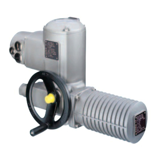
Short description AUMA part-turn actuators type SG 05.1 – SG 12.1 and SGR 05.1 – SGR 12.1 have a modular design. The part-turn actuators are driven by an electric motor. A handwheel is provided for manual operation. The limitation of travel is realised via limit switches in both end positions. -
Page 5: Technical Data
Operation instructions AUMA NORM Technical data Part-turn actuators AUMA NORM require external controls. AUMA offers actuator controls AUMA MATIC AM or AUMATIC AC. These can also easily be mounted to the actuator at a later date. Features and functions Type of duty... - Page 6 Part-turn actuators SG 05.1 – SG 12.1 / SGR 05.1 – SGR 12.1 AUMA NORM Operation instructions Service conditions Enclosure protection according Standard: IP 67 to EN 60 529 Options: IP 68 IP 67-DS (Double Sealed) IP 68-DS (Double Sealed)
-
Page 7: Transport, Storage And Packaging
Part-turn actuators SG 05.1 – SG 12.1 / SGR 05.1 – SGR 12.1 Operation instructions AUMA NORM Transport, storage and packaging Transport For transport to place of installation, use sturdy packaging. Do not attach ropes or hooks to the handwheel for the purpose of lifting by hoist. -
Page 8: Manual Operation
Part-turn actuators SG 05.1 – SG 12.1 / SGR 05.1 – SGR 12.1 AUMA NORM Operation instructions Manual operation The actuator may be operated manually for purposes of setting and commissioning, and in case of motor failure or power failure. -
Page 9: Mounting To Valve
Part-turn actuators SG 05.1 – SG 12.1 / SGR 05.1 – SGR 12.1 Operation instructions AUMA NORM Mounting to valve Prior to mounting, the part-turn actuator must be checked for any damage. Damaged parts must be replaced by origi- nal spare parts. -
Page 10: Electrical Connection
Brass (Ms) Brass (Ms) Brass, tin plated or gold plated (option) 1) Suitable for copper wires. For aluminium wires, please contact AUMA Delay time The delay time is the time from the tripping of the limit or torque switches to the motor power being removed. -
Page 11: Controls Made By Auma
Controls made by AUMA In case the required reversing contactors are not to be installed in the control cabinet, the controls AUMA MATIC or AUMATIC can easily be mounted to the actuator at a later date. For enquiries and more information, please state our commission no. -
Page 12: Setting The End Stops For Part-Turn Actuators On Butterfly Valves
Part-turn actuators SG 05.1 – SG 12.1 / SGR 05.1 – SGR 12.1 AUMA NORM Operation instructions Setting the end stops for part-turn actuators on butterfly valves For actuators on ball valves refer to page 13, section 9. The settings can only be performed if the valve has not yet been mounted in a pipeline. -
Page 13: Setting The End Stops For Part-Turn Actuators On Ball Valves
Part-turn actuators SG 05.1 – SG 12.1 / SGR 05.1 – SGR 12.1 Operation instructions AUMA NORM Setting the end stops for part-turn actuators on ball valves For actuators on butterfly valves refer to page 12, section 8. The settings can only be performed if the valve has not yet been mounted in a pipeline. -
Page 14: Changing The Swing Angle
Part-turn actuators SG 05.1 – SG 12.1 / SGR 05.1 – SGR 12.1 AUMA NORM Operation instructions 10. Changing the swing angle The swing angle only has to be changed if the swing range for setting the end stops (sections 8. and 9.) is not sufficient. -
Page 15: Opening The Switch Compartment
Part-turn actuators SG 05.1 – SG 12.1 / SGR 05.1 – SGR 12.1 Operation instructions AUMA NORM 11. Opening the switch To be able to carry out the following settings (sections 13.12. to 18.), the compartment switch compartment must be opened and the indicator disc must be removed. -
Page 16: Setting The Limit Switching
Part-turn actuators SG 05.1 – SG 12.1 / SGR 05.1 – SGR 12.1 AUMA NORM Operation instructions 12. Setting the limit switching 12.1 Setting end position CLOSED (black section) Turn handwheel clockwise until valve is closed. To prevent that the end stop is reached (due to overrun) before the limit switch has tripped, turn handwheel 4 turns (overrun) in counterclockwise direction. -
Page 17: Setting The Duo Limit Switching (Option)
Part-turn actuators SG 05.1 – SG 12.1 / SGR 05.1 – SGR 12.1 Operation instructions AUMA NORM 13. Setting the DUO limit switching (option) Any application can be switched on or off via the two intermediate position switches. For setting, the switching point (intermediate position) must be approached from the same direction as afterwards in electrical operation. - Page 18 Part-turn actuators SG 05.1 – SG 12.1 / SGR 05.1 – SGR 12.1 AUMA NORM Operation instructions 14. Setting the torque switching 14.1 Setting The set torque must suit the valve! This setting must only be changed with the consent of the...
- Page 19 Part-turn actuators SG 05.1 – SG 12.1 / SGR 05.1 – SGR 12.1 Operation instructions AUMA NORM 15. Test run 15.1 Checking the Place indicator disc on shaft. direction of rotation The direction of rotation of the indicator disc (figure M) indicates the direc- tion of rotation of the output drive.
- Page 20 Part-turn actuators SG 05.1 – SG 12.1 / SGR 05.1 – SGR 12.1 AUMA NORM Operation instructions 16. Setting the potentiometer (option) — For remote indication — Move valve to end position CLOSED. Pull off indicator disc. Turn potentiometer (E2) counterclockwise until stop is felt.
- Page 21 Part-turn actuators SG 05.1 – SG 12.1 / SGR 05.1 – SGR 12.1 Operation instructions AUMA NORM 17. Setting the electronic position transmitter RWG (option) — For remote indication or external control — After mounting the part-turn actuator to the valve, check setting by measuring the output current (see sections 17.1 or 17.2) and re-adjust, if...
- Page 22 Part-turn actuators SG 05.1 – SG 12.1 / SGR 05.1 – SGR 12.1 AUMA NORM Operation instructions 17.1 Setting 2-wire system 4 – 20 mA and 3- /4-wire system 0 – 20 mA Connect voltage to electronic position transmitter. Move valve to end position CLOSED.
- Page 23 Part-turn actuators SG 05.1 – SG 12.1 / SGR 05.1 – SGR 12.1 Operation instructions AUMA NORM 17.2 Setting 3-/4- wire system 4 – 20 mA Connect voltage to electronic position transmitter. Move valve to end position CLOSED. Pull off indicator disc.
- Page 24 Part-turn actuators SG 05.1 – SG 12.1 / SGR 05.1 – SGR 12.1 AUMA NORM Operation instructions 18. Setting the mechanical position indicator Place indicator disc on shaft. Move valve to end position CLOSED. Turn lower indicator disc (figure Q-1) until symbol CLOSED is in align- ment with the mark on the cover (figure Q-2).
- Page 25 Part-turn actuators SG 05.1 – SG 12.1 / SGR 05.1 – SGR 12.1 Operation instructions AUMA NORM 20. Setting the operating time For part-turn actuators with 1-phase AC motors, the operating time can be adjusted. Work on the electrical system or equipment must only be...
- Page 26 As standard, actuators and controls are delivered without cable glands. For delivery, the threads are sealed with plugs in the factory. When ordered, cable glands can also be supplied by AUMA at an addi- tional charge. For this, it is necessary to state the outside diameter of the cables.
- Page 27 If required, tighten applying the torques given in table 1, page 9. 23. Lubrication AUMA part-turn actuators are filled with grease for lifetime. A change of grease or re-lubrication is not necessary.
- Page 28 AUMA NORM Operation instructions 24. Disposal and recycling AUMA actuators have an extremely long lifetime. However, they have to be replaced at one point in time. The actuators have a modular design and may therefore easily be disas- sembled, separated, and sorted according to materials, i.e.:...
- Page 29 Part-turn actuators SG 05.1 – SG 12.1 / SGR 05.1 – SGR 12.1 Operation instructions AUMA NORM 26. Spare parts list part-turn actuator SG(R) 05.1 – SG(R) 12.1 with plug/socket connector...
- Page 30 Part-turn actuators SG 05.1 – SG 12.1 / SGR 05.1 – SGR 12.1 AUMA NORM Operation instructions Note: Please state type and commission no. of the actuator (see name plate) when ordering spare parts. Delivered spare parts may slightly vary from the representation in these instructions.
- Page 31 Part-turn actuators SG 05.1 – SG 12.1 / SGR 05.1 – SGR 12.1 Operation instructions AUMA NORM Index Ambient temperature Limit switches Safety instructions Limit switching 16,17 Service Lubrication Spare parts list Corrosion protection 7,27 Part-turn actuator Storage Maintenance Swing angle...
- Page 32 North American Sales and Service: International Headquarters: AUMA Riester GmbH & Co. KG US Headquarters and Factory: Müllheim/ Germany AUMA Actuators, Inc. www.auma.com 100 Southpointe Blvd. International Sales and Service: Canonsburg PA 15317 Tel: 724-743-AUMA (2862) South America: Fax: 724-743-4711 Argentina email: mailbox@auma-usa.com...
Need help?
Do you have a question about the SG 05.1-FA07 and is the answer not in the manual?
Questions and answers