Table of Contents
Advertisement
Advertisement
Table of Contents

Related Manuals for AUMA SG 05.1-F05


Summary of Contents for AUMA SG 05.1-F05
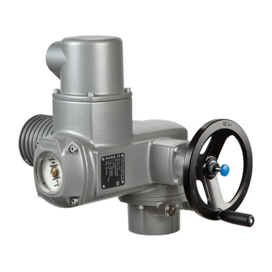
- Page 1 Part-turn actuators SG 05.1 – SG 12.1/SGR 05.1 – SGR 12.1 Control unit: electromechanic with actuator controls AUMATIC AC 01.1 Intrusive Control Parallel Profibus DP Profibus DP with FOC → Modbus Modbus with FOC DeviceNet Foundation Fieldbus Operation instructions Assembly, operation, commissioning...
-
Page 2: Table Of Contents
Manual (Operation and setting) AUMATIC AC 01.1/ACExC 01.1 Modbus ● Manual (Device integration Fieldbus) AUMATIC AC 01.1/ACExC 01.1 Modbus ● Reference documents can be downloaded from the Internet (www.auma.com) or ordered directly from AUMA (refer to <Addresses>). Table of contents Page Safety instructions......................... - Page 3 SG 05.1 – SG 12.1/SGR 05.1 – SGR 12.1 Control unit: electromechanic AC 01.1 Intrusive Modbus RTU Table of contents 5.3.2 Parking frame 5.3.3 Protection cover 5.3.4 Double sealed intermediate frame 5.3.5 Earth connection, external Operation..........................6.1. Manual operation 6.1.1 Manual operation: engage 6.1.2 Manual operation: disengage...
- Page 4 12.6. Further information Spare parts..........................13.1. Part-turn actuators SG 05.1 – SG 12.1/SGR 05.1 – SGR 12.1 13.2. Actuator controls AUMATIC AC 01.1 with AUMA plug/socket connector(SD bus) Certificates..........................14.1. Declaration of Incorporation and EC Declaration of Conformity Index............................Addresses..........................
-
Page 5: Safety Instructions
Any device modification requires prior consent of the manufacturer. Range of application AUMA part-turn actuators are designed for the operation of industrial valves, e.g. butterfly valves and ball valves. Other applications require explicit (written) confirmation by the manufacturer. -
Page 6: Applications In Ex Zone 22 (Option)
SG 05.1 – SG 12.1/SGR 05.1 – SGR 12.1 Control unit: electromechanic Safety instructions AC 01.1 Intrusive Modbus RTU Service lifts according to EN 81-1/A1 ● Roller conveyors according to EN 14673 (draft) ● Continuous operation ● Buried service ● Permanent submersion (observe enclosure protection) ●... -
Page 7: References And Symbols
SG 05.1 – SG 12.1/SGR 05.1 – SGR 12.1 Control unit: electromechanic AC 01.1 Intrusive Modbus RTU Safety instructions Indicates a potentially hazardous situation with a low level of risk. Failure to observe this warning may result in minor or moderate injury. May also be used with property damage. -
Page 8: Identification
SG 05.1 – SG 12.1/SGR 05.1 – SGR 12.1 Control unit: electromechanic Identification AC 01.1 Intrusive Modbus RTU Identification Name plate Each device component (actuator, controls, motor) is equipped with a name plate. Figure 1: Arrangement of name plates Actuator name plate Controls name plate Motor name plate Additional plate, e.g. -
Page 9: Short Description
A part-turn actuator is an actuator which transmits a torque to the valve for less than one full revolution. It need not be capable of withstanding thrust. AUMA part-turn actuators are driven by an electric motor. A handwheel is provided for manual operation. Switching off in end positions may be either by limit or torque seating. - Page 10 SG 05.1 – SG 12.1/SGR 05.1 – SGR 12.1 Control unit: electromechanic Identification AC 01.1 Intrusive Modbus RTU Non-Intrusive version (control unit: electronic): ● Limit and torque setting is performed via the controls, actuator and controls housings do not have to be opened. For this purpose, the actuator is equipped with an MWG (magnetic limit and torque transmitter), also supplying analogue torque feedback signals/torque indication and analogue position feedback si- gnals/position indication.
-
Page 11: Transport, Storage And Packaging
SG 05.1 – SG 12.1/SGR 05.1 – SGR 12.1 Control unit: electromechanic AC 01.1 Intrusive Modbus RTU Transport, storage and packaging Transport, storage and packaging Transport For transport to place of installation, use sturdy packaging. Hovering load! Death or serious injury possible. →... -
Page 12: Assembly
AC 01.1 Intrusive Modbus RTU Assembly Mounting position AUMA actuators and actuator controls can be operated without restriction in any mounting position. Ball handle: fit to handwheel To avoid damage during transport, the ball handle is fitted at the rear of the handwheel. -
Page 13: Coupling
SG 05.1 – SG 12.1/SGR 05.1 – SGR 12.1 Control unit: electromechanic AC 01.1 Intrusive Modbus RTU Assembly 4.3.1 Coupling Figure 7: Mounting dimensions coupling Coupling Valve shaft Grub screw Screw Table 1: Mounting dimensions coupling Type, size - mounting flange X max [mm] Y max [mm] Z max [mm]... -
Page 14: Mounting Positions Of Local Controls
SG 05.1 – SG 12.1/SGR 05.1 – SGR 12.1 Control unit: electromechanic Assembly AC 01.1 Intrusive Modbus RTU Fasten actuator with screws [4]. Information: We recommend glueing the screws using sealing material to avoid contact corrosion. → Fasten screws [4] crosswise with a torque according to table: Table 2: Fastening torques for screws Screws... - Page 15 SG 05.1 – SG 12.1/SGR 05.1 – SGR 12.1 Control unit: electromechanic AC 01.1 Intrusive Modbus RTU Assembly Turn local controls into new position and re-place. Cable damage due to twisting or pinching! Functional failures possible. → Turn local controls by a maximum of 180°. →...
-
Page 16: Electrical Connection
The pertaining wiring diagram/terminal plan is attached to the device in a plan weather-proof bag, together with these operation instructions. It can also be obtained from AUMA (state commission no., refer to name plate) or downloaded directly from the Internet (www.auma.com). Protection on site For short-circuit protection and for disconnecting the actuator from the mains, fuses and disconnect switches have to be provided by the customer. - Page 17 SG 05.1 – SG 12.1/SGR 05.1 – SGR 12.1 Control unit: electromechanic AC 01.1 Intrusive Modbus RTU Electrical connection Signal and bus cables are susceptible to interference. Cable installation in ac- cordance with EMC Motor cables are interference sources. Lay cables being susceptible to interference or sources of interference at the ●...
-
Page 18: Connection With Auma Plug/Socket Connector
Terminal compartment: open Information The bus connection can be separately accessed from the mains connection (refer to <Bus terminal compartment: open>). Figure 11: Mains connection AUMA plug/socket connector SD bus Connection housing Screws for connection housing O-ring Screws for socket carrier... -
Page 19: Cable Connection
SG 05.1 – SG 12.1/SGR 05.1 – SGR 12.1 Control unit: electromechanic AC 01.1 Intrusive Modbus RTU Electrical connection Insert cable glands [8] suitable for connecting cables. ➥ The enclosure protection IP... stated on the name plate is only ensured if suitable cable glands are used. -
Page 20: Terminal Compartment: Close
Fasten cable glands [8] applying the specified torque to ensure the required enclosure protection. 5.2.4 Bus terminal compartment: open The AUMA plug/socket connector (SD bus) is equipped with a connection board for connecting the bus cables. When removing the cover [1] the connection board is easily accessible. -
Page 21: Bus Cables: Connect
For loop redundancy, automatic termination is performed as soon as the AUMATIC is connected to the power supply. When interrupting the power supply, e.g. after re- moving the AUMA plug/socket connector, both RS-485 loop segments are automa- tically connected to each other. - Page 22 SG 05.1 – SG 12.1/SGR 05.1 – SGR 12.1 Control unit: electromechanic Electrical connection AC 01.1 Intrusive Modbus RTU Figure 17: Connection board (standard version) [S1] Bus termination channel 1 [X1] Channel 1, from the previous device [X2] Channel 1, to the next device [X3] Shielding clamp...
- Page 23 Switches S1 and S2 are supplied in OFF position. Connecting bus cables: Connect cables. Table 6: Assignment of fieldbus cables Fieldbus cables AUMA labelling at the SUB-D 9 plug pin (for other Colour connection fieldbus devices) green If the actuator is the final device in the bus segment: 2.1 Switching on the termination resistor for channel 1 using switch S1 (ON...
-
Page 24: Bus Terminal Compartment: Close
SG 05.1 – SG 12.1/SGR 05.1 – SGR 12.1 Control unit: electromechanic Electrical connection AC 01.1 Intrusive Modbus RTU 5.2.6 Bus terminal compartment: close Figure 20: AUMA plug/socket connector SD bus Cover Screws for cover O-ring Cable entries for bus cables Blanking plug Clean sealing faces of cover [1] and housing. -
Page 25: Parking Frame
Versions with potentiometer in the actuator are not suitable. ● We recommend: AUMA cable set LSW1. ● If the AUMA cable set is not used: Use suitable flexible and screened connecting ● cables. When using connecting cables, e.g. of the heater or switch, requiring direct wiring ●... -
Page 26: Protection Cover
SG 05.1 – SG 12.1/SGR 05.1 – SGR 12.1 Control unit: electromechanic Electrical connection AC 01.1 Intrusive Modbus RTU 5.3.3 Protection cover Protection cover for plug compartment when plug is removed. The open terminal compartment can be closed using a protective cover (not illustrated). -
Page 27: Operation
SG 05.1 – SG 12.1/SGR 05.1 – SGR 12.1 Control unit: electromechanic AC 01.1 Intrusive Modbus RTU Operation Operation Manual operation In case of motor failure or power failure, the actuator may be operated manually for purposes of setting and commissioning. The handwheel does not rotate during motor operation. -
Page 28: Operation From Remote
SG 05.1 – SG 12.1/SGR 05.1 – SGR 12.1 Control unit: electromechanic Operation AC 01.1 Intrusive Modbus RTU Figure 25: Local controls Push button OPEN Push button STOP Push button CLOSE Push button Reset Selector switch Indication lights/LEDs Hot surfaces, e.g. possibly caused by high ambient temperatures or strong direct sunlight! Danger of burns →... -
Page 29: Menu Navigation Via Push Buttons (For Settings And Indications)
SG 05.1 – SG 12.1/SGR 05.1 – SGR 12.1 Control unit: electromechanic AC 01.1 Intrusive Modbus RTU Operation Information For actuators equipped with positioner, it is possible to select between open-close duty (REMOTE MODE) and modulating duty (SETPOINT MODE). For further infor- mation, please refer to the Manual (Operation and setting). -
Page 30: Password Entry
SG 05.1 – SG 12.1/SGR 05.1 – SGR 12.1 Control unit: electromechanic Operation AC 01.1 Intrusive Modbus RTU Group = Status indications ● Group = Menu (settings) ● Group = Diagnostic indications ● The active group is displayed in the top right corner of the display. Change from group to group Press push button... -
Page 31: Language Change In The Display
SG 05.1 – SG 12.1/SGR 05.1 – SGR 12.1 Control unit: electromechanic AC 01.1 Intrusive Modbus RTU Operation Language change in the display Via the menu to parameter: MAIN MENU (M0) LANGUAGE/CONTRAS (M00) VIEW (M00) EDIT (M01) LANGUAGE (M010) ENGLISH Default value: ENGLISH, GERMAN, MAGYAR, POLSKI, TUERKCE, Setting range:... - Page 32 SG 05.1 – SG 12.1/SGR 05.1 – SGR 12.1 Control unit: electromechanic Operation AC 01.1 Intrusive Modbus RTU Enter password: → Press 4 x = 0000 (default factory password). ➥ Display indicates: EDIT M010 LANGUAGE LCD CONTRAST Press ➥ Display shows the set value: EDIT M010 LANGUAGE...
-
Page 33: Indications
SG 05.1 – SG 12.1/SGR 05.1 – SGR 12.1 Control unit: electromechanic AC 01.1 Intrusive Modbus RTU Indications Indications Status indications in the display The status indications in the display locally indicate the current operation states as well as faults and warnings. This section describes the indications for the operation states. -
Page 34: Torque Indication: Edit
SG 05.1 – SG 12.1/SGR 05.1 – SGR 12.1 Control unit: electromechanic Indications AC 01.1 Intrusive Modbus RTU End position OPEN reached. CLOSED POSITION End position CLOSED reached. SETPOINT POSITION Setpoint (modulating actuators only). 7.1.2 Torque indication: edit The torque value can be displayed in percent, Newtonmeter (Nm) or in Lbs/ft. Via the menu to parameter: MAIN MENU (M0) SETTINGS (M1) -
Page 35: Mechanical Position Indicator/Running Indication
SG 05.1 – SG 12.1/SGR 05.1 – SGR 12.1 Control unit: electromechanic AC 01.1 Intrusive Modbus RTU Indications BLINKER (M1311) Information The behaviour (blinking/illuminated) can be changed via the parameter. Mechanical position indicator/running indication Mechanical position indicator: Continuously indicates the valve position ●... -
Page 36: Signals
SG 05.1 – SG 12.1/SGR 05.1 – SGR 12.1 Control unit: electromechanic Signals AC 01.1 Intrusive Modbus RTU Signals Signals via fieldbus The feedback signals via Modbus RTU can be read using the appropriate Modbus function codes. For further information, please refer to the Manual (Device integration fieldbus). Feedback signals via output contacts (binary) —... -
Page 37: Commissioning (Basic Settings)
SG 05.1 – SG 12.1/SGR 05.1 – SGR 12.1 Control unit: electromechanic AC 01.1 Intrusive Modbus RTU Commissioning (basic settings) Commissioning (basic settings) Set selector switch to position 0 (OFF). Information: The selector switch is not a mains switch. When positioned to 0 (OFF), the actuator cannot be operated. -
Page 38: End Stop Closed: Set
SG 05.1 – SG 12.1/SGR 05.1 – SGR 12.1 Control unit: electromechanic Commissioning (basic settings) AC 01.1 Intrusive Modbus RTU Exposed, rotating parts (discs/balls) at the valve! Pinching and damage by valve or actuator. → End stops may be set by suitably qualified personnel only. →... -
Page 39: End Stop Open: Set
SG 05.1 – SG 12.1/SGR 05.1 – SGR 12.1 Control unit: electromechanic AC 01.1 Intrusive Modbus RTU Commissioning (basic settings) 9.2.2 End stop OPEN: set Figure 38: End stop Screws End stop nut Protective cap If the four screws [1] are fastened: Unfasten the screws [1] with approx. 3 turns. Move valve to end position OPEN with handwheel. -
Page 40: Swing Angle Modification
SG 05.1 – SG 12.1/SGR 05.1 – SGR 12.1 Control unit: electromechanic Commissioning (basic settings) AC 01.1 Intrusive Modbus RTU 9.3.1 Swing angle modification Figure 40: End stop Grub screw End stop nut Protective cap Travelling nut Sealing ring Unfasten protective cap [3]. While holding end stop nut [2] in position with open end spanner, unfasten grub screw [1]. -
Page 41: Type Of Seating: Check/Edit For End Positions
SG 05.1 – SG 12.1/SGR 05.1 – SGR 12.1 Control unit: electromechanic AC 01.1 Intrusive Modbus RTU Commissioning (basic settings) Type of seating: check/edit for end positions Valve damage due to incorrect setting! → The torque must suit the valve. →... - Page 42 SG 05.1 – SG 12.1/SGR 05.1 – SGR 12.1 Control unit: electromechanic Commissioning (basic settings) AC 01.1 Intrusive Modbus RTU Press ➥ Display indicates: SEATING MODE M110 VIEW EDIT VIEW EDIT to select between Display seating mode: continue with 6. Change seating mode: continue with 9.
- Page 43 SG 05.1 – SG 12.1/SGR 05.1 – SGR 12.1 Control unit: electromechanic AC 01.1 Intrusive Modbus RTU Commissioning (basic settings) 11. Press ➥ Display indicates: ENTER PASSWORD 0 * * * :EDIT C:ESC 12. Enter password: → Press 4 x = 0000 (default factory password). ➥...
-
Page 44: Baud Rate, Parity And Bus Addres (Slave Addess): Set
SG 05.1 – SG 12.1/SGR 05.1 – SGR 12.1 Control unit: electromechanic Commissioning (basic settings) AC 01.1 Intrusive Modbus RTU 16. Accept value or cancel? → Accept value: Press → Cancel process without accepting the value: Press ➥ Display indicates: EDIT M1110 OPEN POSITION... - Page 45 SG 05.1 – SG 12.1/SGR 05.1 – SGR 12.1 Control unit: electromechanic AC 01.1 Intrusive Modbus RTU Commissioning (basic settings) Press . ➥ Display indicates: MAIN MENU LANGUAGE/CONTRAST SETTINGS OPERATIONAL DATA Press ➥ Display indicates: SETTINGS SEATING MODE TORQUE LOCAL CONTROLS MODBUS 1 (M1F) Select : Press...
- Page 46 SG 05.1 – SG 12.1/SGR 05.1 – SGR 12.1 Control unit: electromechanic Commissioning (basic settings) AC 01.1 Intrusive Modbus RTU VIEW/EDIT 10. Return to the menu: → Press twice. 11. Press . Change settings: ➥ Display indicates: MODBUS 1 M1F1 VIEW EDIT 12.
-
Page 47: Further Parameters Of The Modbus Interface
SG 05.1 – SG 12.1/SGR 05.1 – SGR 12.1 Control unit: electromechanic AC 01.1 Intrusive Modbus RTU Commissioning (basic settings) 17. Accept value or cancel? → Accept value: Press . → Cancel process without accepting the value: Press SLAVEADDRESS ➥ Display indicates: Example EDIT M1F14... -
Page 48: Torque Switching: Set
SG 05.1 – SG 12.1/SGR 05.1 – SGR 12.1 Control unit: electromechanic Commissioning (basic settings) AC 01.1 Intrusive Modbus RTU If indicator disc [3] is available: Remove indicator disc [3] using a spanner (as lever). Information: To avoid damage to paint finish, use spanner in combination with soft object, e.g. -
Page 49: End Position Closed (Black Section): Set
SG 05.1 – SG 12.1/SGR 05.1 – SGR 12.1 Control unit: electromechanic AC 01.1 Intrusive Modbus RTU Commissioning (basic settings) Figure 46: Setting elements for limit switching Black section: Setting spindle: End position CLOSED Pointer: End position CLOSED Mark: End position CLOSED is set White section: Setting spindle: End position OPEN Pointer: End position OPEN... -
Page 50: Intermediate Positions: Set
SG 05.1 – SG 12.1/SGR 05.1 – SGR 12.1 Control unit: electromechanic Commissioning (basic settings) AC 01.1 Intrusive Modbus RTU 9.10 Intermediate positions: set — Option — Actuators equipped with DUO limit switching contain two intermediate position switches. One intermediate position may be set for each running direction. Figure 47: Setting elements for limit switching Black section:... -
Page 51: Test Run
SG 05.1 – SG 12.1/SGR 05.1 – SGR 12.1 Control unit: electromechanic AC 01.1 Intrusive Modbus RTU Commissioning (basic settings) If the pointer [5] moves to mark [6]: Stop turning and release setting spindle. ➥ The intermediate position setting in running direction OPEN is complete. If you override the tripping point inadvertently (ratchet click is heard after the pointer has snapped): Continue turning the setting spindle in the same direction and repeat setting process. -
Page 52: Reference Operation Position Feedback: Perform
SG 05.1 – SG 12.1/SGR 05.1 – SGR 12.1 Control unit: electromechanic Commissioning (basic settings) AC 01.1 Intrusive Modbus RTU Operate actuator using push buttons OPEN - STOP - CLOSE. ➥ The limit switching is set correctly if (default indication): The yellow indication light/LED1 is illuminated in end position CLOSED The green indication light/LED5 is illuminated in end position OPEN The indication lights go out after travelling into opposite direction. -
Page 53: Electronic Position Transmitter Rwg: Set
SG 05.1 – SG 12.1/SGR 05.1 – SGR 12.1 Control unit: electromechanic AC 01.1 Intrusive Modbus RTU Commissioning (basic settings) Turn potentiometer [1] slightly in opposite direction. Perform fine-tuning of the zero point at external setting potentiometer (for remote indication). 9.13 Electronic position transmitter RWG: set —... -
Page 54: Switch Compartment: Close
SG 05.1 – SG 12.1/SGR 05.1 – SGR 12.1 Control unit: electromechanic Commissioning (basic settings) AC 01.1 Intrusive Modbus RTU Move valve to end position CLOSED. Turn lower indicator disc until symbol (CLOSED) is in alignment with the mark on the cover. Move actuator to end position OPEN. - Page 55 SG 05.1 – SG 12.1/SGR 05.1 – SGR 12.1 Control unit: electromechanic AC 01.1 Intrusive Modbus RTU Commissioning (basic settings) Table 9: Operating time setting for 90° Size Operating times SG 05.1/SGR 05.1 5.6 to 45 seconds SG 07.1/SGR 07.1 11 to 90 seconds SG 10.1/SGR 10.1 11 to 90 seconds...
-
Page 56: Corrective Action
SG 05.1 – SG 12.1/SGR 05.1 – SGR 12.1 Control unit: electromechanic Corrective action AC 01.1 Intrusive Modbus RTU Corrective action 10.1 Faults during commissioning Table 10: Faults during commissioning Fault description Possible causes Remedy Fault in end position The overrun was not considered when setting Determine overrun: Overrun = travel covered Actuator runs to end stop alt- the limit switching. -
Page 57: Status Indication S1 - Faults
SG 05.1 – SG 12.1/SGR 05.1 – SGR 12.1 Control unit: electromechanic AC 01.1 Intrusive Modbus RTU Corrective action LOCAL MODE OPEN 100 % FAULT IND. Table 11: Description of the fault indications Signal Description Remedy FAULT IND. A fault has occurred, For further information, press and go to status indication... -
Page 58: Status Indication S2 - Warnings
SG 05.1 – SG 12.1/SGR 05.1 – SGR 12.1 Control unit: electromechanic Corrective action AC 01.1 Intrusive Modbus RTU Signal Description Remedy THERMAL FAULT Motor protection tripped. Cool down, wait. If the fault indication display persists after cooling down: Set selector switch to position Local control (LOCAL) or reset fault indication via Reset push button. -
Page 59: Status Indication S3 - Causes For Not Ready Remote
SG 05.1 – SG 12.1/SGR 05.1 – SGR 12.1 Control unit: electromechanic AC 01.1 Intrusive Modbus RTU Corrective action Signal Description Remedy I/O ANLOG IN1 LOSS Signal loss of the analogue input 1 of the Check wiring. parallel interface (only for Fieldbus/standard interface combinations) I/O ANLOG IN2 LOSS Signal loss of the analogue input 2 of the... -
Page 60: Motor Protection (Thermal Monitoring)
Figure 58: Access to fuses Rear cover Electrical connection F1/F2 Primary fuses on power supply unit G fuses F1/F2 AUMA Art. No.: Size 6.3 x 32 mm Reversing contactors 1 A T; 500 V K002.277 Power supply 500 V Reversing contactors 2 A FF;... - Page 61 SG 05.1 – SG 12.1/SGR 05.1 – SGR 12.1 Control unit: electromechanic AC 01.1 Intrusive Modbus RTU Corrective action The acknowledgement is made: via the Reset push button in selector switch position LOCAL. ● or with the reset command via fieldbus. ●...
-
Page 62: Servicing And Maintenance
11.3 Disposal and recycling AUMA devices have a long lifetime. However, they have to be replaced at one point in time. The devices have a modular design and may, therefore, easily be separated and sorted according to materials used, i.e.: electronic scrap ●... -
Page 63: Technical Data
The following technical data includes standard and optional features. For detailed information on the customer-specific version, refer to the order-relevant data sheet. This data sheet can be downloaded from the Internet at http://www.auma.com (in- dication of commission number required). 12.1... -
Page 64: Features And Functions Of Actuator Controls
SG 05.1 – SG 12.1/SGR 05.1 – SGR 12.1 Control unit: electromechanic Technical data AC 01.1 Intrusive Modbus RTU Technical data for limit and torque switches Mechanical lifetime 2 x 10 starts Silver plated contacts: U min. 30 V AC/DC U max. - Page 65 SG 05.1 – SG 12.1/SGR 05.1 – SGR 12.1 Control unit: electromechanic AC 01.1 Intrusive Modbus RTU Technical data Fieldbus interface Standard: Modbus RTU interface without additional inputs Options: Additional inputs. The following version are available: 4 free 24 V DC inputs (current consumption: approx. ca. 5 mA/input) and 2 free 0/4 – 20 ●...
- Page 66 SG 05.1 – SG 12.1/SGR 05.1 – SGR 12.1 Control unit: electromechanic Technical data AC 01.1 Intrusive Modbus RTU Functions Standard: Switch-off mode adjustable ● Limit or torque seating for end position OPEN and end position CLOSED Torque monitoring over the whole travel ●...
-
Page 67: Modbus Interface
SG 05.1 – SG 12.1/SGR 05.1 – SGR 12.1 Control unit: electromechanic AC 01.1 Intrusive Modbus RTU Technical data Electrical connection Standard: AUMA plug/socket connector (S) with screw-type connection and M-threads Options: Pg-threads, NPT-threads, G-threads, special threads ● Gold-plated control contacts (pins and sockets) ●... - Page 68 SG 05.1 – SG 12.1/SGR 05.1 – SGR 12.1 Control unit: electromechanic Technical data AC 01.1 Intrusive Modbus RTU General fieldbus interface data Communication protocol Modbus RTU Network topology Line (bus) structure ● Active bus termination at both ends ● Coupling and uncoupling of devices during operation without affecting other devices is ●...
-
Page 69: Service Conditions
● IP 68-DS ● IP 67-DS ● According to AUMA definition, enclosure protection IP 68 meets the following requirements: Water depth: Maximum 8 m head of water ● Duration of submersion in water: maximum of 96 hours ● Up to 10 operations during submersion ●... -
Page 70: Further Information
SG 05.1 – SG 12.1/SGR 05.1 – SGR 12.1 Control unit: electromechanic Technical data AC 01.1 Intrusive Modbus RTU 12.6 Further information EU Directives Electromagnetic Compatibility (EMC): (2004/108/EC) ● Low Voltage Directive: (2006/95/EC) ● Machinery Directive: (2006/42/EC) ●... -
Page 71: Spare Parts
SG 05.1 – SG 12.1/SGR 05.1 – SGR 12.1 Control unit: electromechanic AC 01.1 Intrusive Modbus RTU Spare parts Spare parts 13.1 Part-turn actuators SG 05.1 – SG 12.1/SGR 05.1 – SGR 12.1... - Page 72 Information: Please state type and commission no. of the device (see name plate) when ordering spare parts. Only original AUMA spare parts should be used. Failure to use original spare parts voids the warranty and exempts AUMA from any liability. Delivered spare parts may slightly vary from the representation.
-
Page 73: Actuator Controls Aumatic Ac 01.1 With Auma Plug/Socket Connector(Sd Bus)
SG 05.1 – SG 12.1/SGR 05.1 – SGR 12.1 Control unit: electromechanic AC 01.1 Intrusive Modbus RTU Spare parts 13.2 Actuator controls AUMATIC AC 01.1 with AUMA plug/socket connector(SD bus) - Page 74 Information: Please state type and commission no. of the device (see name plate) when ordering spare parts. Only original AUMA spare parts should be used. Failure to use original spare parts voids the warranty and exempts AUMA from any liability. Delivered spare parts may slightly vary from the representation.
-
Page 75: Certificates
SG 05.1 – SG 12.1/SGR 05.1 – SGR 12.1 Control unit: electromechanic AC 01.1 Intrusive Modbus RTU Certificates Certificates 14.1 Declaration of Incorporation and EC Declaration of Conformity... -
Page 76: Index
SG 05.1 – SG 12.1/SGR 05.1 – SGR 12.1 Control unit: electromechanic Index AC 01.1 Intrusive Modbus RTU Index Identification Indication lights Indications Accessories (electrical Indicator disc 35 , 53 connection) Inspection record Ambient temperature Intermediate frame Assembly Intermediate positions Intrusive Baud rate Bus address... - Page 77 SG 05.1 – SG 12.1/SGR 05.1 – SGR 12.1 Control unit: electromechanic AC 01.1 Intrusive Modbus RTU Index Range of application Recycling Reference operation Remote operation Running indication 34 , 35 Running indication (in display) S0/S6 - operation Safety instructions Safety instructions/warnings Service Service conditions...
-
Page 78: Addresses
MEGA Endüstri Kontrol Sistemieri Tic. Ltd. UK Clevedon, North Somerset BS21 6TH Sti. Tel +44 1275 871141 TR 06810 Ankara AUMA Riester GmbH & Co. KG Fax +44 1275 875492 Tel+90 312 217 32 88 mail@auma.co.uk Fax+90 312 217 33 88 Plant Müllheim... - Page 79 BARRON GJM Pty. Ltd. suplibarca@intercable.net.ve AU NSW 1570 Artarmon Tel +61 294361088 Asia Fax +61 294393413 info@barron.com.au AUMA Actuators (Tianjin) Co., Ltd. www.barron.com.au CN 300457 Tianjin Tel +86 22 6625 1310 Fax +86 22 6625 1320 mailbox@auma-china.com www.auma-china.com AUMA (INDIA) PRIVATE LIMITED...
- Page 80 AUMA Riester GmbH & Co. KG P.O.Box 1362 D 79373 Müllheim Tel +49 7631 809 - 0 Fax +49 7631 809 - 1250 riester@auma.com www.auma.com Y004.749/001/003/en/3.10 For detailed information on AUMA products refer to the Internet: www.auma.com...
Need help?
Do you have a question about the SG 05.1-F05 and is the answer not in the manual?
Questions and answers