Sign In
Upload
Download
Table of Contents
Contents
Add to my manuals
Delete from my manuals
Share
URL of this page:
HTML Link:
Bookmark this page
Add
Manual will be automatically added to "My Manuals"
Print this page
×
Bookmark added
×
Added to my manuals
Manuals
Brands
AUMA Manuals
Controller
SGExC 05.1
Operation instructions manual
AUMA SGExC 05.1 Operation Instructions Manual
Part-turn, control unit: electromechanic with actuator controls
Hide thumbs
Also See for SGExC 05.1
:
Operation instructions manual
(80 pages)
1
Table Of Contents
2
3
4
5
6
7
8
9
10
11
12
13
14
15
16
17
18
19
20
21
22
23
24
25
26
27
28
29
30
31
32
33
34
35
36
37
38
39
40
41
42
43
44
45
46
47
48
49
50
51
52
53
54
55
56
57
58
59
60
61
62
63
64
65
66
67
68
69
70
71
72
73
74
75
76
77
78
79
80
81
82
83
84
85
86
87
88
89
90
91
92
page
of
92
Go
/
92
Contents
Table of Contents
Bookmarks
Table of Contents
Table of Contents
1 Safety Instructions
Basic Information on Safety
Range of Application
Warnings and Notes
References and Symbols
2 Identification
Name Plate
Short Description
3 Transport, Storage and Packaging
Transport
Storage
Packaging
4 Assembly
Mounting Position
Ball Handle: Fit to Handwheel
Part-Turn Actuator to Valve: Mount
Coupling
Mounting Positions of Local Controls
Mounting Positions: Modify
5 Electrical Connection
Basic Information
Connecting Via Plug/Socket Connector with Screw-Type Terminals (KP, KPH)
Terminal Compartment: Open
Cable Connection
Bus Cables: Connect
Terminal Compartment: Close
Connecting Via Plug/Socket Connector with Terminal Blocks (KES)
Terminal Compartment: Open
Cable Connection
Bus Cables: Connect
Terminal Compartment: Close
Accessories for Electrical Connection
Controls Mounted to Wall Bracket
Parking Frame
Protection Cover
6 Operation
Manual Operation
Manual Operation: Engage
Manual Operation: Disengage
Motor Operation
Local Actuator Operation
Actuator Operation from Remote
Menu Navigation Via Push Buttons (for Settings and Indications)
Menu Layout and Navigation
User Level, Password
Password Entry
Password Change
Language in the Display
Language Change
7 Indications
Indications During Commissioning
Indications in the Display
Feedback Indications from Actuator and Valve
Status Indications According to AUMA Classification
Status Indications According to NAMUR Recommendation
Mechanical Position Indicator/Running Indication
Indication Lights
8 Signals
Status Signals Via Output Contacts (Digital Outputs)
Assignment of Outputs
Encoding of Outputs
Analogue Signals
9 Commissioning (Basic Settings)
End Stops in Part-Turn Actuator
End Stop CLOSED: Set
End Stop OPEN: Set
Swing Angle
Swing Angle: Modify
Type of Seating: Set
Bus Address (Slave Address), Baud Rate, Parity and Monitoring Time: Set
Switch Compartment: Open
Torque Switching: Set
Limit Switching: Set
End Position CLOSED (Black Section): Set
End Position OPEN (White Section): Set
Intermediate Positions: Set
Running Direction CLOSE (Black Section): Set
Running Direction OPEN (White Section): Set
Test Run
Direction of Rotation: Check
Limit Switching: Check
Reference Operation Position Feedback: Perform
Potentiometer Setting
Electronic Position Transmitter RWG: Set
Mechanical Position Indicator: Set
Switch Compartment: Close
Operating Time: Set
Corrective Action
Faults During Commissioning
Fault Indications and Warning Indications
Fuses
Fuses Within the Actuator Controls
Motor Protection (Thermal Monitoring)
Servicing and Maintenance
Preventive Measures for Servicing and Safe Operation
Disconnection from the Mains
Maintenance
Disposal and Recycling
Technical Data
Features and Functions of Actuator
Features and Functions of Actuator Controls
Modbus Interface
Service Conditions
Accessories
Further Information
Spare Parts
Part-Turn Actuators Sgexc 05.1 Sgexc 12.1 Via Plug/Socket Connector with Screw-Type
Actuator Controls AUMATIC Acexc 01.2 with Plug/Socket Connector and Screw-Type Terminals
(Kp, Kph)
Actuator Controls AUMATIC Acexc 01.2 with Plug/Socket Connector and Terminal Blocks
Certificates
Declaration of Incorporation and EC Declaration of Conformity
ATEX Certificate
Index
Addresses
Advertisement
Quick Links
1
Basic Information on Safety
2
Electrical Connection
3
Basic Information
4
Cable Connection
Download this manual
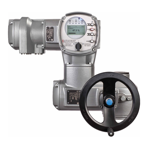
Part-turn actuators
SGExC 05.1
SGExC 12.1
Control unit: electromechanic
with actuator controls
AUMATIC ACExC 01.2 Intrusive
Control
Parallel
Profibus DP
Modbus
Foundation Fieldbus
Operation instructions
Assembly, operation, commissioning
Table of
Contents
Previous
Page
Next
Page
1
2
3
4
5
Advertisement
Table of Contents
Need help?
Do you have a question about the SGExC 05.1 and is the answer not in the manual?
Ask a question
Questions and answers
Related Manuals for AUMA SGExC 05.1
Controller AUMA SGExC 05.1 Operation Instructions Manual
Part-turn (80 pages)
Control Unit AUMA AC 01.2 Manual
Actuator controls (160 pages)
Control Unit AUMA AC 01.2 Manual
Actuator controls (148 pages)
Controller AUMA SQEx 05.2 Operating Instructions Manual
Part-turn actuators. control unit: electronic (mwg) with actuator controls. acexc 01.2 non-intrusive (112 pages)
Controller AUMA SQEx 05.2 Operation Instructions Manual
Part-turn actuators, control unit - electromechanical with actuator controls (108 pages)
Control Unit AUMA AUMATIC AC 01.2 Manual
Profibus dp actuator controls (92 pages)
Controller AUMA AUMATIC AC 01.2 Manual
(81 pages)
Controller AUMA AUMATIC AC 01.2 Manual
Actuator controls foundation fieldbus (60 pages)
Controller AUMA FQM 05.1 Manual
(44 pages)
Controller AUMA SA 07.2 Manual
Multi-turn actuators with actuator controls sfc version (24 pages)
Controller AUMA SG 05.1 Operation Instructions Manual
Control unit: electronic (mwg) with actuator controls aumatic ac 01.1 non-intrusive (80 pages)
Controller AUMA SG 05.1-F05 Operating Instructions Manual
Part-turn actuators sg series; sgr series. with actuators. auma matic am 01.1 (68 pages)
Controller AUMA NORM Series Operation Instructions Manual
Electric part-turn actuators (28 pages)
Controller AUMA SG 07.1 Operation Instructions Manual
Quarter-turn actuators (17 pages)
Controller AUMA SG 10.1 Operation Instructions Manual
Quarter-turn actuators (17 pages)
Controller AUMA SGM 04.1 Operation Instructions Manual
Part-turn actuators (52 pages)
This manual is also suitable for:
Sgexc 07.1
Sgexc 10.1
Sgexc 12.1
Sgexc 05.1-f05
Sgexc 05.1-f07
Sgexc 07.1-f07
...
Show all
Sgexc 07.1-f10
Sgexc 10.1-f10
Sgexc 10.1-f12
Sgexc 12.1-f12
Sgexc 12.1-f14
Sgexc 12.1-f16
Aumatic acexc 01.2 intrusive
Table of Contents
Save PDF
Print
Rename the bookmark
Delete bookmark?
Delete from my manuals?
Login
Sign In
OR
Sign in with Facebook
Sign in with Google
Upload manual
Upload from disk
Upload from URL


Need help?
Do you have a question about the SGExC 05.1 and is the answer not in the manual?
Questions and answers