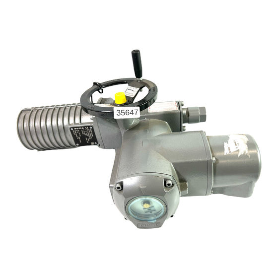
1. EQUIPMENT DESCRIPTION AUMA quarter-turn actuators are high quality electro-mechanical devices. The AUMA Model SG is a quarter turn electric actuator, designed in accordance with AWWA Standards. Four sizes are available: Output Torque Range Model (Ft.-Lbs.) SG 05.1 66-110 SG 07.1 88-220 SG 10.1...
3. SERVICE CONDITIONS AUMA quarter-turn actuators can be used at following ambient conditions: Model Temperature SG 05.1 – 12.1 1-Phase -20°F to +160°F SG 05.1 – 12.1 3-Phase -20°F to +175°F For other conditions, consult factory. 4. MOUNTING TO THE VALVE/GEARBOX Mounting and operation can be in any position.
• Connect control wires to designated terminals in accordance with drawing. CAUTION: The following must be considered when wiring an AUMA actuator: ♦ The time delay (i.e., from limit or torque switch tripping until the motor is switched off) should not exceed 20 ms.
♦ AUMA motors have thermoswitches as standard equipment. These switches must be directly wired into the control circuit to protect the motor. If these are not connected, the warranty for the motor is not valid. Completion of Electrical Connection • Clean the sealing faces at plug or cover for terminal compartment, check to ensure that the O-ring is not damaged.
8. SETTING OF LIMIT SWITCHING Setting the Closed Limit Switch (LSC) To set limit switch LSC, refer to Figures 1 and 2, and complete the setting instructions below. NOTE: If the SG is not mounted to a valve when received, stop housing retainer plate bolts (03) are loose.
THE OPEN END STOP IS FACTORY SET, AND SHOULD NOT NEED ADJUSTMENT. AUMA SG Actuators may be set for 80° to 110° of rotation, by repositioning the open end stop. To adjust the open end stop, refer to Figure 1, and complete the following instructions:...
• Install the cover and tighten. 13. OPTIONAL EQUIPMENT AUMA SG Actuators equipped with four gear train limit switches, LSA and LSB, may be set for valve mid-position control signaling. LSA may be set to trip at a selected valve position as the actuator is operated in the closing (CW) direction.
Setting Limit Switch LSB • Rotate the handwheel to locate the valve in a mid-position. • Rotate the handwheel counter-clockwise to position the valve at the desired LSB tripping point, and back-off (clockwise) four (4) full turns. • Apply the setting instructions as outlined in Section 7 to set limit switch LSB using Spindle K, Pointer L and Point F.
14. STORAGE The following are short-term storage instructions (Less than 12 Months): • Actuators should be stored in a clean, dry, protected environment, free from excessive vibration and rapid temperature changes. If actuators must be stored outdoors, they must be stored high enough off the ground to prevent being immersed in water or buried in snow.
Limit switches do not function - valve torques out at either end, and indicator disc does not operate. Problem: Limit switch drive arm broken or bent (part number 21). Solution: Contact AUMA representative. Symptom: Valve will not turn with motor running, but operates manually. Problem: Damaged planetary gear set.
Page 17
For professional start-up and reliable service in the field, AUMA has factory specialists for: • Shipping of original spare parts • Commissioning • Maintenance/repair • Trouble-shooting assistance Before calling for our support, please have the following information 1) For Parts: —...
Need help?
Do you have a question about the SG 05.1 and is the answer not in the manual?
Questions and answers