
Subscribe to Our Youtube Channel
Related Manuals for AUMA SGM Series


Summary of Contents for AUMA SGM Series
- Page 1 Part-turn actuators SGM 04.1 SGM 12.1 SGMR 04.1 SGMR 12.1 with integral actuator controls Control Parallel Profibus DP Modbus Operation instructions Assembly, operation, commissioning...
-
Page 2: Table Of Contents
This document contains information for installation, commissioning, operation and maintenance staff. It is intended to support device installation and commissioning. Reference documents: Reference documents can be downloaded from the Internet (www.auma.com) or ordered directly from AUMA (refer to <Addresses>). Table of contents Page Safety instructions......................... - Page 3 10.3.2. End position OPEN: set again 10.4. Switch compartment: open 10.5. Mechanical position indicator: set 10.6. Switch compartment: close AUMA CDT software (accessories)..................Corrective action........................12.1. Fault indications and warning indications 12.2. Fuses 12.2.1. Fuses within the actuator controls 12.2.2.
-
Page 4: Safety Instructions
Any device modification requires prior consent of the manufacturer. 1.2. Range of application AUMA part-turn actuators are designed for the operation of valves, e.g. butterfly valves and ball valves. Other applications require explicit (written) confirmation by the manufacturer. The following applications are not permitted, e.g.:... -
Page 5: Warnings And Notes
SGM 04.1 SGM 12.1 / SGMR 04.1 SGMR 12.1 Safety instructions Escalators Buried service Continuous submersion (observe enclosure protection) Potentially explosive atmospheres Radiation exposed areas in nuclear power plants No liability can be assumed for inappropriate or unintended use. Observance of these operation instructions is considered as part of the device's designated use. - Page 6 SGM 04.1 SGM 12.1 / SGMR 04.1 SGMR 12.1 Safety instructions < > Reference to other sections Terms in brackets shown above refer to other sections of the document which provide further information on this topic. These terms are either listed in the index, a heading or in the table of contents and may quickly be found.
-
Page 7: Identification
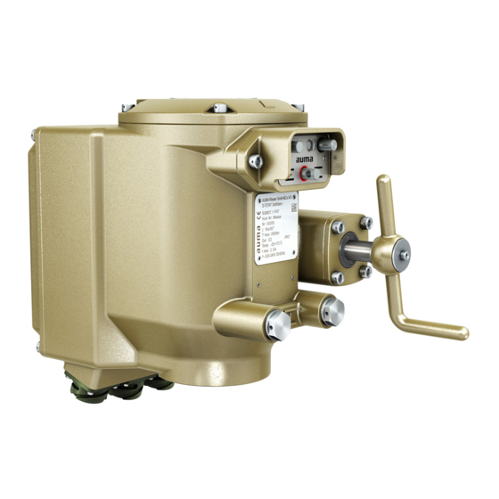
SGM 04.1 SGM 12.1 / SGMR 04.1 SGMR 12.1 Identification Identification 2.1. Name plate Figure 1: Arrangement of name plates Actuator name plate Additional plate, e.g. KKS plate (Power Plant Classification System) Description of actuator name plate Figure 2: Actuator name plate (example) Name of manufacturer Address of manufacturer Type designation (see explanation below) -
Page 8: Short Description
AUMA CDT The AUMA CDT software (accessories) can be used to establish a connection to a computer (PC, laptop or PDA). Among others, the software can be used to read in and out data and to save and modify settings. -
Page 9: Transport, Storage And Packaging
SGM 04.1 SGM 12.1 / SGMR 04.1 SGMR 12.1 Transport, storage and packaging Transport, storage and packaging 3.1. Transport For transport to place of installation, use sturdy packaging. Hovering load! Risk of death or serious injury. Do NOT stand below hovering load. Attach ropes or hooks for the purpose of lifting by hoist only to housing and NOT to handwheel. -
Page 10: Assembly
SGMR 12.1 Assembly Assembly 4.1. Mounting position AUMA actuators can be operated without restriction in any mounting position. 4.2. Actuator: mount to valve 4.2.1. Actuator for assembly: prepare Prior to mounting, both valve and actuator must be in the same end position! For butterfly valves, the recommended mounting position is end position CLOSED. -
Page 11: 4.2.2.1. Mounting With Coupling
SGM 04.1 SGM 12.1 / SGMR 04.1 SGMR 12.1 Assembly Figure 4: Coupling variants Bore with keyway Square bore Bore with two-flats Valve shaft Output drive flange (size 12.1) 4.2.2.1. Mounting with coupling Condition: Valve and actuator are in the same end position. Figure 5: Coupling fitting dimensions Coupling Valve shaft... - Page 12 SGM 04.1 SGM 12.1 / SGMR 04.1 SGMR 12.1 Assembly If flange bores do not match thread: 6.1 Slightly rotate handwheel until bores line up. 6.2 If required, shift actuator position by one tooth on the coupling. Fasten actuator with screws [4]. Information: We recommend applying liquid thread sealing material to the screws to avoid contact corrosion.
-
Page 13: Electrical Connection
The pertaining wiring diagram/terminal plan (in German and English language) is plan attached to the device in a weather-proof bag, together with these operation instructions. It can also be obtained from AUMA (state commission no., refer to name plate) or downloaded directly from the Internet (www.auma.com). Permissible networks... -
Page 14: Connection Via Bayonet Connector
SGM 04.1 SGM 12.1 / SGMR 04.1 SGMR 12.1 Electrical connection For the connection of remote position transmitters, screened cables must be used. Type of current, mains Type of current, mains voltage and mains frequency must match the data on the voltage and mains fre- motor name plate. -
Page 15: Cable Connection
Observe permissible cross sections. Use suitable crimping tools, such as Cannon four indent crimp tool. For connecting cables, AUMA offer a suitable plug and socket assembly (AUMA article number Z049.356), consisting of a 5-pin power plug and one 19-pin signal plug. -
Page 16: Indications
SGM 04.1 SGM 12.1 / SGMR 04.1 SGMR 12.1 Indications Indications 6.1. Mechanical position indicator/running indication Mechanical position indicator: Continuously indicates the valve position (For a swing angle of 90°, the indicator disc [2] rotates by approximately 90°.) Indicates whether the actuator is running (running indication) Indicates that the end positions are reached (via indicator mark [3]) Figure 9: Mechanical position indicator Cover... - Page 17 SGM 04.1 SGM 12.1 / SGMR 04.1 SGMR 12.1 Indications Colour/state Signification Description blinking in blue LOCAL Operation mode LOCAL is active. The actuator can be (1 Hz) operated via push buttons. blinking in blue Set end position Setting mode for end position setting is active. (5 Hz)
-
Page 18: Signals
Rated power: 24 V DC, 1A Switches: 1 NO (standard) Default values: Designation of output contacts in Designation of output contact in AUMA CDT soft- wiring diagram ware K 1 = End position CLOSED Signal DOUT 1 = End position CLOSED... -
Page 19: Operation
SGM 04.1 SGM 12.1 / SGMR 04.1 SGMR 12.1 Operation Operation 8.1. Manual operation For purposes of setting and commissioning, in case of motor failure or power failure, the actuator may be operated manually. The handwheel does not rotate during motor operation. Change-over from motor operation to manual operation is not required. -
Page 20: Actuator Operation From Remote
Push-to-run operation or self-retaining is set via the controls software. Refer to <AUMA CDT software (accessories)> chapter. It is possible to temporarily (for one operation command) activate self-retaining by means of the push buttons: → Press and hold down push buttons OPEN [1] or CLOSE [3] for more than 3 seconds. - Page 21 SGM 04.1 SGM 12.1 / SGMR 04.1 SGMR 12.1 Operation Figure 13: Local controls Operation mode LOCAL/REMOTE Indication light for operation mode LOCAL (blue) Activate operation mode Remote by means of local controls: If indication light [4] is blinking in blue: Hold down push button [2] for approx. 3 seconds until the blue indication light goes out.
-
Page 22: Commissioning (Basic Settings Of Controls)
AUMA CDT software (accessories); By connecting a PC, laptop or PDA. Also refer to <AUMA CDT software (accessories)> chapter. Please also refer to <AUMA CDT software (accessories)> chapter for further settings. 9.1. Cover to controls: open The cover to the integral controls must be opened to perform the following settings (options). -
Page 23: Type Of Seating: Set
Hardware mode (factory setting on delivery) Settings of switches [S2] through [S4] and [S6] through [S10] are valid. The values cannot be changed via AUMA CDT software. Software mode (sliding switch at white dot) Settings of switches [S2] through [S4] and [S6] through [S10] are NOT relevant. -
Page 24: Torque Switching: Set
04.1 05.1 07.1 10.1 12.1 1,000 1,000 Setting via software parameters (AUMA CDT) Condition: Switch [S5] is in position ON (software mode). Setting parameters Customer settings Torque switching Tripping torque CLOSE (S7) Tripping torque OPEN (S6) Default value: depending on the order... -
Page 25: Operating Time: Set
Motor is operating in stepping mode Setting via software parameters (AUMA CDT) Motor speed and thus actuator operating time can be modified by means of the software parameters described below. Contrary to operating time setting using switch... - Page 26 SGM 04.1 SGM 12.1 / SGMR 04.1 SGMR 12.1 Commissioning (basic settings of controls) Motor speed Speed LOCAL Speed REMOTE Speed I/O interface Description of parameters: Output speed for operation via local controls (operation mode Local); Setting range: Speed LOCAL linear between 0 100 % of max.
-
Page 27: Cover To Controls: Close
SGM 04.1 SGM 12.1 / SGMR 04.1 SGMR 12.1 Commissioning (basic settings of controls) Output speed via parameter: Output speed via AIN1 Output speed Operating time Speed LOCAL (Speed I/O interface = External) Motor Output drive Speed REMOTE [rpm] [rpm] 20 mA 20 mA 38.0 %... -
Page 28: Commissioning (Basic Settings At Actuator)
SGM 04.1 SGM 12.1 / SGMR 04.1 SGMR 12.1 Commissioning (basic settings at actuator) Commissioning (basic settings at actuator) 10.1. End stops in part-turn actuator The internal end stops limit the swing angle. They protect the valve in the event of limit switching failure. -
Page 29: End Stop Closed: Set
SGM 04.1 SGM 12.1 / SGMR 04.1 SGMR 12.1 Commissioning (basic settings at actuator) Figure 19: End stop, size SGM 12.1 Screw plug for end stop OPEN Setting screw for end stop OPEN Screw plug for end stop CLOSED Setting screw for end stop CLOSED Dimen- 04.1 05.1... -
Page 30: End Position Detection: Verify Setting
SGM 04.1 SGM 12.1 / SGMR 04.1 SGMR 12.1 Commissioning (basic settings at actuator) If the valve end position is not reached: Slightly turn setting screw [2] counterclockwise until valve end position OPEN can be safely set. Turning the setting screw [2] clockwise results in a smaller swing angle. Turning the setting screw [2] counterclockwise results in a larger swing angle. -
Page 31: End Position Closed: Set Again
SGM 04.1 SGM 12.1 / SGMR 04.1 SGMR 12.1 Commissioning (basic settings at actuator) Activate operation mode LOCAL: Hold down push button [2] for approx. 3 seconds until right indication light is blinking in blue. Information If the local controls are not provided on site, it is possible to connect an external control module. -
Page 32: End Position Open: Set Again
SGM 04.1 SGM 12.1 / SGMR 04.1 SGMR 12.1 Commissioning (basic settings at actuator) 10.3.2. End position OPEN: set again Activate setting mode "end position setting": Press push button [2] hold down and press push buttons [1] and [3] at the same time. -
Page 33: Mechanical Position Indicator: Set
SGM 04.1 SGM 12.1 / SGMR 04.1 SGMR 12.1 Commissioning (basic settings at actuator) 10.5. Mechanical position indicator: set Move valve to end position CLOSED. Turn lower indicator disc until symbol (CLOSED) is in alignment with the mark on the cover. Move actuator to end position OPEN. -
Page 34: Auma Cdt Software (Accessories)
Z100.999) is required. Read/perform basic settings via AUMA CDT Basic settings at the device (in controls) made via switches are read only via AUMA CDT on delivery and cannot be modified. To be able to change these parameters via software, position switch [S5] in controls to "Software mode". -
Page 35: Corrective Action
5 blinks Fault indication 5 Fault E2 (actual value of positioner) → Check wiring (for possible loss of signal) of → Read detailed fault indication via AUMA CDT software (accessories). 6 blinks Fault indication 6 Actuator is outside the permissible position (potentiometer signal). -
Page 36: Fuses
For reasons of accuracy, we recommend se- lection of the stroke higher than 60 % of the maximum turn range. → Abort warning: Set again Low limit Uspan parameter via AUMA CDT software within the Position transmitter potentiometer sub-menu. 12.2. Fuses 12.2.1. -
Page 37: Servicing And Maintenance
Only perform servicing and maintenance tasks when the device is switched off. AUMA AUMA offer extensive service such as servicing and maintenance as well as customer Service & Support product training. For the relevant contact addresses, please refer to <Addresses>... -
Page 38: Technical Data
The following technical data includes standard and optional features. For detailed information on the customer-specific version, refer to the order-relevant data sheet. This data sheet can be downloaded from the Internet at http://www.auma.com in German and English (indication of commission number required). -
Page 39: Features And Functions Of Actuator Controls
SGM 04.1 SGM 12.1 / SGMR 04.1 SGMR 12.1 Technical data 14.3. Features and functions of actuator controls Power supply For mains voltage and frequency, refer to the name plate Permissible variation of mains voltage: ±10 % Permissible variation of mains frequency: ±5 % For current consumption, refer to name plate External supply of the electron- 24 V DC +20 % / 15 %... -
Page 40: Service Conditions
Corrosion protection Sea water resistant bronze housing. The output drive unit of SGM/SGMR 12.1 is made of GJL, powder coated and meets the requirements of AUMA corrosion protection KS. All ex- ternal screws and shafts are of stainless steel. Suitable for installation in industrial units, in water or power plants with a... -
Page 41: Spare Parts
SGM 04.1 SGM 12.1 / SGMR 04.1 SGMR 12.1 Spare parts Spare parts 15.1. Part-turn actuators SGM 04.1 SGM 12.1/SGMR 04.1 SGMR 12.1... - Page 42 Information: Please state type and commission no. of the device (see name plate) when ordering spare parts. Only original AUMA spare parts should be used. Failure to use original spare parts voids the warranty and exempts AUMA from any liability. Delivered spare parts may slightly vary from the representation.
-
Page 43: Certificates
SGM 04.1 SGM 12.1 / SGMR 04.1 SGMR 12.1 Certificates Certificates 16.1. Declaration of Incorporation and EC Declaration of Conformity... -
Page 44: Index
Indicator disc 16 , 33 Ambient temperature 7 , 40 Inspection record Analogue signals Insulation class Applications Assembly AUMA CDT (accessories) 8 , 34 LEDs (indication lights) Lifetime Limit switching Basic setting 28 , 34 Local controls Basic settings for controls... - Page 45 SGM 04.1 SGM 12.1 / SGMR 04.1 SGMR 12.1 Index Qualification of staff Year of manufacture Year of production Range of application Rated current Recycling Remote actuator operation Running indication Safety instructions Safety instructions/warnings Self-locking Self-retaining local 20 , 34 Serial number 7 , 8 Service...
-
Page 46: Addresses
IBEROPLAN S.A. AUMA Polska Sp. z o.o. ES 28027 Madrid PL 41-219 Sosnowiec Tel +34 91 3717130 Tel +48 32 783 52 00 AUMA Riester GmbH & Co. KG iberoplan@iberoplan.com biuro@auma.com.pl www.auma.com.pl Plant Müllheim OY AUMATOR AB DE 79373 Müllheim... - Page 47 Tel + 673 3331269 / 3331272 Tel +968 24 636036 AUMA Argentina Rep.Office mikuni@brunet.bn r-negi@mustafasultan.com AR Buenos Aires Tel +54 11 4737 9026 AUMA Actuators (Tianjin) Co., Ltd. Beijing FLOWTORK TECHNOLOGIES contacto@aumaargentina.com.ar Branch CORPORATION CN 100020 Beijing PH 1550 Mandaluyong City AUMA Automação do Brazil ltda.
- Page 48 AUMA Riester GmbH & Co. KG P.O.Box 1362 DE 79373 Muellheim Tel +49 7631 809 - 0 Fax +49 7631 809 - 1250 riester@auma.com www.auma.com Y004.840/003/en/3.13 For detailed information on AUMA products refer to the Internet: www.auma.com...
Need help?
Do you have a question about the SGM Series and is the answer not in the manual?
Questions and answers