Table of Contents
Advertisement
Advertisement
Table of Contents

Subscribe to Our Youtube Channel
Related Manuals for AUMA NORM Series


Summary of Contents for AUMA NORM Series
- Page 1 Electric part-turn actuators SG 03.3 – SG 04.3 AUMA NORM Operation instructions...
-
Page 2: Table Of Contents
Checking the end stops Setting of end stop CLOSED Setting of end stop OPEN Setting values for mechanical end stops Electrical connection Connection with AUMA plug/ socket connector Heater Motor protection Remote position transmitter Limit switch Fitting of the cover Setting the limit switching 10.1... -
Page 3: Safety Instructions
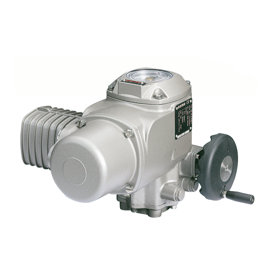
Setting must be checked during commissioning! Short description AUMA part-turn actuators type SG 03.3 – SG 04.3. have a modular design. Manual operation is possible without change-over. The limitation of travel is realised via limit switches in both end positions. -
Page 4: Technical Data
110 – 250 V DC/AC or 24 – 48 V DC/AC Option: Resistance type heater, 5 W, 24 V DC (only in combination with the AUMA controls AM or AC) Manual operation Manual drive for setting and emergency operation, handwheel does not rotate during... -
Page 5: Transport And Storage
Part-turn actuators SG 03.3 – SG 04.3 Operation instructions AUMA NORM Transport and storage Transport to place of installation in sturdy packing. Do not attach ropes or hooks to the handwheel for the purpose of lifting by hoist. If part-turn actuator is mounted on valve, attach ropes or hooks for the purpose of lifting by hoist to valve and not to part-turn actuator. -
Page 6: Mounting To Valve
Part-turn actuators SG 03.3 – SG 04.3 AUMA NORM Operation instructions Mounting to valve Prior to mounting the part-turn actuator must be checked for any damage. Damaged parts must be replaced by original spare parts. After mounting to valve, touch up any possible damages to paint finish. -
Page 7: Checking The End Stops
Part-turn actuators SG 03.3 – SG 04.3 Operation instructions AUMA NORM Checking the end stops This check can only be performed on valves which are not yet mounted into a pipeline. Setting of end stop CLOSED Check whether mechanical end position of the valve corresponds to the... -
Page 8: Setting Of End Stop Open
Part-turn actuators SG 03.3 – SG 04.3 AUMA NORM Operation instructions Setting of end stop OPEN The swing angle has been set in the factory to approx. 90° or to the swing angle stated in the order. An adjustment might be necessary if the end stop CLOSED has been re-adjusted. -
Page 9: Electrical Connection
In case the wiring diagram is not available, it can be obtained from AUMA (state com- Figure C2: Parking frame (accessory) mission no., refer to name plate) or downloaded directly from the Internet... -
Page 10: Remote Position Transmitter
Part-turn actuators SG 03.3 – SG 04.3 AUMA NORM Operation instructions Remote position transmitter For the connection of position transmitters (potentiometer, RWG) screened cables must be used. Limit switch Only the same potential can be switched on the two circuits (NC/ NO con- tact) of each single switch. -
Page 11: Setting The Limit Switching
Part-turn actuators SG 03.3 – SG 04.3 Operation instructions AUMA NORM 10. Setting the limit switching Take off cover at switch compartment. Pull off indicator disc (figure D). Open end spanner (approx. 14 mm) may be used as lever. Figure D Indicator disc These operation instructions are only valid for “clockwise closing”, i.e. -
Page 12: Setting For End Position Open (White Section)
Part-turn actuators SG 03.3 – SG 04.3 AUMA NORM Operation instructions 10.2 Setting for end position OPEN (white section) Turn handwheel counter-clockwise until valve is open. Turn handwheel approx. 1 turn in direction CLOSE and then half a turn in direction OPEN. -
Page 13: Setting Of The Potentiometer (Option)
Part-turn actuators SG 03.3 – SG 04.3 Operation instructions AUMA NORM 13. Setting of the potentiometer (option) – For remote indication – Move valve to end position CLOSED. Take off cover at switch compartment. Pull off indicator disc. Turn potentiometer (R) counter-clockwise until stop is felt. End position CLOSED corresponds to 0 %, end position OPEN to 100 %. -
Page 14: Setting Of 2-Wire System 4 - 20 Ma And 4-Wire System 0 - 20 Ma
0 mA, for 2-wire system it must be 4 mA. The circuit (external load) must be connected (observe max. ext. load R ), or the appropriate poles at the AUMA plug/ socket connector must be linked (refer to terminal plan), otherwise no value can be measured. -
Page 15: Setting Of 4-Wire System 4 - 20 Ma
MP2) (figure J). The circuit (external load) must be connected (observe max. ext. load R ), or the appropriate poles at the AUMA plug/ socket connector must be linked (refer to terminal plan), otherwise no value can be measured. Turn potentiometer (R, figure H) counter-clockwise until stop is felt. -
Page 16: Setting Of The Electronic Intermediate Position Detection (Option)
Part-turn actuators SG 03.3 – SG 04.3 AUMA NORM Operation instructions 15. Setting of the electronic intermediate position detection (option) Any application can be switched on or off via the two intermediate position switches WDR/LSA and WDL/LSB. The intermediate position detection is set in the factory according to order details. -
Page 17: Maintenance
The gear housing is filled with lubricant in the factory. This filling lasts for several years of service. 17. Disposal and recycling AUMA actuators have an extremely long lifetime. However, there will come a time when you have to replace them. Our actuators have a modular design and may therefore easily be disas- sembled, separated and sorted according to materials, i.e.:... -
Page 18: Proposed Wiring Diagrams
Limit switch, opening, counter-clockwise rotation F 1/ TH Thermoswitch (motor protection) R 1 / H Heater R 2 / f1 Potentiometer S 12 Local control switch OPEN – STOP – CLOSE Customer connection at the AUMA plug/ socket connector Capacitor (1 or 2 pieces) -
Page 19: Wiring Diagram For Sg With 1-Phase Ac Motors
Part-turn actuators SG 03.3 – SG 04.3 Operation instructions AUMA NORM 19.1 Wiring diagram for SG with 1-phase AC motors (Legend page 18) -
Page 20: Wiring Diagram For Sg With 1-Phase Ac Motors With Reversing Contactor Controls
Part-turn actuators SG 03.3 – SG 04.3 AUMA NORM Operation instructions 19.2 Wiring diagram for SG with 1-phase AC motors with reversing contactor controls (Legend page 18) -
Page 21: Wiring Diagram For Sg With 3-Phase Ac Motors
Part-turn actuators SG 03.3 – SG 04.3 Operation instructions AUMA NORM 19.3 Wiring diagram for SG with 3-phase AC motors (Legend page 18) -
Page 22: Spare Parts List Part-Turn Actuator Sg 03.3 - Sg
Part-turn actuators SG 03.3 – SG 04.3 AUMA NORM Operation instructions 20. Spare parts list part-turn actuator SG 03.3 – SG 04.3... - Page 23 Part-turn actuators SG 03.3 – SG 04.3 Operation instructions AUMA NORM Note: When placing your order for spare parts , please mention type of part-turn actuator and our commission number (refer to name plate). Type Designation Type Designation Capacitor Screw plug Capacitor 17.
- Page 24 Part-turn actuators SG 03.3 – SG 04.3 AUMA NORM Operation instructions Notes...
- Page 25 Part-turn actuators SG 03.3 – SG 04.3 Operation instructions AUMA NORM Notes...
-
Page 26: Declaration Of Conformity And Declaration Of Incorporation
Part-turn actuators SG 03.3 – SG 04.3 AUMA NORM Operation instructions 21. Declaration of Conformity and Declaration of Incorporation... -
Page 27: Index
Test run Thermoswitch Transport Information also available Terminal plan, inspection records and further actuator information can be downloaded directly from the internet by entering the order no. or on the Internet: comm no. (refer to name plate).. Our homepage: http://www.auma.com... -
Page 28: Adresses Auma Offices And Representatives
+49 7631 - 809-0 +49 711 - 34803 0 Certificate Registration No. +49 7631 - 809 1250 +49 711 - 34803 34 12 100/104 4269 riester@auma.com riester@wof.auma.com www.auma.com www.auma.com For detailed information about AUMA products refer to the Internet: Y000.777/003/en/1.04 www.auma.com...
Need help?
Do you have a question about the NORM Series and is the answer not in the manual?
Questions and answers