Otto Bock 17KO1 Series Instructions For Use Manual
C-brace joint unit
Hide thumbs
Also See for 17KO1 Series:
- Instructions for use manual (108 pages) ,
- Instructions for use manual (116 pages) ,
- Instructions for use manual (48 pages)

Related Manuals for Otto Bock 17KO1 Series


Summary of Contents for Otto Bock 17KO1 Series
- Page 1 C-Brace joint unit 17KO1=* Instructions for use (qualified personnel) ..............
- Page 2 DE | INFORMATION Zusätzlich zu der gedruckten Gebrauchsanweisung, sind auch weitere Sprachen auf CD beigelegt (siehe rückseitigen Umsch lag). Auf Anfrage können Sie eine gedruckte Gebrauchsanweisung kostenlos in der jeweiligen Landessprache unter der unten angegebenen Anschrift bestellen. EN | INFORMATION In addition to the printed Instructions for Use, additional language versions are also included on CD (see back cover).
- Page 3 Ottobock Healthcare Products GmbH Brehmstraße 16 | 1110 Wien | Austria Service-admin.vienna@ottobock.com | Fax (+43-1) 526 79 85 C-Brace joint unit 17KO1=*...
- Page 4 C-Brace joint unit 17KO1=*...
-
Page 5: Table Of Contents
Table of contents Table of contents Foreword ................................Product description ............................Design ..............................2.1.1 Control panel on the joint unit ......................... Function .............................. Combination possibilities ........................Application ................................. Indications for use ..........................Conditions of use ..........................Indications ............................Contraindications ..........................3.4.1 Absolute Contraindications ........................ - Page 6 Table of contents MyModes ............................8.9.1 Basic mode ............................8.9.2 MyMode "Training mode" ........................8.9.3 MyMode "Freeze position" ........................8.9.4 MyMode "User defined" ........................8.10 Preferences ............................8.11 Configuration of the Cockpit app ......................8.12 Data overview ............................. 8.13 Navigation menu of the adjustment app ....................
- Page 7 Table of contents Additional operating states (modes) ......................12.1 Empty battery mode ..........................12.2 Mode for charging the product ......................12.3 Safety mode ............................12.4 Overheating mode ..........................Cleaning ................................Maintenance ..............................Legal information .............................. 15.1 Liability .............................. 15.2 Local Legal Information ........................
-
Page 8: Foreword
Only put the product into use in accordance with the information contained in the accompanying documents sup plied. According to the manufacturer (Otto Bock Healthcare Products GmbH), the patient is the operator of the product according to the IEC 60601-1:2005/A1:2012 standard. -
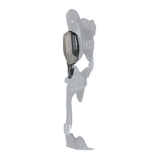
Page 9: Control Panel On The Joint Unit
Product description 2.1.1 Control panel on the joint unit Long button press: turns the component on/off (see Page 41) Short button press: queries the status (see Page 51) Displays the charge level of the integrated battery (see Page 22) Maintenance required (see Page 51) Long button press: turns the Bluetooth function on/off (see Page 42). -
Page 10: Application
Application < 55 kg 55 - 85 kg 85 - 110 kg 110 - 125 kg Unilateral ankle 17AO100 17AO100 17AO100 – joint 17LA3N=20 – – – Bilateral ankle joint 17AO100 17AO100 17AO100 17AO100 17LA3N=20 17LA3N=20 17LA3N=20 – 17LA3N=16 17LA3N=16 – – The following possible combinations are recommended < 55 kg 55 - 85 kg 85 - 110 kg... -
Page 11: Safety
Safety 4 Safety 4.1 Explanation of warning symbols Warning regarding possible serious risks of accident or injury. WARNING Warning regarding possible risks of accident or injury. CAUTION Warning regarding possible technical damage. NOTICE 4.2 Structure of the safety instructions WARNING The heading describes the source and/or the type of hazard The introduction describes the consequences in case of failure to observe the safety instructions. - Page 12 Safety CAUTION Independent manipulations on the joint unit and orthosis components Falling due to the breakage of load-bearing components or malfunction of the orthosis. ► Manipulations on the joint unit and orthosis components other than the tasks described in these instructions for use are not permitted.
-
Page 13: Information On The Power Supply/Battery Charging
Safety 4.4 Information on the Power Supply/Battery Charging CAUTION Charging the product with damaged power supply unit/charger/charger cable Falling due to unexpected behaviour of the product caused by insufficient charging. ► Check the power supply unit, charger and charger cable for damage before use. ►... -
Page 14: Information On Alignment/Adjustment
Safety 4.6 Information on Alignment/Adjustment CAUTION Improper assembly of the screw connections Falling due to breakage or loosening of the screw connections. ► Clean the threads before every installation. ► Apply the specified tightening torque values for installation (see the section "Technical data"). ►... -
Page 15: Notes On Applying The Product
Safety 4.7 Notes on applying the product CAUTION Foreign objects between the leg and orthosis shells Pressure points on the leg due to foreign objects at the contact points between the leg and orthosis shells. ► Smooth out wrinkles in the padding material and clothing. ►... -
Page 16: Information On Use
Safety CAUTION Entering a room or area with strong magnetic fields (e.g. magnetic resonance tomographs, MRT (MRI) equipment...) > Falling due to unexpected restriction of the product's range of motion caused by metallic objects adhering to the magnetised components. > Irreparable damage to the product due to the effect of strong magnetic fields. -
Page 17: Notes On The Movement Patterns
Safety CAUTION Overloading due to unusual activities > Falling due to unexpected product behaviour as the result of a malfunction. > Falling due to breakage of load-bearing components. > Skin irritation due to defects on the hydraulic unit with leakage of liquid. ►... - Page 18 Safety CAUTION Walking down stairs and ramps Falling due to unexpected, increased stance phase damping during the transition from walking on the level to stairs or ramps, for example when the orthosis is in a MyMode. ► Inform the patient of the changed product behaviour, especially in the MyModes. ►...
-
Page 19: Notes On The Safety Modes
Safety 4.11 Notes on the safety modes CAUTION Safety mode cannot be activated due to malfunction caused by water penetration or mechanical damage Falling due to unexpected product behaviour because of changed damping behaviour. ► Using the product when it is defective is prohibited. ►... -
Page 20: Scope Of Delivery And Accessories
Scope of Delivery and Accessories NOTICE Destruction of the mobile device due to falling or penetration of water Malfunction of the mobile device. ► If necessary, let the mobile device dry at room temperature (at least 1 day). ► Should it no longer be possible to switch back from a MyMode to basic mode, the component can only be switched back to basic mode by turning it off/on (see Page 41). -
Page 21: Connecting The Power Supply And Battery Charger
Charging the battery • Switching the MyModes and changing setting parameters using the Cockpit app is not possible during the charging process. • After disconnecting the battery charger, the orthosis is in the same state it was in before connecting the battery charger. -
Page 22: Display Of The Current Charge Level
Charging the battery INFORMATION No display after connecting the battery charger If no symbols light up on the control panel after connecting the battery charger, the battery may be deep dis charged. Leave the battery charger connected for at least 15 minutes and check the charge level while charging by pressing the button. -
Page 23: Preparation For Use
Preparation for use 7 Preparation for use 7.1 Assembling/disassembling the joint unit on the orthosis Assembling the joint unit on the orthosis (see fig. 9) CAUTION Reusing the screws to assemble the joint unit on the frame after maintenance Falling due to breakage of screws that are reused to assemble the joint unit. ►... -
Page 24: C-Brace Setup" Adjustment App
"C-Brace Setup" adjustment app 8 "C-Brace Setup" adjustment app The "C-Brace Setup" adjustment app makes it possible to optimise the product settings for a patient. The adjustment app provides step-by-step guidance through the adjustment pro cess. After the settings are configured, the settings data can be exported in PDF format. The adjustment app is also used for configuration of the Cockpit app. -
Page 25: Establishing The Connection Between The Adjustment App And Component
"C-Brace Setup" adjustment app Logging in with a previously saved password 1) Tap the "C-Brace Setup" ( ) symbol. → The login screen is displayed. 2) Enter the username and password in the "User name" and "Password" fields. The last 5 users who logged in on this tablet can also be chosen from the list that is displayed during input. -
Page 26: Entering Patient Data
"C-Brace Setup" adjustment app 1) Tap the symbol in the top left corner to open the navigation menu. 2) Tap the "App settings" menu item. → The unit settings menu is displayed. 3) Tap the setting in question. 4) Tap the "OK" button to save the setting and close the navigation menu. 8.5 Entering patient data After each input, a confirmation signal is emitted by the component to confirm the successful transfer of the values. -
Page 27: Stance Phase
"C-Brace Setup" adjustment app If the prerequisites listed in the adjustment app are not met, the corresponding deviations are displayed. Only after the deviations are corrected can the calib ration be started. • The patient is not standing still The patient should be standing as still as possible. The support of parallel bars may help. -
Page 28: Optimisation While Walking On The Level
"C-Brace Setup" adjustment app Intuitive locking of the joint The intuitive stance function recognises any situation that puts strain on the orthosis in the flexion direction but where flexion is not permitted. Examples of this include standing on uneven or sloping surfaces. The joint is always locked in the flexion direction when the leg with the orthosis is not fully extended and is kept still for a brief moment. -
Page 29: Mymode "Freeze Position
"C-Brace Setup" adjustment app Switching process 1) On the screen of the tablet, tap the symbol to activate training mode. → A confirmation signal sounds to indicate the switch to training mode. 2) The hydraulics stabilise the joint with high flexion resistance in the stance phase and release the joint in the swing phase so that the leg can swing forward freely. -
Page 30: Configuration Of The Cockpit App
"C-Brace Setup" adjustment app Parameter "Volume of acoustic signal" Setting for the volume of the acoustic signal generator for the confirmation sig nals. Warning signals that indicate an error in the system always have the highest volume. Parameter "Pitch of acoustic signal" Setting for the pitch of the acoustic signal for the confirmation signals. -
Page 31: Data Overview
"C-Brace Setup" adjustment app 8.12 Data overview All data previously entered and saved in the component are shown here. These data can be exported in PDF format by tapping the "Export" button. Sub sequently this file can be saved, printed or sent. Directly changing the data in this overview is not possible. -
Page 32: Cockpit App
Cockpit app 9 Cockpit app The Cockpit app enables switching from basic mode into the pre-configured MyModes. In addition, information about the product (step counter, battery charge level, etc.) can be called up. The behaviour of the product can be changed to a certain extent on a day-to-day basis using the app (e.g. -
Page 33: Control Elements For Cockpit App
Cockpit app 4) Tap the Add component button. → The Connection Wizard opens and guides you through the process of establishing a connection. 5) Follow the subsequent instructions on the screen. 6) After the Bluetooth PIN is entered, a connection to the component is established. →... -
Page 34: Cockpit App Navigation Menu
Cockpit app 9.3.1 Cockpit app navigation menu Tap the symbol in the menus to display the navigation menu. Additional settings for the connected component can be configured in this menu. Product Name of the connected component change Product MyModes Return to the main menu to switch MyModes MyModes 2. -
Page 35: Deleting A Component
Cockpit app 4) Tap the "+" button. → The Connection Wizard opens and guides you through the process of establishing a connection. 5) Follow the subsequent instructions on the screen. 6) After the Bluetooth PIN is entered, a connection to the component is established. →... -
Page 36: Use
10 Use INFORMATION Before each use, check the product for functional reliability and for possible wear or damage. Handling and use of the product must be learned before using it for the first time. Applying and removing, sitting down and standing up as well as walking must be practised. In general, major discomfort should not be experienced when wearing the product. -
Page 37: Movement Patterns In Basic Mode (Mode 1)
10.3 Movement patterns in basic mode (mode 1) 10.3.1 Standing A stable stance must be assured by the static alignment of the orthosis. A stance function can be enabled using the adjustment app. Please see the section "Stance function" (see Page 27) for further information on the stance function. 10.3.2 Walking Initial attempts at walking with the product always require instruction from trained, qualified personnel. -
Page 38: Standing Up
When a sitting position is maintained for more than two seconds (i.e. the thigh is close to horizontal and there is no load on the leg), the product switches the resistance in the exten sion direction to a minimum. If the sitting function is activated in the adjustment app and switched on via the Cockpit app (see Page 40), the resistance in the flexion direction is also reduced. -
Page 39: Walking Up Stairs
10.3.7 Walking up stairs Walking up stairs one step at a time 1) Hold the handrail with one hand. 2) Place the foot of the less affected leg onto the first step. 3) Pull up the leg with the product. Walking up stairs step-over-step The product does not have an active drive system to support walking up stairs step-over- step. -
Page 40: Changing The Orthosis Settings Using The Cockpit App
INFORMATION Bluetooth of the component must be switched on to change the orthosis settings. Briefly press the button on the control panel to check. If the symbol is not lit up, Bluetooth has to be activated by a long press of the button on the control panel. -
Page 41: Overview Of Adjustment Parameters In Mymodes
Parameter Adjustment Cockpit app Meaning range of the adjustment O&P profession range al via the adjust ment app Sitting function 0/Off - deactiv Activation/deactivation of the sitting function. ated This function needs to be enabled in the 1/On - activated adjustment app. -
Page 42: Switching Bluetooth Of The Component On/Off
Switching off 1) Briefly press the button on the control panel to check whether the product is switched on. The symbol in the button lights up green and the current charge level is displayed (see Page 51). 2) With the product switched on, press and hold the button on the control panel until the symbol in the button turns off and a descending series of beeps (shut-down melody) is emitted. - Page 43 • Take along the corresponding power supply adapter according to your destination. The power supply is suit able for connecting to alternating voltages from 100 V to 240 V at a network frequency of 50 Hz to 60 Hz. C-Brace joint unit 17KO1=*...
-
Page 44: Mymodes
MyModes 11 MyModes For further information about the MyModes and their configuration, see the section "C-Brace Setup adjustment app" (see Page 24). The parameters of the MyModes "Training mode" and "Freeze position" are preconfigured and cannot be changed. 11.1 Switching MyModes with the cockpit app Once a connection to an orthosis has been established, the Cockpit app can be used to switch between the MyModes. -
Page 45: Mymode "Freeze Position
MyModes Switching process 1) On the screen of the device, tap the corresponding symbol to activate training mode. → A confirmation signal sounds to indicate the switch to training mode. 2) The hydraulics stabilise the joint with high flexion resistance in the stance phase and release the joint in the swing phase so that the leg can swing forward freely. -
Page 46: Additional Operating States (Modes)
Additional operating states (modes) 12 Additional operating states (modes) 12.1 Empty battery mode Beeps and vibration signals are emitted if the available battery charge level drops to 5% (see Page 51). The set tings are changed to the safety mode parameters during this time. Then the product is switched off. INFORMATION After disconnecting the battery charger, the orthosis is in the same state it was in before connecting the battery charger. -
Page 47: Maintenance
Any changes or modifications not expressly approved by the party responsible for compliance could void the user’s authority to operate the equipment. Caution: Exposure to Radio Frequency Radiation. This device must not be co-located or operating in conjunction with any other antenna or transmitter. Responsible party: Otto Bock Health Care, LP C-Brace joint unit 17KO1=*... -
Page 48: Ce Conformity
RF field in excess of Health Canada limits for the general population; consult Safety Code 6, obtainable from Health Canada’s website http://www.hc-sc.gc.ca/rpb. Responsible party: Otto Bock Healthcare Canada Ltd. 5470 Harvester Road L7L 5N5 Burlington, Ontario Canada Phone + 1-800-665-3327 Caution: Federal law (USA) restricts this device to sale by or on the order of a practitioner licensed by law of the State in which he/she practices to use or order the use of the device. -
Page 49: Technical Data
Technical data 16 Technical data Ambient conditions Transport in original packaging -25°C / -13°F to +70°C / +158°F Storage in the original packaging (≤3 months) -20°C / -4°F to +40°C / +104°F Max. 93% relative humidity, non-condensing Long-term storage original packaging -20°C / -4°F to +25°C / +77°F (>3 months) Max. 93% relative humidity, non-condensing Transport and storage between applications (without -25°C / -13°F to +35°C / 95°F packaging) Max. - Page 50 Technical data Power supply Storage and transport without packaging -40 °C/-40 °F to +70 °C/+158 °F 10% to 95% relative humidity Operation 0 °C/+32 °F to +50 °C/+122 °F max. 95% relative humidity, non-condensing Input voltage 100 V~ to 240 V~ Mains frequency 50 Hz to 60 Hz Output voltage 12 V Orthosis battery Battery type Li-Ion Charging cycles (charging and discharging cycles) after which at least 80% of the original battery capacity...
-
Page 51: Appendices
Appendices 17 Appendices 17.1 Symbols Used Please note the instructions for use In some jurisdictions it is not permissible to dispose of these products with unsorted household waste. Disposal that is not in accordance with the regulations of your country may have a detri mental impact on health and the environment. - Page 52 Appendices Sym Beep Vibra Event Required action bols on signal tion sig control panel All sym — — Test of the indicators (LEDs) after Check whether all symbols (LEDs) light up bols on connecting the battery charger alternately and in the corresponding col ours.
- Page 53 Appendices Sym Beep Vibra Event Required action bols on signal tion sig control panel — — Charge level 67% to 100% Indicates that the battery is fully charged during the charging pro cess. — — Battery is being charged, battery charge level is less than 34% —...
-
Page 54: Error Messages While Establishing A Connection With The Cockpit App
Appendices Sym Beep Vibra Event Required action bols on signal tion sig control panel — 1 x short 1 x short Mode switching or changing adjust ment parameters is performed using the Cockpit app. If the parameter "Volume of acous tic signal" is set to "0" in the Cock pit app, only a vibration signal is emitted. -
Page 55: Error While Charging The Product
Appendices Error message Cause Correction A current connection to the Check the following points: component was interrupted • Distance from the component to the device • Charge level of the component's battery • Bluetooth of the component switched on? (see Page 42) •... -
Page 56: Directives And Manufacturer's Declaration
Appendices 17.3 Directives and manufacturer’s declaration 17.3.1 Electromagnetic environment This product is designed for operation in the following electromagnetic environments: • Operation in a professional healthcare facility (e.g. hospital, etc.) • Operation in areas of home healthcare (e.g. use at home, use outdoors) The customer or user of the product must ensure that it is operated in such an environment. - Page 57 Appendices Conducted interference IEC 61000-4-6 3 V 3 V induced by high-frequency 0.15 MHz to 80 MHz 0.15 MHz to 80 MHz fields 6 V frequency 6 V in ISM and amateur bands between 0.15 MHz frequency bands between and 80 MHz 0.15 MHz and 80 MHz 80% AM at 1 kHz 80% AM at 1 kHz Voltage drops IEC 61000-4-11 0% U ;...
- Page 58 C-Brace joint unit 17KO1=*...
- Page 59 C-Brace joint unit 17KO1=*...
- Page 60 The product "C-Brace joint unit 17KO1=*" is covered by the following patents: Patents pending in Germany. Legal Manufacturer of C-Brace joint unit 17KO1=* and C-Brace Setup 560X17-* Otto Bock Healthcare Products GmbH Brehmstraße 16 · 1110 Wien · Austria T +43-1 523 37 86 · F +43-1 523 22 64...
Need help?
Do you have a question about the 17KO1 Series and is the answer not in the manual?
Questions and answers