Table of Contents
Advertisement
Quick Links
Instructions and Parts
ProBell® Electrostatic Controller
For controlling a ProBell rotary applicator as part of a paint coating system. For professional use only.
Not approved for use in explosive atmospheres or hazardous locations.
Important Safety Instructions
Read all warnings and instructions in this manual and in your
ProBell® Rotary Applicator manual. Save these instructions.
PROVEN QUALITY. LEADING TECHNOLOGY.
3A3657C
EN
Advertisement
Table of Contents

Related Manuals for Graco ProBell Electrostatic Controller


Summary of Contents for Graco ProBell Electrostatic Controller
- Page 1 Instructions and Parts 3A3657C ProBell® Electrostatic Controller For controlling a ProBell rotary applicator as part of a paint coating system. For professional use only. Not approved for use in explosive atmospheres or hazardous locations. Important Safety Instructions Read all warnings and instructions in this manual and in your ProBell®...
-
Page 2: Table Of Contents
Safe Position Mode ........30 Parts..............69 Spray Mode ..........32 Dimensions ............70 Error Handling Mode ........34 Purge Mode..........36 Notes ..............72 Controller Display and Features......38 Technical Specifications........73 Screen Areas..........38 Icons ............38 Graco Standard Warranty........74 3A3657C... -
Page 3: Models
Models Models Controller Description Maximum Voltage Output at Applicator 24Z098 100 kV ProBell Electrostatic Controller, solventborne ® 24Z099 ProBell Electrostatic Controller, waterborne 60 kV ® Approved System Components Specific Electrostatic Controllers, applicator models, and power cables must be used together. Refer to the table below for compatible models. -
Page 4: Warnings
• Interlock the electrostatics controller with the voltage isolation system to shut off the electrostatics anytime the isolation system enclosure is opened. • Do not splice fluid hoses together. Install only one continuous Graco Waterborne Fluid Hose between the isolated fluid supply and the applicator. - Page 5 Warnings WARNING FIRE AND EXPLOSION HAZARD Flammable fumes, such as solvent and paint fumes, in work area can ignite or explode. Paint or solvent flowing through the system can cause static sparking. To help prevent fire or explosion: • Electrostatic equipment must be used only by trained, qualified personnel who understand the requirements of this manual.
- Page 6 Warnings WARNING EQUIPMENT MISUSE HAZARD Misuse can cause death or serious injury. • Always operate in accordance with all information given in the instruction manuals. • Do not operate the unit when fatigued or under the influence of drugs or alcohol. •...
-
Page 7: Introduction
The Electrostatic Controller provides the ability to: • Display and set the voltage and current. • Create and store spray presets. • Operate the applicator electrostatics remotely via discrete I/O or Graco CAN. Installation Interlocks • Electrostatic Controller and Fluid Supply: Interlock so the fluid supply shuts off in the event of a... - Page 8 Installation Table 1 Electrostatic Interlock Information Interlock Description System Input power Pin 3 on the Input Power Connection requires line voltage to be applied for cord, Pin 3 Interlock electrostatics to be active. See Step 2 in Connections, page 18. This pin can be (wire 3) used to connect to safety interlock devices using line power.
-
Page 9: Installation Options
Installation details vary widely depending on the system requirements. This section shows three typical installations. They are not actual system designs. For assistance in designing a system to suit your particular needs, contact your Graco distributor. 3A3657C... - Page 10 Installation No Integration The defining characteristics of a No Integration installation include: • No integration of the rotary applicator or the Electrostatic Controller. To reduce the risk of fire and explosion, the • Local operation using the Electrostatic Controller controller (A) must be electrically interlocked with interface.
- Page 11 Installation Basic Integration This example shows a basic integration that uses 6 of the 19 signals available on the Discrete I/O cable. • Preset Select 1 (Pin 1) and Preset Select 2 (Pin 2): Used to select Presets P000-P003. For example: Select Preset P002 by applying 24V to Pin 2 and To reduce the risk of fire and explosion, the Ground or no connection to Pin 1.
- Page 12 Installation PLC Integration The defining characteristics of a PLC (Programmable Logic Controller) Integration installation include PLC integration of all applicator and controller functions.: Discrete I/O, page 20, for a complete description of the signals. To reduce the risk of fire and explosion, the Electrostatic Controller (A) must be electrically interlocked with the spray booth ventilation fans to prevent the applicator from operating unless...
- Page 13 Installation Non-Hazardous Location Hazardous Location Typical Installation With PLC Integration 3A3657C...
-
Page 14: Pre-Installation Steps
Pre-Installation Steps Pre-Installation Steps Ventilate the Spray Booth Install the Rotary Applicator See the Rotary Applicator Manual (334452 or 334626) for installation instructions. Interlock the Isolation Enclosure Provide fresh air ventilation to avoid the buildup of (Waterborne Only) flammable or toxic vapors when spraying, flushing, or cleaning the applicator. -
Page 15: Mount The Controller
Mount the Controller Mount the Controller Wall Mount (Mounting Bracket) An optional wall mount bracket (17H288) is available to mount the controller on any flat wall. To reduce the risk of fire or explosion, do not install 1. See Dimensions, page equipment approved only for a non-hazardous 2. -
Page 16: Grounding
Mount the Controller Grounding Voltage Isolation System (for waterborne • systems): Follow the grounding procedure in the manufacturer’s instructions. Fluid Hose (for waterborne systems only): • hose is grounded through the conductive layer. When operating the electrostatic applicator, any Air compressors and hydraulic power supplies: •... -
Page 17: Controller Connections
Controller Connections Controller Connections Overview Back panel Discrete I/O Cable Connection — use in a system that requires integration Enclosure Applicator Power Cable Connection Front Plate with control and display GG Ground Connection elements Input Power Connection CAN Communication Cable Connections 3A3657C... -
Page 18: Connections
Controller Connections Connections The controller can operate at 100–240 VAC (50–60 Hz). Connect the leads to a power source according to local electrical codes. Pin 3 on the input power connection is the system interlock. Pin 3 must have line voltage applied to satisfy the system interlock. - Page 19 Discrete I/O, page 20, for a more detailed explanation of each pin. 5. Connect the Graco CAN cables to the CAN cable connections (HH) on the controller. CAN communication is required for remote operation with Graco modules to allow remote configuration and operation of the controller.
-
Page 20: Discrete I/O
Discrete I/O Discrete I/O The controller can accept up to 19 I/O interface Connect the desired input signals. During REMOTE signals. Systems can be designed to integrate from 1 input operation, error confirmation is the only local signal up to all 19 signals. input (using the keypad) possible. -
Page 21: Signals
Discrete I/O Signals Note on Digital Inputs: A “0 (or Low)” is used to indicate that GND or no signal is present. A “1 (or High)” is used to indicate that a 24 VDC signal is present. Type Description Digital Preset Select 1 (Pin 1) and Preset Select 2 (Pin 2) Inputs Input Use to specify the Preset selection in REMOTE operation through the discrete I/O interface:... - Page 22 Discrete I/O Type Description Digital Safe-to-Move Output Output Indicates whether the applicator can be moved out of SAFE POSITION to begin paint Setup Screen 9 application. This output is tied to the arc detection blanking time setting on The blanking timer begins counting down when high voltage is enabled. When the timer has reached zero, the Safe-to-Move Output is switched from Inactive to Active.
- Page 23 Discrete I/O Type Description Digital Reserved for future use. Input Ground I/O Ground Reference potential for discrete I/O interface signals. Analog Actual Spraying Current Output Output Use to indicate the actual spraying current (0 – 150 µA). 24 VDC must be applied to Pin 16 to enable this function.
- Page 24 Discrete I/O Type Description Digital SAFE POSITION Interlock Input Input The controller will not activate the electrostatics unless this and all other interlock inputs have been satisfied. If satisfied in another manner, this interlock can be disabled by changing switch 2 to the ON position on the controller main circuit board. See Disable Controller Interlocks, page 9 The SAFE POSITION interlock does not deactivate electrostatics when the signal is not satisfied.
-
Page 25: Analog Inputs
Discrete I/O Analog Inputs Analog Outputs The analog inputs are used to set certain parameters The analog outputs are used to communicate remotely by a PLC. The inputs can be configured actual values to other devices, such as a PLC. The to be either voltage or current inputs. -
Page 26: Digital Inputs
Discrete I/O Digital Inputs Table 2 Sinking Output Mode: P08 = 0 Parameter Value The digital inputs are used to control the ProBell Electrostatic Controller from a remote device, such Output type Sinking (P08 = 0) as a PLC. All digital inputs are sinking inputs. In Output impedance 1 kOhm order to accept input signals from an external device... -
Page 27: Discrete I/O Interface Connections
Discrete I/O Discrete I/O Interface Connections The electrical connections for the Discrete I/O interface pins are shown here. 24VDC 24VDC Figure 4 Digital Outputs — Sourcing Mode Figure 1 Digital Inputs 24VDC 0-10V 4-20mA Figure 2 Analog Inputs Figure 5 Analog Outputs 24VDC Figure 3 Digital Outputs —... -
Page 28: Operation Modes And Timing Diagrams
As The operation modes are: the ProBell Electrostatic Controller only controls electrostatics, some components of a spray system • Standby: Electrostatics held in off mode are generalized. Where possible, the inputs and •... -
Page 29: Standby Mode
Operation Modes and Timing Diagrams Standby Mode Standby mode is when the electrostatics are off • System interlock (power connector) because the system is not ready to perform a • 24 VDC Interlock spraying operation. During standby mode, the following conditions may exist: •... -
Page 30: Safe Position Mode
Operation Modes and Timing Diagrams Safe Position Mode The SAFE POSITION is defined as a position where 5. The Electrostatic Controller activates the the applicator electrode is at least 6 inches away from electrostatics at the applicator. any grounded object. While many such positions 6. - Page 31 Operation Modes and Timing Diagrams Safe Position Timing Diagram System Interlock Input 24 VDC Interlock Input REMOTE Enable/Disable SAFE POSITION Interlock Input Electrostatics Enable Electrostatics Safe-to-Move Output Active Inactive : = Input : = Output : Blanking Time as set by parameter C1 3A3657C...
-
Page 32: Spray Mode
Operation Modes and Timing Diagrams Spray Mode The system is in spray mode when the applicator is 6. Change the desired electrostatic output: ready to leave SAFE POSITION or is in motion and a. If spraying in local mode using the electrostatics are enabled. - Page 33 Operation Modes and Timing Diagrams Spray Timing Diagram All Interlocks REMOTE Enable / Disable Input Preset Select or Analog Setpoints Electrostatic Enable Electrostatics Safe-To-Move Output Electrostatics Discharged Output Active Inactive : = Input : = Output L – Any method used to disable electrostatics M –...
-
Page 34: Error Handling Mode
Operation Modes and Timing Diagrams Error Handling Mode The system is in error handling mode when an error 3. Move the robot to SAFE POSITION. Satisfy the occurs that disables electrostatics. When an error SAFE POSITION interlock. occurs, an error code is generated. This error code 4. - Page 35 Operation Modes and Timing Diagrams Error Handling Timing Diagram REMOTE Enable/Disable Input All Interlocks Electrostatic Enable Input Error Reset Active Error Output Inactive SAFE POSITION Input Electrostatics Active Safe-to-Move Output Inactive Electrostatics Active Discharged Output Inactive Fluid Supply* Part Conveyor* Applicator Movement* : = Input : = Output...
-
Page 36: Purge Mode
Operation Modes and Timing Diagrams Purge Mode During Purge mode flush solvent is present, Disable the electrostatics any time the solvent supply electrostatics are disabled, and the applicator is not is activated. Before enabling electrostatics again, in motion. ensure that the paint and dump lines are completely free of solvent. - Page 37 Operation Modes and Timing Diagrams Purge Timing Diagram System Interlock Input 24 VDC Interlock Input SAFE POSITION Interlock Input Electrostatic Enable Input Solvent Supply* Paint Supply* Enabled Electrostatics Disabled Electrostatics Active Discharged Inactive Output : = Input : = Output * Not controlled by Electrostatic Controller A: Fluid lines free of solvent, OK to activate electrostatics 3A3657C...
-
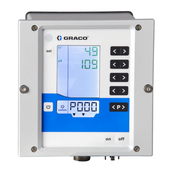
Page 38: Controller Display And Features
Controller Display and Features Controller Display and Features SAFE POSITION Interlock Screen Areas satisfied 24 VDC Interlock satisfied There are five areas on the screen used for Electrostatic Enable input is numerical information. Six additional areas provide Active non-numerical information. Icons Icon Explanation... -
Page 39: Input Keys And Switches
Controller Display and Features Input Keys and Switches Additional Features NOTICE Keyboard Lock To prevent damage to the softkey buttons, The keyboard lock can be used to prevent changes do not press the buttons with sharp objects to individual voltage and current parameter values such as pens, plastic cards, or fingernails. - Page 40 Controller Display and Features Checking the Software Version 1. Press off on the controller. 2. Press and hold 1. Press the key and the at the same time. 3. Press on on the controller. The CLr display blinks. 4. Wait for approximately 5 seconds, until CLr 2.
-
Page 41: Setup
Setup Setup The Electrostatic Controller has setup screens that NOTE: Press to access Setup Screens 8–11 define how the controller functions. This setup is (Configuration). Press buttons T1/T2 to move saved in the equipment memory, even when power is between Screens 8–11. To return to Setup removed. - Page 42 Setup PARAMETERS Setup Display Description Display (A3) Values Display Screen (A1) (A4) Value Value CAN Purpose ID 0–32 0 (default) Use to set the purpose ID for CAN communication. Log level 0–5 Display A2: LoG 2 (default) Use to designate how much information is logged in the system.
-
Page 43: Setup Screen 0 (System Type)
Setup Setup Screen 0 (System Type) Setup Screen 1 (Electrostatics Control Mode) Setup Screen 0 (Parameter P00) displays the type of electrostatic applicator (APP) in use. The Setup Screen 1 (Parameter P01) displays the Electrostatic Controller is factory set to 0 (Std) or 1 electrostatics control mode (Ctrl) in use. -
Page 44: Setup Screen 2 (Remote Interface)
Discrete I/O, page for more information. • 2 = CAn: CAN interface is enabled. The CAN interface is used to communicate with Graco modules. When CAN interface is enabled, all inputs except Electrostatic Enable are disabled. All outputs function normally. [See Discrete I/O, page 20.]... -
Page 45: Setup Screen
Setup Setup Screen 3 (Analog Input Type Setup Screen 4 (Analog Output Type Select) Select) Use Setup Screen 3 (Parameter P03) to select the Use Setup Screen 4 (Parameter P04) to select the input signal type for the discrete I/O interface analog output signal type for the discrete I/O interface analog inputs (Ai). -
Page 46: Setup Screen
Setup Setup Screen 5 (Digital Output Type Setup Screen 6 (CAN Purpose ID) Select) Use Setup Scree 6 (Parameter P06) to select the CAN purpose ID of the controller. For systems with Use Setup Screen 5 (Parameter P05) to select the one applicator, set the value to 0 (default). -
Page 47: Setup Screen 7 (Log Level)
Setup Setup Screen 7 (Log Level) Setup Screen 8 (Averaging Interval) Use Setup Screen 7 (Parameter P07) to select the Use Setup Screen 8 (Configuration C0) to select the log level (LoG) for how much information is logged in averaging interval (in seconds) used to calculate the the system (used for troubleshooting only). -
Page 48: Setup Screen 9 (Blanking Time)
Setup Setup Screen 9 (Blanking Time) Setup Screen 10 (Discharge Timer) The Electrostatic Controller uses a fixed blanking Use Setup Screen 10 (Configuration C2) to select time which is defined by this screen. The blanking the time (in seconds) from when the electrostatics time is the time between when electrostatics are are disabled until the electrostatics discharged output activated and Arc Detection is enabled. -
Page 49: Setup Screen 11 (Transition Time)
Setup Setup Screen 11 (Transition Time) • Default is 0.0 (shown) The transition time is the time over which the controller changes the electrostatics. The transition time applies when electrostatics are enabled and when the Voltage Setpoint is changed. Arc detection remains active when the voltage setpoint is changed. -
Page 50: Operation
Operation Operation System Start-up Presets Press on to turn on the controller. The controller The Electrostatic Controller has 251 (P000-P250) always starts up to the last configured settings. user-defined Presets. There are four values The controller has two sets of screens, Run and associated with each Preset. -
Page 51: Run Screen 1 (Electrostatic Readings)
Operation Run Screen 1 (Electrostatic Readings) Press to select the Preset (P000 — P250). Press to acknowledge error codes. To reduce the risk of electric shock, do not use the Electrostatic Controller readings to determine if your system is discharged. The controller will only display the voltage while the applicator’s power supply is operating. -
Page 52: Run Screen 2 (Arc Limits)
Operation Run Screen 2 (Arc Limits) Run Screen 2 is the secondary screen for the NOTE: It is recommended that arc detection settings electrostatic applicator. This screen shows the active not be changed from defaults. Any desired change Preset, arc detection limits, and screen backlight must be set individually for every Preset. -
Page 53: Run Screen 3 (Maintenance Counters)
Operation Run Screen 3 (Maintenance Counters) Run Screen 3 is the maintenance screen. This number. The service symbol also will appear. screen shows the 4 maintenance counters and the Controller operations are not stopped. non-resettable trigger counter. NOTE: Maintenance counters, states When dashes are shown in the maintenance (active/inactive), and set points are not reset counters, monitoring is deactivated. -
Page 54: Arc Detection
Operation Arc Detection also may supply a grounded plate that meets the requirements specified in the illustration. The test must be conducted with no fluid in the applicator and The primary method to prevent arcing to the the shaping airs off. workpiece is to keep the charged components of the applicator at least 6 in. - Page 55 Operation Arc Detection Adjustments The following parameters can be changed to influence the arc detection performance. Remarks Setting Static Arc Limit * Range: 0.1–2 nS Set the value lower to increase sensitivity and to deactivate the electrostatics sooner as a grounded object approaches the applicator. Set View or change on Run Screen the value higher to decrease sensitivity and to eliminate nuisance errors.
- Page 56 Operation Live Arc Detection Values arc detection error should not occur, but creates an error anyway.) Set your static and dynamic arc detection limits above the largest numbers seen on Press and hold the SEL button from Run Screen 1. the screen.
-
Page 57: Screen Map
Screen Map Screen Map SETUP SCREENS 0–7 SETUP SCREENS 8–11 (Parameters) (Configurations) Press and hold for 5 seconds Press and hold for 5 seconds Press from SETUP SCREENS from any SETUP screen. Also from any RUN screen. Or, press 0–7. shown on power up. - Page 58 Screen Map SETUP SCREENS 0–7 SETUP SCREENS 8–11 (Parameters) (Configurations) T1/T2 T1/T2 T1/T2 T1/T2 T1/T2 T1/T2 3A3657C...
- Page 59 Screen Map SETUP SCREENS 0–7 SETUP SCREENS 8–11 (Parameters) (Configurations) T1/T2 T1/T2 T1/T2 3A3657C...
- Page 60 Screen Map SETUP SCREENS 0–7 SETUP SCREENS 8–11 (Parameters) (Configurations) T1/T2 3A3657C...
-
Page 61: Troubleshooting
Troubleshooting Troubleshooting Error Codes The Electrostatic Controller is monitored constantly. If a error is detected, an error message is indicated with a error code. The error codes are shown in red on the A5 display. The four most recent error codes are stored by the order of their appearance. Each error in the list must be acknowledged with the key. - Page 62 Troubleshooting Code Description Criteria Controller Solution Action Arc detection A grounded object came too Stop • Verify closest distances to parts. both limits close to the applicator at too • Verify fastest approach to parts. high of a speed. Arc detection Arc detection triggered due to Stop •...
- Page 63 • Verify that the power supply is meant type detected connected to the controller to be used with this controller. Graco CAN Bus Errors CAN Bus Off The CAN controller went to bus Stop • Verify that parameter P02 on Setup...
-
Page 64: Power Cable Continuity
Troubleshooting Code Description Criteria Controller Solution Action Other Errors These will be logged, but not likely to be seen on the display due to restart H901 Restart Assertion failed Violation of a mandatory precondition • Verify that all connections inside of H902 Out of memory Memory allocation failed... -
Page 65: Repair
Repair Repair Individual items used in this controller are not 3. Remove connectors from the main board and repairable. If they fail, they must be replaced. See from the power supply, as shown. Parts, page 69, for a list of repair kits. NOTICE To avoid damaging the circuit boards when servicing the control box, wear Part No. - Page 66 Repair 4. Using a 5.5 mm (7/32” socket) tool, remove four 8. Remove 2 screws and lift out the membrane nuts from the main board. Disconnect the three (button) panel. remaining cables. 5. Lift the main board carefully out of the module. 6.
-
Page 67: Power Supply Board Removal
Repair Power Supply Board Removal 3. Remove the two electrical connectors from the power board, as shown. 1. Remove power from the system. 2. Remove four screws, then remove the back access panel. 4. Gently pry the power board from the four retaining clips and remove the board, as shown. -
Page 68: Software Update
Repair Software Update 6. Apply power to the Electrostatic Controller and press the on button. The screen should blink and display donE when the reprogramming is complete. NOTE: Prior to beginning a software update, make a written copy of Preset settings that have been defined for use with the specific materials being applied with this system. -
Page 69: Parts
The software does not affect the portion of 17H286 Power Board controller memory that defines the type of system. 17H285 Power Supply Board 17H283 Button Panel Graco CAN Cables 17H282 LCD Panel 25C427 CAN Board Part No. Description 130193 0.5 m (1.6 ft) 121001 1 m (3.3 ft) -
Page 70: Dimensions
Dimensions Dimensions Controller 3A3657C... - Page 71 Dimensions Flush Mount 5.71 in. (15.0 cm) 3.30 in. (8.4 cm) 7.65 in. (19.4 cm) M6 X 1 mm 6.26 in. (15.9 cm) Wall Mount Bracket 17H288 3A3657C...
-
Page 72: Notes
Notes Notes 3A3657C... -
Page 73: Technical Specifications
Technical Specifications Technical Specifications ProBell Electrostatic Controller U.S. Metric Nominal Input Voltage 100–240 VAC Frequency 50–60 Hz Input Power 40 VA Nominal Output Voltage (to the eff 10V applicator) Nominal Output Current (to the max 1.2 A applicator) External Power Requirements... -
Page 74: Graco Standard Warranty
Graco to be defective. This warranty applies only when the equipment is installed, operated and maintained in accordance with Graco’s written recommendations. This warranty does not cover, and Graco shall not be liable for general wear and tear, or any malfunction, damage or wear caused by faulty installation, misapplication, abrasion, corrosion, inadequate or improper maintenance, negligence, accident, tampering, or substitution of non-Graco component parts.
Need help?
Do you have a question about the ProBell Electrostatic Controller and is the answer not in the manual?
Questions and answers