Graco PrecisionFlo XL Instructions Manual
Hide thumbs
Also See for PrecisionFlo XL:
- Manual (34 pages) ,
- Instructions-parts list manual (20 pages)
Table of Contents
Advertisement
Quick Links
Parts
Instructions
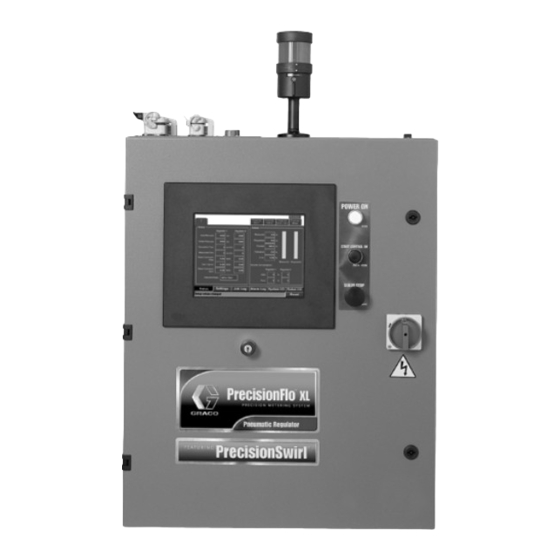
PrecisionFlo XL
Electronically controlled fluid dispensing packages
S Pneumatically or electrically operated fluid regulators
S EasyKey
Maximum Working Pressures of packages ordered through the PrecisionFlo XL configurator:
GRACO INC. P.O. BOX 1441 MINNEAPOLIS, MN 55440-1441
Copyright 2001, Graco Inc. is registered to I.S. EN ISO 9001
R
Keypad or TouchScreen interface.
Maximum Fluid Feed Pressure
5000 psi (34.5 MPs, 345 bar) Ambient and Temperature Conditioned
3000 psi (20.7 MPa, 207 bar) Electrically Heated (hoses)
Maximum Working Air Pressure
120 psi (.83 MPs, 8.3 bar) All Pneumatic Components
Read warnings and instructions.
Certified to
CAN/CSA C22.2
Conforms to
UL 3121–1
309374E
Advertisement
Table of Contents
Troubleshooting

Related Manuals for Graco PrecisionFlo XL


Summary of Contents for Graco PrecisionFlo XL
- Page 1 S Pneumatically or electrically operated fluid regulators S EasyKey Keypad or TouchScreen interface. Maximum Working Pressures of packages ordered through the PrecisionFlo XL configurator: Maximum Fluid Feed Pressure 5000 psi (34.5 MPs, 345 bar) Ambient and Temperature Conditioned 3000 psi (20.7 MPa, 207 bar) Electrically Heated (hoses) Maximum Working Air Pressure 120 psi (.83 MPs, 8.3 bar) All Pneumatic Components...
-
Page 2: Table Of Contents
........PrecisionFLo XL Remote Control Box . -
Page 3: Symbols
Warnings Warnings Warning Symbol Caution Symbol WARNING CAUTION This symbol alerts you to the possibility of serious This symbol alerts you to the possibility of damage to injury or death if you do not follow the instructions. or destruction of equipment if you do not follow the instructions. - Page 4 D Comply with all applicable local, state and national fire, electrical and other safety regulations. D Do not touch the metal heat sink on the metering valve when the surface is hot. D Do not cover the PrecisionFlo XL linear metering valve; the motor needs air ventilation for cooling.
- Page 5 D Make sure all electrical equipment is installed and operated in compliance with applicable codes. D Do not install the PrecisionFlo XL module in a hazardous area, as defined in Article 500 of the National Electrical Code (USA). D Turn off power to the PrecisionFlo XL module before disconnecting any cables connected to the control unit or other components.
-
Page 6: Model Identification
Model Identification PrecisionFlo XL Model Number Identification Graco’s PrecisionFlo XL is an electronically controlled On your control unit, there is an ID plate with a model fluid regulating package designed to meter and dis- number on it. Use the table on page 7 for explana- pense adhesives and sealants. - Page 7 Accy. – Listed in Accessories section of manual. XL–E PrecisionFlo Fluid Module Dual Pneumatic Regulators (2 Fluid Plates) Code A Configuration Low Viscosity (1/2” reg) 308647 PrecisionFlo XL Package 309374 Med/High Viscosity (3/4” reg) 307517 Electrical Enclosure Only 309374 Code J Flow Meter Code B Enclosure None –...
-
Page 8: Overview
What This Manual Includes PrecisionFlo XL Definitions Refer to pages 9–11. This manual provides detailed information on the PrecisionFlo XL control unit and operation of the PrecisionFlo XL system only. Specific information on Component Description the fluid module or material conditioning systems, for... -
Page 9: Typical Precisionflo Xl Configuration
Typical PrecisionFlo XL Configuration Typical PrecisionFlo XL Configuration Fig. 1 shows the major components in a typical PrecisionFlo XL installation. Fig. 1 Description Control Unit Fluid Module Applicator/Dispense Gun User Interface Sealer Robot Robot Digital Interface Cable (RDR) Fluid Supply System... -
Page 10: Sound Deadener Package
Typical PrecisionFlo XL Configuration Sound Deadener Package with Dual Flow Meters and Swirl Orbiters 309374... -
Page 11: Pneumatic Regulator Package
Typical PrecisionFlo XL Configuration Pneumatic Regulator Package for Extrusion or Streaming Operation Cable 309374... -
Page 12: Installation
Installation Installation Overview The basic steps to install a Graco PrecisionFlo XL system are shown below. See the separate component manuals listed for detailed information. Installation Steps Manual 1. Mount XL control unit 309374, pg. 13 2. Ground XL control unit. -
Page 13: Mounting Control Unit
Installation 1. Select a location for the PrecisionFlo XL control Mounting Control Unit unit that allows adequate space for installation, service, and use of the equipment. See Fig. 2. If you are using the remote display and the Precision-Flo XL control unit witll be mounted... - Page 14 Installation Temperature Control Packages See page 136 for additional information on the optional Temperature Control Package. Temperature-Conditioned Package 12.8” 24.5” 325 mm 622 mm Heat Only 26” 660 mm 24” 610 mm Heat/Cool 36” 914 mm 60.5” 1.54 m 72” 1.83 m TI1484A Fig.
-
Page 15: Electrical Connections
Connect a ground wire from the ground point in the PrecisionFlo XL control enclosure to a true earth WARNING ground. See Fig. 5. A 10 AWG, 25 ft. (7.6 m) long ground wire with clamp, Part No. 222011, is supplied. -
Page 16: Connecting Cables
Route cables carefully. Avoid pinching and premature used. Refer to PrecisionFlo XL I/O Interface on page wear due to excessive flexing or rubbing. Cable life is 89 and also on form 309364 for schematics. -
Page 17: Checking Ground Continuity
Swirl Cable Connector (optional) Motor Power Cable — This cable supplies power to Checking Ground the linear motor (when used) from the PrecisionFlo XL. The motor requires a higher DC voltage signal that Continuity cannot be combined with signals in the Operations Cable. -
Page 18: Connecting Fluid And Air Lines
– Connect the meter signal to the fluid module. D The PrecisionFlo XL fluid module should be D Connect an air supply line to the 1/4 npt inlet port installed on the robot or in another appropriate place, as close as practical to the dispense valve. -
Page 19: Connecting To Power Source
WARNING Full Load 25.1 12.6 ELECTRIC SHOCK HAZARD Amps. Do not connect the PrecisionFlo XL con- trol unit to a power source unless you With Temperature Conditioning are a trained electrician. Option G–2 (50 Hz) Heat Only VAC: 200 – 240 400 –... -
Page 20: Pressure Relief Procedure
Air Solenoid To Dispense Valve WARNING The PrecisionFlo XL module pressure must be manually relieved to prevent the module from starting or spraying acciden- tally. To reduce the risk of serious injury, including fluid injection, splashing in the eyes or on... -
Page 21: Precisionflo Xl User Interface
Key Groups Action Keys D Dispense Gun 1 — is used for functions related to There are three groups of keys on the PrecisionFlo XL the primary regulator and dispense gun, including user interface. Manual Dispense, Autotune, and Flow Calibration. - Page 22 Operation TouchScreen User Interface Overview Fig. 10 The TouchScreen interface allows you to make selec- A keypad appears when you touch a data field that tions by touching the screen. Use your index finger to requires you enter numerical information. move the TouchScreen cursor to any location on the screen.
-
Page 23: Starting The System
Operation 3. Turn on the main electrical disconnect (2) to supply Initial Startup power to the PrecisionFlo XL module. See Fig. 12. The user interface becomes active, showing first a Read and understand Operation diagnostic message and then the first screen. The section of this manual Power On indicator light (3) turns on. -
Page 24: Control Unit Buttons, Switches And Indicators
Ground Connected Power is off. light Control On light PCR is engaged and the PrecisionFlo XL Control Assembly is ready for operation. PrecisionFlo XL control assembly is not ready for operation. User Display Display is on when power is applied to the control assembly. -
Page 25: Loading Material
Master Start button (1, Fig. 12) to turn on power to the PrecisionFlo XL fluid module(s). The PrecisionFlo XL system has two operating modes: On the keypad, perform the following steps: D Automatic dispense mode — enables the 1. - Page 26 Master Start button (1, Fig. 12) to turn on 3. To start dispensing from Gun 1, touch and hold power to the PrecisionFlo XL fluid module(s). Dispense Gun 1 button. Dispensing continues as long as you continue to touch Dispense Gun 1.
-
Page 27: Robot Modes
3. To change the mode, press the down arrow key B Robot Modes until the cursor is over the mode cell. The PrecisionFlo XL system has two robot modes: 4. Press Enter and use the up and down arrow keys, Y or B, to change values. -
Page 28: Control Modes
2. The control mode is indicated on this screen, Control Modes either Pressure or Flow. The PrecisionFlo XL module has two fluid dispensing 3. To change the mode, press the down arrow key B control modes: until the cursor is over the mode cell. -
Page 29: Shutting Down The System
To reduce the risk of serious injury whenever you are instructed to relieve pressure, always follow the Pressure Relief Procedure on page 20. 3. Turn off the PrecisionFlo XL system’s compressed air supply. 4. Press the Sealer Stop button (7). See Fig. 13. -
Page 30: Configuring Software
PrecisionFlo XL software. Configure Software To configure the PrecisionFlo XL software, perform the following procedure. When you have completed this procedure, the module is ready for operation. Calibrate pressure 1. -
Page 31: Setting Flow Meter K-Factors
Setting Flow Meter TouchScreen Interface K–Factors Set Flow Meter K-Factor The accuracy of the PrecisionFlo XL volume reporting On the TouchScreen, perform the following steps: depends on precise adjustment of the K-factor(s). The control unit uses the K-factor(s) to calculate the vol- 1. -
Page 32: Calibrating Pressure
Configuring Software Calibrating Pressure EasyKey Interface The PrecisionFlo XL system uses variables (Kp and Calibrate Pressure Ki) in the software calculations to accurately and On the keypad, perform the following steps: precisely control the fluid pressure and flow rate. The 1. -
Page 33: Flow Rate Calibration
Configuring Software Table 5—Maximum Flow Rate Values (cc/min) Flow Rate Calibration You only calibrate flow rate if you are operating in Round Equivalent Bead Diameter (mm) Flow Mode. If your system does not have a flow Max. Robot meter or you are operating in Pressure Mode, you do Speed (mm/sec) not calibrate the flow rate. -
Page 34: Other Software Settings
Configuring Software Calibrating Flow Rate TouchScreen Interface Before Calibrating 1. Verify that the system is in setup mode. Calibrate Flow 2. Verify that dispense device(s) are placed over a On the TouchScreen, perform the following steps: material waste container. 1. Touch Calibration and Flow buttons. 3. - Page 35 There are additional variables that should be set after the path programming is completed, they include; High/Low pressure settings and Style (volume) information. Table 6—PrecisionFlo XL User Variables and Presets Values in italics are factory defaults. Screen Variable / Preset...
- Page 36 Configuring Software Other System Variables After the calibration and robot path programming is complete and the desired bead profiles have been achieved, verify that the following variables are set. Table 7—PrecisionFlo XL System Variables Screen Variable / Preset Values Comments Setup2 –...
-
Page 37: On/Off Delays
High trapped pressures The PrecisionFlo XL regulator (or metering valve) can shorten the dispense device life. physically respond faster than the dispense device and its solenoid. -
Page 38: Verifying Flow Meter Calibration
Verifying Flow Meter Calibration Verifying Flow Meter Calibration Verification and Calibration 5. Calculate the new flow meter K-factor: displayed volume (cc) x K–Factor (old) K–Factor (new) = measured volume (cc) Most sealant and adhesive materials are compressible. Since the flow meter is measuring the material under high pressure, the actual volume of material dispensed 6. -
Page 39: Communicating With Precisionflo Xl
Data Transfer c. Restore settings to factory defaults activate the Graco Shell by pressing the Enter key on Enter Selection [a–c]: the keyboard. The main menu will be displayed. Welcome to the Graco Control Application Menu If option “b”... -
Page 40: Precisionflo Xl Module Operation
Select option “e”. The main menu will be shown. 1. Go to the Transfer –> Receive... menu Welcome to the Graco Control Application Menu 2. Select the Y–Modem protocol Build date: Jul 06 2001 15:45:38 (debug build) 3. Specify the directory to store the setup a. -
Page 41: Precisionflo Xl Easykey Interface
PrecisionFlo XL EasyKey Interface PrecisionFlo XL EasyKey Interface EasyKey Keypad Overview EasyKey Number Keys Dispense Gun 1 Enter Key Dispense Gun 2 Fault Reset Screen Navigation Keys Auto/Manual Data Field Navigation Keys Fig. 17 D Dispense Gun 2—Used for functions related to the... - Page 42 PrecisionFlo XL EasyKey Interface Screen Overview Overview Screen The purpose of this screen is to display an overview of the process parameters. The Reg 2 column will only be shown for dual regulator systems. 21:45 Jan–04–2001 REG 1 REG 2...
- Page 43 PrecisionFlo XL EasyKey Interface Job Data Screen The purpose of this screen is to display job information for the last job completed. Style: XXXXXXXXX Comp. Reg 1: Zero XXXX% Peak XXXX% Comp. Reg 2: Zero XXXX% Peak XXXX% Volume: Zone Temp Measured XXX.X cc...
- Page 44 PrecisionFlo XL EasyKey Interface Job Log Screen The purpose of this screen is to display a summary of the most recent jobs. The most recent eight jobs are initially displayed on the screen. Pressing the down arrow, B, on the keypad brings up the previous eight jobs. The up arrow on the keypad, Y, scrolls back first eight.
- Page 45 PrecisionFlo XL EasyKey Interface Alarm Log Screen The purpose of this screen is to display a summary of the most recent alarms. The most recent eight alarms are initially displayed on the screen. Pressing the down arrow, B, on the keypad brings up the previous eight alarms.
- Page 46 PrecisionFlo XL EasyKey Interface Setup 1—Modes Screen Robot Mode: Digital Control Mode: Pressure Swirl Mode: Manual Robot Interface: Discrete Flow Scale Reg #1 XXX% Swirl Auto XXX% Flow Scale Reg #2 XXX% Swirl Manual XXX% Modes Dispense Config Setup 1...
- Page 47 PrecisionFlo XL EasyKey Interface Setup 1—Dispense Screen The purpose of this screen is to set parameters related to the dispense cycle. Reg 1 Reg 2 Flow Meter K-Factor XXXXX XXXXX /L * Flow Average pulses Pressure Mode psi/v Gun on Delay...
- Page 48 PrecisionFlo XL EasyKey Interface Setup 1—Configuration Screen The purpose of this screen is to allow users to configure a number of general parameters. Job End Mode Robot I/O Language English Pressure Units Temp. Control None Number of Regulators Number of Swirls...
- Page 49 PrecisionFlo XL EasyKey Interface Setup 2—Setup Screen The purpose of this screen is to allow users to set up style parameters. When this screen is selected, the first volume field will be highlighted. When the user tabs past the last tolerance field, the next eight styles will be dis- played and the first volume field will be highlighted.
- Page 50 PrecisionFlo XL EasyKey Interface Setup 2—Values Screen Low Flow Rate XXX% Medium Flow Rate XXX% High Flow Rate XXX% Manual Gun Flow Rate XXX% Job End Delay Time XXX sec Styles Set Clock Temp Cont Values Setup 1 Setup 2...
- Page 51 PrecisionFlo XL EasyKey Interface Setup 2—Set Clock Screen The purpose of this screen is to set parameters for time and date. The date is entered in MM–DD–YYYY format. Time is entered in HH:MM format. 21:45 Jan-04-2001 Year XXXX Month Hour...
- Page 52 PrecisionFlo XL EasyKey Interface Setup 2—Temperature Control Screen Zone On/Off Autotune Fld Plate Disp Vlv Set Point High Lim Low Lim Temp Units: Celsius Styles Set Clock Temp Cont Values Setup 1 Setup 2 Calibration Faults No Active Alarms Fig. 27 Table 17—Temperature Control Screen Values...
- Page 53 PrecisionFlo XL EasyKey Interface Calibration—Pressure Screen Dispense Mode: Manual Reg 1 Reg 2 Inlet Voltage at 0 psi X.XX X.XX Outlet Voltage at 0 psi X.XX X.XX Inlet Press at 5 V XXXX XXXX Outlet Press at 5 V XXXX...
- Page 54 PrecisionFlo XL EasyKey Interface Calibration—Flow Rate Screen Dispense Mode: Manual Reg 1 Reg 2 Max Robot Speed mm/sec Bead Diameter XX.X XXX. Max Flow Limit XXXX XXXX cc/mm * Flow Cal Pressure XXXX XXXX Outlet Press XXXX XXXX Flow Rate...
- Page 55 PrecisionFlo XL EasyKey Interface Faults—Action Screen The purpose of this screen is to set the alarms to be either warnings or alarms. An alarm will stop the system, but a warning will not. When this screen is selected, the top fault field is highlighted. The fault warning/alarm status can then be toggled by pressing the Enter key.
- Page 56 PrecisionFlo XL EasyKey Interface Faults—Parameters Screen # Jobs with High Volume to Fault # Jobs with Low Volume to Fault Time with No Flow to Fault XXX sec Pressure Limits Inlet Lo Inlet Hi Outlet Lo Outlet Hi Reg 1...
-
Page 57: Precisionflo Xl Touchscreen Interface
PrecisionFlo XL TouchScreen Interface PrecisionFlo XL TouchScreen Interface Setup Mode– Navigation Bar and Fault Status Bar Fig. 32 Run Mode– Navigation Bar and Fault Status Bar Fig. 33 Numeric Pop-Up Keypad Fig. 34 Alpha-Numeric Pop-Up Keypad 16-character limit 309374... - Page 58 PrecisionFlo XL TouchScreen Interface Setup Screens Setup – Modes Screen Fig. 36 Table 21—Setup Modes Screen Values Description Possible Values Operational Modes Robot Mode Analog/Digital Control Mode Pressure/Flow Swirl Mode Automatic/Manual Robot Interface Serial/Discrete Global Adjustments Flow Scale Reg #1 50–150...
- Page 59 PrecisionFlo XL TouchScreen Interface Setup – Dispense Screen Fig. 37 Table 22—Setup Dispense Screen Values Description Possible Values Default Value Flow Meter K Factor (pulses/Lt) 0-99,999 Set at factory for specific system Flow Average (pulses) 0-99 Sets automatically at flow calibration...
- Page 60 PrecisionFlo XL TouchScreen Interface Setup – Styles Screen Fig. 38 Table 23—Setup Styles Screen Values Description Possible Values Style Bit & Name Enter style names using pop-up alphanumeric keypad Volume (cc) 0-99,999 Tolerance (%) 0-99.9 309374...
- Page 61 PrecisionFlo XL TouchScreen Interface Setup – Values Screen Fig. 39 Table 24—Setup Values Screen Values Description Possible Values Default Value *Low Speed Bit (Default) (%) 0-100% Medium Speed Bit (%) 0-100% High Speed Bit (%) 0-100% Manual Gun (%) 0-100%...
- Page 62 PrecisionFlo XL TouchScreen Interface Setup – Trend Screen Fig. 40 Table 25—Setup Trend Screen Values Description Possible Values Signals (Select signals to display) Inlet Pressure Regulator 1/Regulator 2 Outlet Pressure Regulator 1/Regulator 2 Desired Pressure Regulator 1/Regulator 2 Requested Flow Regulator 1/Regulator 2...
- Page 63 PrecisionFlo XL TouchScreen Interface Setup – SPC Screen Fig. 41 Table 26—Setup SPC Screen Values Description Possible Values Style As entered on Setup Styles screen (Fig. 38) Number of jobs 1-65,000 Tolerance Reads the tolerance value set for the corresponding style name on the Setup Styles screen.
- Page 64 PrecisionFlo XL TouchScreen Interface Config – General Screen (1 regulator) Fig. 42 Config – General Screen (2 regulators) Fig. 43 309374...
- Page 65 PrecisionFlo XL TouchScreen Interface Table 27—Config General Screen Values (1 regulator) Description Possible Values Default Job End Mode Robot I/O/Timer Timer Language English/French/German/Italian/ English Japanese/Korean/Portugese/ Spanish Pressure Units bar/PSI Temperature Control None/Electric Heat/Temperature None Conditioning Number of Regulators One/Two Number of Swirls...
- Page 66 PrecisionFlo XL TouchScreen Interface Config – Temperature Screen Fig. 44 Table 28—Config Temperature Screen Values Description Possible Values Zones 1 – 4 On/Off PID—Close Window Autotune/Dispense Valve/Fluid Plate/Hose/Regulator/ *The PID field will display “Autotune” if there is an Auto- Done tune in progress.
- Page 67 PrecisionFlo XL TouchScreen Interface Config – Set Clock Screen Fig. 45 Table 29—Config Set Clock Screen Values Description Possible Values Time Zone Eastern/Central/Mountain/Pacific/Alaska/Hawaii/Samoa Year 2000–2038 Month 1–12 1–31 Hour 1–24 Minute 0–23 Second 0–59 309374...
- Page 68 PrecisionFlo XL TouchScreen Interface Config – IP Configuration Screen Fig. 46 See Appendix A: Ethernet and FTP for an explanation of how to use this screen. 309374...
- Page 69 PrecisionFlo XL TouchScreen Interface Config – Backup Screen Fig. 47 Table 30—Config Backup Screen Values Description Possible Values Load Any previously saved setup file Save As Enter file name using pop-up alpha-numeric keypad Load Factory Defaults Reloads the factory set parameters Use this screen to save your current setup parameters to a retrievable file on the hard drive of your PC or to re- trieve a previously saved setup file.
- Page 70 PrecisionFlo XL TouchScreen Interface Logs – Job Log Screen Fig. 48 Table 31—Logs Job Log Screen Values Description Job Number Date Time Style Volume Meas. Req. Process % Error 309374...
- Page 71 PrecisionFlo XL TouchScreen Interface Logs – Alarm Log Screen Fig. 49 Table 32—Logs Alarm Log Screen Values Description Fault Number Date Time Fault Code Description Status Reset Fault # 309374...
- Page 72 PrecisionFlo XL TouchScreen Interface Calibration – Pressure Screen Fig. 50 Table 33—Calibration Pressure Screen Values Description Possible Values *Inlet Voltage at 0 Pressure 0.0–2.0 V *Outlet Voltage at 0 Pressure 0.0–2.0 V [Inlet Pressure at 5 V 0.0–344.83 bar/0.0–5000 PSI [Outlet Pressure at 5 V 0.0–344.83 bar/0.0–5000 PSI...
- Page 73 PrecisionFlo XL TouchScreen Interface Calibration – Flow Screen Fig. 51 Table 34—Calibration Flow Screen Values Description Possible Values Maximum Robot Speed 0.0–999.0 mm/s Bead Diameter 0.0–99.9 mm Maximum Flow Limit 0.0–5000.0 cc/min Flow Calibration Pressure Actual Outlet Pressure Actual Actual Flow Rate...
- Page 74 PrecisionFlo XL TouchScreen Interface Faults – Level 1 Screen Fig. 52 Table 35—Faults Level 1 Screen Values Description Possible Values Default Value 1. Dispenser stop Always Alarm Alarm 2. Drive Fault 1 Always Alarm Alarm 3. Spare None 4. Motor Over Temp 1...
- Page 75 PrecisionFlo XL TouchScreen Interface Faults – Level 2 Screen Fig. 53 Table 36—Faults Level 2 Screen Values Description Possible Values Default Value 17. High Inlet Pressure 2 Alarm/Warning Warning 18. Low Inlet Pressure 1 Alarm/Warning Warning 19. Low Inlet Pressure 2...
- Page 76 PrecisionFlo XL TouchScreen Interface Faults – Parameters Screen Fig. 54 Table 37—Faults Parameters Screen Values Description Possible Values Volume Fault Buffering Number of Jobs with High 0–999 Volume to Fault Number of Jobs with Low 0–999 Volume to Fault Time with No Flow to Fault 1–999...
- Page 77 PrecisionFlo XL TouchScreen Interface Help – About Screen Fig. 55 309374...
- Page 78 PrecisionFlo XL TouchScreen Interface Run Screens Status Screen (1 regulator) Fig. 56 Status Screen (2 regulators) Fig. 57 309374...
- Page 79 PrecisionFlo XL TouchScreen Interface Table 38—Status Screen Values Description Possible Values Status Inlet Pressure Reg 1 and 2 0–9999 psi Outlet Pressure Reg 1 and 2 0–9999 psi Requested Flow Reg 1 and 2 0–9999 cc/min Measured Flow Reg 1 and 2 0–9999 cc/min...
- Page 80 PrecisionFlo XL TouchScreen Interface Settings Screen Fig. 58 Table 39—Settings Screen Values Description Possible Values Default Value Mode Robot Mode Analog/Digital Digital Control Mode Pressure/Flow Pressure Swirl Mode Manual/Automatic Manual Robot Interface Discrete/Serial Serial Totalizer Resettable Total Grand Total Scale...
- Page 81 PrecisionFlo XL TouchScreen Interface Job Log Screen Fig. 59 309374...
- Page 82 PrecisionFlo XL TouchScreen Interface Alarm Log Screen Fig. 60 309374...
- Page 83 PrecisionFlo XL TouchScreen Interface System I/O – Input Screen Fig. 61 System I/O – Output Screen Fig. 62 309374...
- Page 84 PrecisionFlo XL TouchScreen Interface Robot I/O – Input Screen Fig. 63 Robot I/O – Output Screen Fig. 64 309374...
- Page 85 PrecisionFlo XL TouchScreen Interface Notes 309374...
-
Page 86: Precisionflo Xl Remote Screen Interface
12 characters with no spaces. Be sure to will be using. enter these numbers correctly so the remote Touch- Screen can communicate with the PrecisionFlo XL. When your system is configured with a remote Touch- Screen, the screen shown in Fig.66 appears when you enter setup mode (key switch clockwise). - Page 87 PrecisionFlo XL Remote Screen Interface Go to Station 1 Physical Address Field (Station 1) NOTE: The numbers shown on this sample screen are for refer- ence only. You will en- ter the actual address- es found on the Ether- net chip on the local stations.
- Page 88 When operating with a remote TouchScreen, the run screens are the same as with an integrated Touch- When the PrecisionFlo XL key switch is turned to run Screen except that a small icon at the top of each mode, the screen shown in Fig. 68 appears. Touch the screen indicates which local station you are controlling.
-
Page 89: Robot I/O Interface
Robot I/O Interface Robot I/O Interface Table 40—Robot Interface Analog Inputs to the PrecisionFlo XL Refer to page 98 for more information on analog signals. Signal Name Wire Board ID Cable Signal Description Analog Flow Command 1 3280 J1–21 RAR–1 Robot speed command for Fluid Control plate 1. - Page 90 RDR–A13 Style bit #16 Low Speed 8680 J5–14 RDR–A14 When this signal is HIGH and digital robot mode is selected, the PrecisionFlo XL will default to a preset Low Speed setting in the controller. Med Speed 8690 J5–15 RDR–A15 When this signal is HIGH and digital robot mode is selected, the PrecisionFlo XL will default to a preset Medium Speed setting in the controller.
- Page 91 Robot I/O Interface Table 42—Robot Interface Digital Outputs from the PrecisionFlo XL See page 98 for more information on digital outputs. Signal Name Wire Board ID Cable Signal Description 2190 J1–1 RDR–B9 Interface power (24 VDC or 120 VAC, depending on board).
- Page 92 Robot I/O Interface Table 43—Fault Codes Bit Description Fault Fault Description Level Code Dispenser Stop MCR/PCR is not energized Alarm Drive Fault 1 Linear motor amplifier board fault Alarm Spare Spare – Motor Over Temp 1 Linear motor above 90 degrees C or sensor open Alarm Spare Spare...
- Page 93 Robot I/O Interface Table 43—Fault Codes Bit Description Fault Fault Description Level Code Volume Comp Limit 1 Regulator 1 peak volume compensation reached 25% Alarm or Warning or 400% limit Volume Comp Limit 2 Regulator 2 peak volume compensation reached 25% Alarm or Warning or 400% limit Computed Target...
-
Page 94: Discrete Signals
Robot I/O Interface Discrete Signals Robot I/O Board shown (inside PrecisionFlo XL control unit) Fig. 70 Note: The transparent circuit board cover over the discrete I/O board in the control box, identifies the location of the LEDs. 309374... - Page 95 Robot I/O Interface Table 44—Anybus I/O to the PrecisionFlo XL (16 bytes of data from Cell Controller to PrecisionFlo XL) For more information regarding the device networks, visit the website www.anybus.com. Node PrecisionFlo XL GM–RS4 Spec Comments Address Variable Byte 1...
- Page 96 Robot I/O Interface Table 45—PrecisionFlo XL I/O to Cell Controller Node PrecisionFlo XL GM–RS4 Spec Comments Address Variable Byte 1 N10I01 Dispenser Ready dispense_ready N10I02 In Cycle dispense_in_process N10I03 Volume on Data volume_ok N10I04 Major Fault major_fault N10I05 Minor Fault...
-
Page 97: Theory Of Operation
Low, Medium, High Speed Dispense Gun 1 These are the digital robot flow commands. This is the Dispense Signal. The PrecisionFlo XL unit will attempt to dispense at either the commanded Swirl Enable 1 flowrate or commanded pressure while this signal is This is the input signal to enable the optional swirl SET, dependent on mode. - Page 98 2. No Faults (alarms or warnings) are active. NOTE: The minimum actual speed of the swirl motor Auto Mode is 6,600 RPM. This signal indicates if the PrecisionFlo XL system is in Interlocks automatic mode. Temperature Fault In Cycle...
-
Page 99: Operation Modes
Manual mode. and VOLUME REQUEST signals from the robot. When a fault is detected, the PrecisionFlo XL control sets the FAULT ON DATA signal HIGH, and may set the DISPENSER READY signal LOW. Fault detection can also occur during manual dispensing. - Page 100 – Robot I/O for activating swirl orbiter 0–100% of swirl speed – Robot Analog Swirl signal scaled by “Swirl Auto” – Swirl enable from robot I/O or PrecisionFlo XL setting. A swirl auto value of 50% would give a 5 V Manual dispense...
-
Page 101: Typical Dispense Cycle
Theory of Operation Typical Dispense Cycle The In Cycle signal is set at the beginning of a dispense cycle, which starts with a Dispense Gun signal or Initiate Style signal from the robot. The style bits from the robot are read at the beginning of the job. Using Timer for Job End If the Job End mode is set to Timer, the dispense cycle ends when the Job End delay timer expires and there are no faults present. -
Page 102: Typical Job Cycle
4. PrecisionFlo XL control reads the style bits from DELAY expires. the data bus. (Style Bits 0–5) 16. The PrecisionFlo XL control checks if a GUN OFF Style bit data must be valid a minimum of 15 msec DELAY has been set by the user. -
Page 103: Fault Reporting
Fault codes are reported using the FAULT ON DATA Fault Reporting signal and the data bus. Fault codes can be either: D Alarms, which cause the PrecisionFlo XL DIS- PENSER READY signal to go LOW or, > D Warnings, which keep the PrecisionFlo XL DIS- PENSER READY signal HIGH. - Page 104 4. On completion of the cycle, if volume information is requested, the PrecisionFlo XL control uses the 1. A problem occurs in the PrecisionFlo XL control. data bus to transfer the volume data. (See Fig- 2. The PrecisionFlo XL control analyzes the problem ure 75, Volume Reporting on page 105.) During...
-
Page 105: Volume Reporting
Theory of Operation The volume data recorded for each job is stored on the Volume Reporting user interface. The volume data for the last job com- pleted only is available on the I/O interface. When a Both volume and fault data are available on the I/O new job begins, the volume data is overwritten on the interface. - Page 106 (See Fault signal HIGH. Reporting on page 103.) 4. PrecisionFlo XL control places the 16 bits of volume information on the data bus. 10. When the robot sets the DISPENSE line high to 5.
-
Page 107: Flow Rate Calculation
Theory of Operation Example: Flow Average = 4 pulses Flow Rate Calculation Flow Rate = 400 cc/min K-factor = 3500 pulses/liter = 3.5 pulses/cc The flow average value is calculated by the system based on the K-factor and the flow rate entered during This gives a pulse rate of 23.3 pulses/sec- flow calibration. -
Page 108: Volume Compensation
Theory of Operation Volume Compensation Endpoint Flow Command Flow Command Adjustment < Medium > Medium Speed Point Speed Point Volume compensation is used when the PrecisionFlo Flow rate < de- Increase offset Increase peak XL system is operated in flow control mode. The sired flow rate system measures the actual flow rate and adjusts the Flow rate >... -
Page 109: Maintenance
Maintenance Maintenance The following is a list of recommended maintenance procedures and frequencies to operate your equipment safely. The maintenance is divided between mechanical and electrical tasks. Maintenance must be performed by trained personnel per this schedule to assure safety and reliability of the equipment. Mechanical Operator Maintenance Person... -
Page 110: Troubleshooting
Troubleshooting Troubleshooting Fluid Modules Problem Cause(s) Possible Solution(s) No outlet pressure Air pressure low Verify air pressure is above 60 psi (0.4 MPa, 4 bar) No “Gun On” signal from robot Check input from robot No output signal from system I/O Check signal from system I/O board, board verify that a signal is being sent... -
Page 111: Flow Meter
Troubleshooting Flow Meter Problem Cause(s) Possible Solution(s) No flow measurement Flow meter pick-up sensor loose Tighten flow meter pick-up sensor (except non-intrusive) Flow too low Verify flow rate is above minimum for the flow meter selected Loose wiring Verify wiring connections from flow meter to junction box Worn/damaged flow meter pick-up Replace pick-up sensor... -
Page 112: Dispense Valves
Troubleshooting Dispense Valves Problem Cause(s) Possible Solution(s) Valve not opening Air not getting to open port Verify air pressure solenoid No “Gun On” signal from robot Check input from robot No output from system I/O board Check output from system I/O board;... -
Page 113: Electrical Component Paths
Troubleshooting Electrical Component Paths (Refer to 309364 Schematic Manual) Fluid Module #1 Use the following table to troubleshoot wiring to Fluid Module #1: Component Description Component J–Box Wire Cable / Pin Enclosure Board / Con- Wire nector Gun Solenoid +24 VDC DIN / Pin 1 4180/Red OP1–C... -
Page 114: Fluid Module #2
Troubleshooting Fluid Module #2 Use the following table to troubleshoot wiring to Fluid Module #2: NOTE: There is no closer solenoid on Fluid Module #2; the PrecisionFlo XL controls will only control a single Linear Motor Module. Component Description Component J–Box Wire... - Page 115 Troubleshooting Fluid Module Approximate LED Location Max. Inlet Pressure Range Switch: Set appropriate fluid working pressure Max. Outlet Pressure Range Switch: (1500, 3000, or 5000 psi) Set appropriate fluid working pressure orange tab (1500, 3000, or 5000 psi). on housing Inlet Pressure Outlet Pressure V/P on Pneumatic...
-
Page 116: Troubleshooting And Fault Recovery
Troubleshooting and Fault Recovery The following table describes the valid fault codes Resetting Control Unit After a Fault used by the PrecisionFlo XL module, possible causes, If a fault has occurred, you should clear (reset) the and solutions. PrecisionFlo XL module displays warn- fault before restarting the PrecisionFlo XL control unit. - Page 117 PrecisionFlo XL regulator is not regu- Check regulator, repair if nec- lished by request and above lating properly. essary. the allowable (entered) the allowable (entered) tolerance.
- Page 118 Output pressure of the Incorrect limit set. Verify limit is set correctly. Press re 1 Pressure 1 PrecisionFlo XL reg l tor 1 PrecisionFlo XL regulator 1 No or insufficient material flow. Increase material flow rate. is below the limit set for op- is below the limit set for o eration.
- Page 119 Input pressure to the Incorrect limit set. Verify limit is set correctly. Press re 2 Pressure 2 PrecisionFlo XL reg l tor 2 PrecisionFlo XL regulator 2 Material supply pressure is too high. Decrease material supply pres- is above the upper limit set sure.
- Page 120 Troubleshooting and Fault Recovery Table 47 — Fault Code Table (continued) Fault Fault Name Fault Causes Solutions Code Description Volume Comp Volume Com Peak value of flow com- Pe k v lue of flow com Fluid supply too low to achieve de- Fluid su ly too low to chieve de Increase fluid supply pressure...
-
Page 121: Frequently Asked Questions
Frequently Asked Questions Frequently Asked Questions What is the difference between running in Pressure Mode versus Flow Mode? In Pressure Mode, the control will maintain a specific pressure at the fluid regulator outlet. If the viscosity of the fluid changes or the nozzle becomes restricted, that pressure will result in a different flow rate. If you have a flow meter installed, it can still monitor the job volume for faults. - Page 122 1.) Low Flow Rate setting: If the analog signal drops below 1 volt, the PrecisionFlo XL control will default to the Low Flow Rate setting. If you are working through a wide analog range, this setting could be very useful to you.
- Page 123 Frequently Asked Questions Can I have the robot control turn on the PrecisionFlo XL temperature control at a preset time to warm up the system before shift start? Yes. There is an input for Remote Temp Enable. This input at J5–19 is normally jumpered high but can be controlled by the robot.
- Page 124 Frequently Asked Questions How do I set my pressures? First, set the dispense pressure. A dispense valve hose and nozzle should be used, which will maintain at least 500 psi (3.5 MPa, 34.5 bar) back pressure at the fluid control regulator outlet at your lowest flow rate setting.
-
Page 125: Technical Data
* Flow rates and viscosities are general estimates. Flow rates drop as viscosity increases. Fluids are expected to shear under pressure. New applications or fluids should always be tested to determine proper line sizes and equipment selections. See your Graco Authorized distributor for other capabilities Polymitet is a registered trademark for Parker Seals. PTFE... - Page 126 Technical Data Regulator Plates Mounting dimensions and parts breakdowns for the Air-Operated Regulator Fluid Plates are in Manual 309375. Cartridge Regulator Mastic Regulator Electric Regulator Regulator Manual 308647 307517 309382 Weight – No Flow Meter 25.5 lbs (11.6 kg) 33 lbs (15 kg) 32.25 lbs (14.6 kg) Weight –...
- Page 127 Technical Data Dispense Valves AutoPlus Valve EnDure Valve 1K Valve Ambient Part Numbers 236670 Valve 244910 243482 244930 Manifold Temperature Conditioned 236670 Valve 244910*** Part Numbers 244930 Manifold** Electric Heat (240 V) Part 244962 Numbers Instruction Form 308813 309376 308876 Wetted Materials Stainless steel, Carbide, Stainless steel, Carbide,...
-
Page 128: Parts
COVER, display board XL control to a computer for job down- 116782 STAND-OFF, cover support loads and software updates. Fuses Where Used Ref. No. With Input Schematic* Graco Fuse Qty. Voltage Fuse No. Part No. Designation Rating Main Control 110–120 VAC... - Page 129 Parts 12, 27, 38, 39, 42 35 or 36 1, 21 1, 21 2, 22 AMP or 3, 23 4, 24 5, 25, RIO Board 7, 8, 9, or SIO Board 57 or 58 Board 6, 26 51, 52, 53, 31, 32 54, 55, or 56 TI1552...
-
Page 130: Standard Hoses
Parts Standard Hoses Core Working Temp. Coupling Size Coupling Bend Type Part No. Size Material Pressure Rating Material Radius Dispense* 116760 .50” ID x 6’ Neoprene 4000 psi 212_ F 7/8–14 37_ (f) Steel 3.5” Dispense* 116762 .62” ID x 6’ Neoprene 3625 psi 212_ F 1-1/16–12 37_ (f) Steel... -
Page 131: Dispensing Devices
Parts Dispensing Devices Dispense Valves Valve Model AutoPlus EnDureValve 1K Valve Valve Part No. 233670 244535 243482 Manual No. 308813 309376 308876 Repair Kit Part No. 245195 570268 Shaft/Needle Part No. 239807 197507 626068 Seat Part No. 233671 Inlet Gasket Part No. 189970 Seat Gasket Part No. -
Page 132: Precisionflo Xl Remote Control Box
PrecisionFlo XL Remote Control Box PrecisionFlo XL Remote Control Box 20.00” RJ45 Bulkhead 198165 18.50” Key Switch 116653 17.50” 16.00” TI1666A TouchScreen TI1666A 197408 Fig. 78 309374... -
Page 133: Adding Local Stations To A Remote Box
Adding Local Stations to a Remote Box Adding Local Stations to a Remote Box The top of your remote screen box has 11 plugged 3. Connect RJ45 modular cable to connector and holes that can be opened to add additional local sta- plug the other end into the next available Ethernet tions. -
Page 134: Adding Swirl Capability To An Existing Control Box
Control Box Connection harnesses are available for adding swirl Part No. Description capability to existing PrecisionFlo XL control boxes. If 233732 HARNESS, position 1 your box is controlling one or two pneumatic regulator- type fluid plates, you can have one or two swirl control... - Page 135 Adding Swirl Capability to an Existing Control Box Swirl 1 Upgrade To SIO board connectors Amphenol External Connector Swirl 1 To 24 volt power supply PS219 Fig. 80 Swirl 2 Upgrade To SIO board connectors Amphenol External Connector Swirl 2 To 24 volt power supply PS219...
-
Page 136: Temperature Control
St. Clair Systems can be contacted by phone at (810) 336–0700 and by email at stclairsys.com. Combinations and Capabilities Temperature-Conditioning Components D The temperature-conditioning control comes fully Part No. Description integrated with the PrecisionFlo XL control unit. 116824 Heat Zone Controller Module D Either Heat Only or Heating and Cooling is avail- 198457 RTD Sensor able. -
Page 137: Electric Heat Package
Wattage Feed Hose 1250 Fluid Plate Dispense Hose Dispense Valve This control package is compatible with any of Graco’s 102 115 116 117 118 119 Therm-O-Flow Plus 240 volt heated hoses and acces- TI1552 sories. Fuses for Electric Heat Control Ref. - Page 138 Temperature Control 240 V Electrically Heated Hoses Core Working Temp. Coupling Size Coupling Type Part No. Size Material Pressure Rating Material Wattage Dispense 115875 .50” ID x 6’ PTFE 3000 psi 400_ F 7/8–14 37_ (f) Stainless Dispense 115903 .62” ID x 6’ PTFE 3000 psi 400_ F...
-
Page 139: Fluid Plate Electric Heat Kits
Temperature Control Fluid Plate Electric Heat Kits Mounting Fluid Module Best heat control is obtained by mounting the fluid module horizontal or vertical, with fluid components toward the floor. If the fluid components are toward the ceiling, the heater/sensor assembly should be reversed. 7, 8 6, 21 Electrical Schematic Diagram... - Page 140 Fluid Plate Electric Heat Kits The heat kits are designed to be used with the PrecisionFlo XL optional heat control. The kit should only be con- nected to output connector No. 1, Zone No. 2. Refer to the drawing on page 139.
-
Page 141: Coriolis Flow Meter Kit
Coriolis Flow Meter Kit Coriolis Flow Meter Kit 4, 5 1/2–14 npt (2) Ref. No. Part No. Description Qty. 198381 METER, flow, Coriolis #15 197173 PLATE, flow meter 197175 BRACKET, riser, flow meter 116301 SCREW, hex head , 1/4–20 100016 WASHER, lock, 1/4 109212 SCREW, cap, 3/8–16 x.75 SHCS... - Page 142 SHLD 1 BLK FOR 120 VAC 2 WHT 20 (+) RED PULSE/FREQUENCY OUTPUT 21 (–) BLK GROUND CONNECTION (GROUND WIRE) SHLD Fig. 82 PrecisionFlo XL Fluid Plate Junction Box Flow Meter 120 VAC Field-Wired Neutral by user Ground White Black...
- Page 143 16. Adjust the dispense system so that static pressure of the supply hose (not the display pressure on the Set the K–Factor in the PrecisionFlo XL PrecisionFlo) is 1500 +/– 500 psi. Refer to Setting Flow Meter K-factors, page 31, Verification and Calibration, page 38 and EasyKey 17.
-
Page 144: Coriolis Flow Meter Settings
Coriolis Flow Meter Settings Coriolis Flow Meter Settings Group Parameter Value Current Output 1 Assign Output Volume Flow Puls/Freq. Output Assign Output Volume Operation Mode Pulse Pulse Value 0.5 cm Pulse Width 0.05 s Output Signal Active/Positive Failsafe Mode Fallback Value Balance Simulation Freq. -
Page 145: Ethernet And Ftp - Touchscreen Only
PrecisionFlo XL and transfer its alarm and data logs to the laptop. A nearby workstation or desktop computer could be used in place of the laptop. -
Page 146: Ftp
To properly set up communications, you need to configure the laptop network settings and make the physical network connection. The PrecisionFlo XL is fully configured at the factory and no software configu- ration or modification is required. Network settings and physical connection are described below. - Page 147 CAT 5 patch cables. Direct Computer Connection Connect one end of a CAT 5 crossover cable to the PrecisionFlo XL RJ45 port and the other cable end to the laptop RJ45 port. Network Hub Connection Connect a CAT 5 patch cable to the laptop RJ45 port and the other cable end to an available hub port.
- Page 148 Ethernet and FTP If it’s not set up right, you’ll see something like this: Testing Communication Anybody Home? Pinging 192.111.223.110 with 32 bytes of data: A quick test to try when everything is powered up and Request timed out. plugged in is the ping test. The ping test uses a utility Request timed out.
- Page 149 FTP utility to fetch a copy ascii of all the alarm and data logs from the PrecisionFlo XL mget *.log and put them in the current directory on the laptop. NOTE: Be sure to enter the text exactly as shown The commands in logs.txt will fetch a copy of the log...
- Page 150 Ethernet and FTP Notes 309374...
-
Page 151: Touchscreen And Remote Screen
Configuration and Calibration Before You Start The screen component is typically mounted in the PrecisionFlo XL control unit. The screen is comparable to a monitor on a personal computer (PC). The PC/104 NOTE: The TouchScreen comes from the factory component is the circuit board that contains the proc- preconfigured and calibrated. -
Page 152: Pc/104 Board Configurations
There are the three types of PC/104 board config- remote station via the Ethernet connection on the uration. PrecisionFlo XL control unit. Up to 12 stations can be networked to a remote station. These stations are connected to the remote station with user- 1. -
Page 153: Configuration Mode
TouchScreen and Remote Screen Configuration and Calibration To enable a specific bit, run a jumper wire from its Configuration Mode corresponding terminal block number to the Jumper Bit (terminal block #6). The following table shows jumpers To enter Configuration mode, turn off power to the that must be added in order to go into the different system, jumper wires together in the control unit, then configuration modes. - Page 154 TouchScreen and Remote Screen Configuration and Calibration NOTE: If you should accidentally touch the screen Setting up a standalone station while you are calibrating it, you must repeat the config- To set up a standalone station, attach the appropriate uration process. jumpers from the jumper table on page 153, then turn on power to the system.
- Page 155 If this local station is going to be part of a PrecisionFlo XL network, you must also set it’s station number on the Expandable Control Board (ECB).
-
Page 156: Graco Standard Warranty
Graco’s written recommendations. This warranty does not cover, and Graco shall not be liable for general wear and tear, or any malfunction, damage or wear caused by faulty installation, misapplication, abrasion, corrosion, inadequate or improper maintenance, negligence, accident, tampering, or sub- stitution of non–Graco component parts.
Need help?
Do you have a question about the PrecisionFlo XL and is the answer not in the manual?
Questions and answers