Table of Contents
Advertisement
Quick Links
Instructions – Parts List
Therm–O–Flow Plust
Accessory Heat Zone Controls
Maximum Operating Temperature All Models 400_F (204_C)
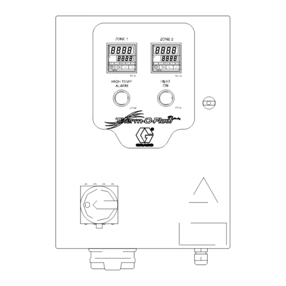
2-zone Accessory Control (243698)
4-zone Accessory Control (243699)
Refer to Graco form 309180, Installation and
Operation Guide for installation and operation
instructions.
Important Safety Instructions
Read all warnings and instructions in this
manual. Save these instructions.
See page 2 for Table of Contents.
4-Zone Accessory Control – 243699
GRACO INC. P.O. BOX 1441 MINNEAPOLIS, MN 55440-1441
Copyright 2000, Graco Inc. is registered to I.S. EN ISO 9001
Parts
2-Zone Accessory Control – 243698
TI0561
309213D
TI0562
Advertisement
Table of Contents

Subscribe to Our Youtube Channel
Related Manuals for Graco Therm-O-Flow Plus 243698


Summary of Contents for Graco Therm-O-Flow Plus 243698
- Page 1 Save these instructions. See page 2 for Table of Contents. TI0562 2-Zone Accessory Control – 243698 TI0561 4-Zone Accessory Control – 243699 GRACO INC. P.O. BOX 1441 MINNEAPOLIS, MN 55440-1441 Copyright 2000, Graco Inc. is registered to I.S. EN ISO 9001...
-
Page 2: Table Of Contents
..... . . Graco Factory P, I, and d Settings ... -
Page 3: Symbols
D Use the equipment only for its intended purpose. If you are uncertain about usage, call your Graco distributor. D Do not alter or modify this equipment. Use only genuine Graco parts and accessories. D Check the equipment daily. Repair or replace worn or damaged parts immediately. - Page 4 WARNING INJECTION HAZARD Fluid from the spray gun/dispense valve, hose leaks, or ruptured components can inject fluid into your body and cause extremely serious injury, including the need for amputation. Splashing fluid in the eyes or on the skin can also cause serious injury. D Fluid injected into the skin might look like just a cut, but it is a serious injury.
- Page 5 WARNING FIRE, EXPLOSION AND ELECTRIC SHOCK HAZARD Improper grounding, poor air ventilation, open flames, or sparks can cause a hazardous condition and result in fire, explosion, or electric shock and other serious injury. D Ground the equipment, the object being dispensed to, and all other electrically conductive objects in the dispense area.
-
Page 6: Overview
Overview Therm-O-Flow Plus Accessory Zone Controls Therm-O-Flow Plus Accessory Zone Controls are typically used to add more heat zones to an existing Therm-O-Flow Plus system. As an example, a user may have a Therm-O-Flow Plus system with six heat zones (pump, plate, 2 hose zones, and 2 gun/access zones). -
Page 7: Typical Installation
Typical Installation Master Air Valve (bleed-type) (required) G Extra Heated Hose (Zone Acc. 1) Pump Air Supply Hose Extra Dispense Valve (Zone Acc. 2) Fluid Compensator (Zone 4) Two Zone Controller Heated Hose (Zones 5 and 6) Electrical Control Panel (6 Zone) Hose Hanger Heated Ram Plate Assembly Manual Dispense Valve... -
Page 8: System Accessories And Modules
Typical Installation For operation and startup of a Therm-O-Flow Plus System Accessories and Modules unloader system, refer to Graco form 309180, Therm- Before you install the system you should be familiar O-Flow Plus Installation and Operation Guide. with the parts discussed in the subsequent para- graphs. -
Page 9: Installation
Installation Electrically Connect Hoses to the Electrical Control Panel WARNING FIRE HAZARD Only use hoses that have a maximum wattage less than or equal to 1250 watts. Using hoses with higher maxi- mum wattage could create a runaway temperature condition. Assemble the hose and gun components as needed. -
Page 10: Ground The System
Installation Ground The System To reduce the risk of static sparking, ground the pump, object being dispensed to, and all other spraying/dis- pensing equipment used or located in the spraying/dis- Ground the supply unit as instructed here and in the pensing area. -
Page 11: Connecting The Electrical Control Panel To A Power Source
Control (243698) For information about specific terminal locations and connections, see Control Panel Component Layout in Graco form 309085, and Electrical Setup in Graco form 309180, Therm-O-Flow Plus Installation and Operation Guide To connect the control panel to the electrical source: 1. -
Page 12: Check The Resistance Between The Supply Unit And The True Earth Ground
Installation Check the Resistance Between the Supply Sensor Resistance Checks Unit and the True Earth Ground WARNING ELECTROCUTION HAZARD WARNING To reduce risk of injury or damage to equipment, conduct these electrical FIRE, EXPLOSION, AND ELECTRIC checks with the main disconnect OFF. SHOCK HAZARD To reduce the risk of fire, explosion, or To verify the RTD sensors to be used with the 2- or... - Page 13 OFF position. information. 2. Make electrical resistance checks for the compo- nents. Refer to Control Panel Component Layout in Graco form 309085 for wiring diagram information. Table 1. Check Heater Resistance on 2-Zone Control (243698) Between...
-
Page 14: Overview Of The Temperature Controller Settings
Installation Overview of the Temperature Controller Settings The basic program settings for each temperature con- Table 5. Graco Factory P, I, and d Settings troller satisfy most application needs. The defaults ar Category Unit Voltage for using a hose on zones 1 and 3, and a gun on zones 2 and 4. -
Page 15: Operation
Temperature Alarm light is a visual indication only. It is lit when the zone temperature is above the SV of the control by a Graco preset value of 40_ F (22_ C). The 4-zone control (243699) has a power disconnect switch that provides power to the temperature controls. -
Page 16: Reading The Electrical Control Panel Indicators
Operation Reading the Electrical Control Panel Indicators Use the table and Fig. 5 below to read the indicators on the electrical control panel. Light Indicator: Indicator Meaning: Light is: Control On Power is on. Power is off. DIMLY LIT There may be a problem with the system power connections. Have connec- tions checked by a qualified electrician before attempting to start the sys- tem. -
Page 17: Resetting The Ground Fault Interrupt
Operation Resetting the Ground Fault Interrupt To reset the ground fault interrupt, have a qualified electrician: This control panel is equipped with a ground fault interrupt (GFPE) circuit breaker (Fig 6). If the discon- 1. Turn OFF the electrical disconnect on the electrical nect switch is ON, but all lights on the electrical control control panel. -
Page 18: Electrical Control Panel Troubleshooting
Electrical Control Panel Troubleshooting For more information, see the electrical control panel documentation. Problem Cause(s) Solution(s) Disconnect is ON, but no indica- The ground fault interrupt has been Reset the ground fault interrupt. tor lights are lit activated See procedure on page 17. One or more fuses has (have) been Replace the blown fuse(s) blown... -
Page 19: Parts
Parts Model 243698, Control, Electrical, 230/240 VAC, 2-Zone TC114 TC107 16-pin outlet TI0562 connector TI0562 309213... -
Page 20: Model243699, Control, Electrical, 230/240 Vac, 4-Zone
Parts Model 243699, Control, Electrical, 230/240 VAC, 4-Zone TC114 TC128 TC107 TC121 TI0561 (2) 16-pin outlet connectors TI0561 309213... - Page 21 Parts List Qty. in Device Manufacture Mfg # Graco # Panel 243698 2-Zone Control (230/240VAC) SSR109, 116 Carlo Gavazzi RJ1A60D20U (20A) 116204 Lamps for LT120, 128, (Lights on Door) Siemans 3B0A–BL1 116226 FU100, 101 Bussmann FNQ–R–15 Class CC 116214 FU107 Bussmann FNQ–R–1 Class CC...
-
Page 22: Spare Parts List
Dimensions Electrical Control Panel Mounting and Clearance Dimensions 12.0 IN. 8.8 IN. (305 MM) (224 MM) 10.5 IN. (237 MM) 14.5 IN. 16.0 in. (368 MM) (406 mm) 2-Zone Accessory Control 243698 TI0564 16.0 in. 8.8 IN. (406 mm) (224 MM) 14.5 IN. -
Page 23: Accessories
Accessories For a full selection of heated hoses and accessories, see Graco Product Data Sheet 325008. Cables 15’ Cable, 16 pin to 16 pin extension cable. Runs between controller and heated 196313 hose. 25’ Cable, 16 pin to 16 pin extension cable. Runs between controller and heated 196314 hose. - Page 24 Technical Data Description Specification Voltage 220/240 AC Frequency 50/60 Hz Power Phases Full Load Amps 2-zone #243695 11.0 amps 4-zone 3243699 15.5 amps TI0314 16-Pin Output Connector pinout designations 309213...
- Page 25 Notes 309213...
-
Page 26: Graco Standard Warranty
With the exception of any special, extended, or limited warranty published by Graco, Graco will, for a period of twelve months from the date of sale, repair or replace any part of the equipment determined by Graco to be defective.
Need help?
Do you have a question about the Therm-O-Flow Plus 243698 and is the answer not in the manual?
Questions and answers