Table of Contents
Advertisement
Quick Links
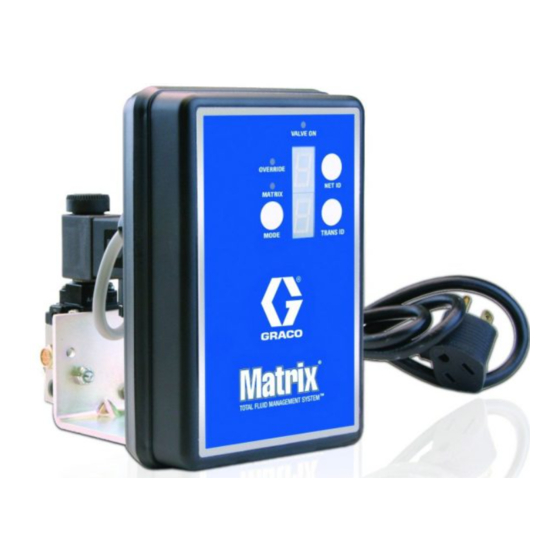
Pump Air Control (PAC) for
Matrix Systems
- For Control of Air to Pump Used with Matrix Meters -
Part: 247436
Includes global 120 - 240V (50 - 60 Hz) converter
Maximum Air Pressure 145 PSI (1 MPa, 10 bar)
Minimum Air Pressure 23 PSI (.17MPa, 1.7 bar)
Important Safety Instructions
Read all warnings and instructions in this
manual. Save these instructions.
Pump Air Control contains an RF devise with the following approvals:
FCC ID: TFB-FREESTAR
IC: 5969A-FREESTAR
Industry Canada Statement
The term "IC" before the certification/regis-
tration number only signifies that the
Industry Canada technical specifications
N14939 - FREESTAR
ZFMSM-101-1 (CEL) / FS24-100ST (LSR)
312417F
EN
ti11959a
Advertisement
Table of Contents

Related Manuals for Graco Matrix PAC 247436


Summary of Contents for Graco Matrix PAC 247436
- Page 1 Pump Air Control (PAC) for 312417F Matrix Systems - For Control of Air to Pump Used with Matrix Meters - Part: 247436 Includes global 120 - 240V (50 - 60 Hz) converter Maximum Air Pressure 145 PSI (1 MPa, 10 bar) Minimum Air Pressure 23 PSI (.17MPa, 1.7 bar) Important Safety Instructions Read all warnings and instructions in this...
- Page 2 Warnings Warnings The following warnings are for the setup, use, grounding, maintenance, and repair of this equipment. The exclama- tion point symbol alerts you to a general warning and the hazard symbol refers to procedure-specific risk. Refer back to these warnings. Additional, product-specific warnings may be found throughout the body of this manual where applicable.
-
Page 3: Installation
Installation Installation Remote Mounting Unless otherwise instructed, see F . 1 for reference numbers included in these instructions. The PAC controller can be mounted in a remote, secure location, away from the solenoid. The maximum dis- tance the two components can be separated is 75 feet. 1. - Page 4 Installation 11. Inside mini DIN solenoid connector, connect black wire to terminal labeled 1, white wire to terminal labeled 2 and green wire to GROUND. 12. Replace cover (f) and screw (e) on mini DIN sole- noid connection. 13. Reconnect mini DIN solenoid connection to sole- noid.
- Page 5 Registering the PAC Registering the PAC Mode Configuration 1. Press and hold MODE button (e) (F . 2) to select Matrix or Override mode. The LED next to selected mode will illuminate to indicate which mode, OVERRIDE (f) or MATRIX (g) is selected.
- Page 6 Registering the PAC Manual Override (A) The Manual Override Switch turns on air to the pump and allows you to prime the system without power. 1. Insert a small, flat screwdriver in slot of Manual Override Switch screw (A). 2. Rotate Manual Override Switch screw (A) clockwise approximately 1/4 turn.
-
Page 7: Wiring Diagram
Wiring Diagram Wiring Diagram See F . 4 for wiring diagrams. Grounding • The equipment must be grounded. Grounding reduces the risk of static and electric shock by pro- viding an escape wire for the electrical current due to static build up or in the event of a short circuit. •... -
Page 8: Error Codes
Troubleshooting Error Codes When an error code is present, LED’s will flash between NET ID and TRANS ID and ERROR CODE. To clear an Err1 or Err2 error, user must address the issue. To clear and Err3 or Err4 error, user must cycle between Matrix Mode to Override Mode and back. - Page 9 Repair Repair Pressure Relief Procedure 8. Connect air line inlet to port (15a). 9. Connect pump air inlet to port (15b). 10. Plug power cord in grounded outlet. This equipment will stay pressurized until the pressure has been manually relieved. To reduce the risk of serious injury from pressurized fluid, accidental spray from the dispense valve or splashing fluid, follow this Pressure Relief Procedure when ever you:...
- Page 10 Parts Parts Model 247436 Torque to 20 in.-lbs (2 N•m) Torque to 25 in.-lbs (3 N•m) Apply pipe sealant ti12325a 312417F...
-
Page 11: Technical Data
Parts Parts Part No. Description Part No. Description SCREW, thd forming, pnh 121071 SCREW, machine, #8-32 x 1-3/4, BOARD, circuit, assembly (PAC) model 247436 SEAL 120826 VALVE, solenoid COVER, enclosure 109466 NUT, lock, hex LABEL, overlay BRACKET, mounting 111881 MUFFLER CABLE, assembly 121045 CABLE, 3-wire (18 AWG) GASKET... -
Page 12: Graco Standard Warranty
With the exception of any special, extended, or limited warranty published by Graco, Graco will, for a period of two (2) years from the date of sale, repair or replace any part of the equipment determined by Graco to be defective.
Need help?
Do you have a question about the Matrix PAC 247436 and is the answer not in the manual?
Questions and answers