Table of Contents
Advertisement
Quick Links
Instructions
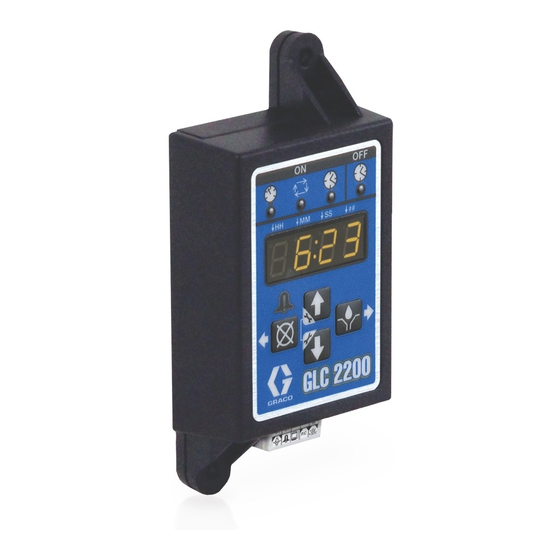
GLC 2200
Lubrication Controller
For controlling and monitoring an automated lubrication system. For professional use
only.
Not approved for use in explosive atmospheres or hazardous (classified) locations.
Model: 24N468
Important Safety Instructions
Read all warnings and instructions in this
manual before using the equipment. Save
these instructions.
3A2960G
EN
.
Advertisement
Table of Contents

Related Manuals for Graco 24N468


Summary of Contents for Graco 24N468
- Page 1 For controlling and monitoring an automated lubrication system. For professional use only. Not approved for use in explosive atmospheres or hazardous (classified) locations. Model: 24N468 Important Safety Instructions Read all warnings and instructions in this manual before using the equipment. Save...
-
Page 2: Table Of Contents
Mounting Hole Layout......28 Graco Standard Warranty..... 29... -
Page 3: Warnings
Warnings Warnings The following warnings are for the setup, use, grounding, maintenance, and repair of this equipment. The exclamation point symbol alerts you to a general warning and the hazard symbols refer to procedure-specific risks. When these symbols appear in the body of this manual or on warning labels, refer back to these Warnings. Product-specific hazard symbols and warnings not covered in this section may appear throughout the body of this manual where applicable. -
Page 4: Component Identification
Component Identification Component Identification Keypad, Display, and Icons Display (E) • A blinking field on the display indicates that the controller is in SETUP MODE. NOTICE To prevent damage to soft key buttons, do not press • In RUN MODE the numbers on the display will not the buttons with sharp objects such as pens, plastic blink. -
Page 5: Installation
Installation Installation Typical Installation The installation shown in F . 2 is only a guide for selecting and installing system components. Contact your Graco distributor for assistance in planning a system to suit your needs. Controller Capabilities Low Reservoir Level... -
Page 6: Installing The Lubrication Controller
Installation Installing the Lubrication System Configuration and Controller Wiring The System Configuration Diagrams (Fig 4 - 6), Sensor Wiring Diagrams (Fig 8 - 9), and Wiring Diagram (Fig 7) show typical Injector, Series Progressive and Dual Line lubrication system configurations. Automatic System Activation Hazard Refer to Table 1, 2, and 3 to determine the Required Unexpected activation of the lubrication system could... -
Page 7: System Configuration
Installation System Configuration Injector System Lubrication Points Injectors Pressure Switch Vent Valve Vent Line Pump & Reservoir Low Level Switch Pump On/Off GLC 2200 External Alarm . 4: Injector System 3A2960G... - Page 8 Installation Divider Valve System Master Divider Valve Cycle Switch Pump & Secondary Divider Valves Reservoir Low Level Switch GLC 2200 Pump On/Off External Alarm . 5: Divider Valve System 3A2960G...
- Page 9 Installation Dual Line System Lubrication Points Cycle Switch Reservoir Bi-flo Valves Vent Line Pump & Reservoir Low Level Switch GLC 2200 Pump On/Off External Alarm . 6: Dual Line System 3A2960G...
-
Page 10: Wiring Diagram
Installation Wiring Diagram Modes of Operation: Optional I/O Wiring Diagram Used with all modes of GLC2200 Operation 9A Fuse *Normally open vent valve for use with Injector-based systems Wiring Key Connector Identification Label Description Pump Alarm P/C +9V Low Level +30V Pressure/Cycle Switch Voltage Input... -
Page 11: Sensor Wiring
Installation Sensor Wiring DRY CONTACT SWITCH Configuration GLC 2200 SOURCE SWITCH - 2 or 3 Wire Type Configuration +VDC GLC 2200 -VDC 3A2960G... - Page 12 Installation . 10 3A2960G...
-
Page 13: Setup
Setup Setup Entering SETUP MODE To enter the PIN Code: 1. Press both the UP and DOWN arrow Press both the UP and DOWN arrow buttons together buttons for 3 seconds. for three seconds. NOTE: • If a button is not pushed for one (1) minute, the controller returns to the start of an OFF cycle. - Page 14 Setup Programming ON Duration Cycle Control (on:CY) ON Setup 1. Use the UP or DOWN arrow on:Pr, on:CY or on:ti appears on the display identifying button until on:CY displays. the function being programmed (see below). The LED illuminates below the related symbol on the controller to indicate the active function....
- Page 15 4. Press the ENTER button. The next number field to the right flashes and To determine the Backup Time, Graco recommends ver- the LED lights under SS; indicating it ifying the length of time to complete a typical cycle and is ready to program the seconds then double that value.
- Page 16 Setup Programming OFF TIME Duration Programming the Low Level Setting After setting the parameters for either Pressure (Pr), NOTE: If Low Level is not used (i.e., low level inputs are Cycle (CY) or Time (Ti) ON Modes, the OFF TIME or not connected), configuring the low level setting is still PUMP REST CYCLE must be set up.
- Page 17 This setting is intended for use with “paddle-style” low level sensors (such This setting configures the controller as the Graco G3 grease units).The into low level warning mode. This mode pump stops when low level occurs. To ensure a low level...
-
Page 18: Operation
Operation Operation Run Mode • Pump OFF time is shown in HH:MM (hours:minutes) or MM:SS if the time remaining is less than an hour. The controller is in RUN MODE providing the following circumstances are present: Cycle Mode: Pump ON The display alternates between the number of cycles •... -
Page 19: Series F And Later
Operation Timer Mode: Pump ON until TEST MODE is exited or 10 sequences are completed. If pressure or cycle feedback is The display indicates the amount of time remaining in selected, it will change to OFF when the SETUP the pump cycle, counting down the Pump ON time value parameters are met. - Page 20 Operation Alarm Types and Messages Alarm Type Error Code Description Things to Check/Do Refill lubrication reservoir. Low Level Low lubricant level If low level fault occurs unexpectedly verify wiring and programming setup. Inspect lubrication system for broken or plugged lines. Confirm pump is operating correctly.
-
Page 21: Advanced Programming (Series E Or Later Models Only)
Advanced Programming (Series E or later models only) Advanced Programming (Series E or later models only) The following Table Identifies each option and when it is used. Advanced Option Setting Format/ Description Why Use This? Lockout Secures setup modes with PIN Prevents unauthorized users from adjusting set- Code (Optional) tings. -
Page 22: Series F And Later
Advanced Programming (Series E or later models only) A1 - Setting Up PIN Code NOTE: If the pulse mode is enabled, the pump ON LED will blink for the duration of the pulse ON time while the A PIN Code can be programmed into the GLC 2200 to pump is on in RUN MODE. -
Page 23: End Of Product Life
End of Product Life End of Product Life At the end of the product’s useful life, dismantle and recycle it in a responsible manner. • Remove motors, circuit boards, LCDs (liquid crystal displays), and other electronic components. Recycle according to applicable regulations. •... -
Page 24: Troubleshooting
Troubleshooting Troubleshooting This equipment stays pressurized until pressure is manually relieved. To help prevent serious injury from pressurized fluid, such as skin injection, splashing fluid and moving parts, follow the Pressure Relief Procedure in the pump manual when you stop dispensing and before cleaning, checking, or servicing the equipment. -
Page 25: Program Settings
Program Settings Program Settings Description Modes of Operation Maximum/Minimum and Additional Comments PROGRAMMING ON, page 14 Pressure, Cycle, Time PRESSURE CONTROL, page 14 MM:SS (00:01 - 59:59) CYCLE CONTROL SETUP, page 14 Cycles: 01 to 99 BACKUP TIME, page 15 MM:SS (00:01 to 59:59) TIME CONTROL, page 14 MM:SS (00:01 to 59:59) -
Page 26: Parts
Parts Parts Ref. Description BOX, enclosure LABEL, control, overlay LABEL, serial, name LABEL, connector Accessories Related Kits Kit No. Description 24P314 GLC2200 Wiring Harness Kit 24P686 Single Connector Kit 24P687 Multiple Connector Kit 3A2960G... -
Page 27: Technical Specifications
Technical Specifications Technical Specifications Input Contact Power Source DC 9 - 30 VDC Power Consumption 1 Watt Cycle/Pressure Control Input (optional) 9 - 30 VDC, Normally open pressure or cycle switch Lubrication level (optional) Normally open level switch, closes upon low level Outputs Pump control Pump Control Voltage = Power Source... -
Page 28: Dimensions
Dimensions Dimensions Mounting Hole Layout Ø 0.2 in. (5.0 mm)- 4.92 in. (125.0 mm) 2.75 in. (70.0 mm) 1.38 in. (35.0 mm) 1.57 in. (40.0 mm) 5.53 in. (140.0 mm) 3A2960G... -
Page 29: Graco Standard Warranty
With the exception of any special, extended, or limited warranty published by Graco, Graco will, for a period of twelve months from the date of sale, repair or replace any part of the equipment determined by Graco to be defective. - Page 30 Original instructions. This manual contains English. MM 3A2960 Graco Headquarters: Minneapolis International Offices: Belgium, China, Japan, Korea GRACO INC. AND SUBSIDIARIES • P.O. BOX 1441 • MINNEAPOLIS MN 55440-1441 • USA Copyright 2012, Graco Inc. All Graco manufacturing locations are registered to ISO 9001. www.graco.com...
Need help?
Do you have a question about the 24N468 and is the answer not in the manual?
Questions and answers