Table of Contents
Advertisement
Quick Links
Instructions and Parts
ProBell®
ProBell® Air
ProBell®
Air Controllers
Air
For manual
manual or or or electronic
electronic air
For
For
manual
electronic
professional
professional use
professional
use only.
use
only. Not
only.
Important Safety
Important
Important
Safety Instructions
Safety
Read all warnings and instructions in this manual and in your
ProBell® Rotary Applicator manual. Save
100 psi (0.7 MPa, 7.0 bar) Maximum Air
Inlet Pressure
Controllers
Controllers
air control
control of of of a a a ProBell
ProBell rotary
air
control
ProBell
Not
Not approved
approved for
approved
for use
for
use in in in explosive
use
Instructions
Instructions
Save these
Save
PROVEN QUALITY. LEADING TECHNOLOGY.
rotary applicator
applicator as as
as part
rotary
applicator
explosive atmospheres
explosive
atmospheres or or or hazardous
atmospheres
these instructions.
these
instructions.
instructions.
3A3954D
part of of of a a a paint
paint coating
coating system.
part
paint
coating
hazardous locations.
hazardous
locations.
locations.
EN
system. For
For
system.
For
Advertisement
Table of Contents

Subscribe to Our Youtube Channel
Related Manuals for Graco ProBell 24Z221


Summary of Contents for Graco ProBell 24Z221
- Page 1 Instructions and Parts 3A3954D ProBell® ProBell® ProBell® Air Air Controllers Controllers Controllers For manual manual or or or electronic electronic air air control control of of of a a a ProBell ProBell rotary rotary applicator applicator as as as part part of of of a a a paint paint coating coating system.
-
Page 2: Table Of Contents
Contents Contents Contents Models............... 2 Repair..............22 Prepare for Service ........24 Related Manuals ..........2 Replace the Control Module......24 Warnings ............3 Replace the Trigger or Auxiliary Solenoid Valve ..........27 ProBell System Information ......... 5 Replace the Voltage to Pressure (V2P) System Connections and Features ...... -
Page 3: Warnings
Warnings Warnings Warnings Warnings The following warnings are for the setup, use, grounding, maintenance, and repair of this equipment. The exclamation point symbol alerts you to a general warning and the hazard symbols refer to procedure-specific risks. When these symbols appear in the body of this manual, refer back to these Warnings. Product-specific hazard symbols and warnings not covered in this section may appear throughout the body of this manual where applicable. - Page 4 Warnings WARNING WARNING WARNING EQUIPMENT EQUIPMENT EQUIPMENT MISUSE MISUSE MISUSE HAZARD HAZARD HAZARD Misuse can cause death or serious injury. • Do not operate the unit when fatigued or under the influence of drugs or alcohol. • Do not exceed the maximum working pressure or temperature rating of the lowest rated system component.
-
Page 5: Probell System Information
ProBell System Information ProBell System System Information Information ProBell ProBell System Information The ProBell Air Controller is an optional component in the ProBell Rotary Applicator system. The Electronic Air Controller sends air activation signals for the paint, dump, and solvent (cup wash) valves. It also electronically controls the inner and outer shaping air pressures. -
Page 6: System Connections And Features
System Connections and Features System Connections Connections and and Features Features System System Connections Features Air Line Line Port Label Label Electronic Manual Air Line Port Port Label Speed Speed Controller Speed Controller Controller Electronic Electronic Manual Manual Connections Connections Connections Air Controller Controller... -
Page 7: Component Identification
Component Identification Component Identification Identification Component Component Identification Electronic Air Air Controller Controller Electronic Electronic Controller Ref. Ref. Ref. Component Component Component Description Description Description Ref. Ref. Component Ref. Component Component Description Description Description Control Module Manages the operation Outer Shaping Shuts off the flow of the of all air controller Air Solenoid... - Page 8 Component Identification Manual Air Air Controller Controller Manual Manual Controller Ref. Component Component Description Ref. Component Component Description Ref. Ref. Component Description Description Ref. Ref. Component Description Description Control Module Manages the operation Outer Shaping Air Air pressure signal to of all air controller Regulator regulator M...
-
Page 9: Installation
Installation Installation Installation Installation Mount the the Controller Controller Mount Mount Controller Wall Wall Mounting Wall Mounting Mounting The pre-installed mounting brackets can be used to mount the controller on any flat wall. Mount the air controller in the non-hazardous area, as close to the To reduce the risk of fire or explosion, do not install applicator as possible, to minimize pressure loss in equipment approved only for a non-hazardous... - Page 10 Installation Manual Air Air Controller Controller Manual Manual Controller Cart Cart Cart Mounting Mounting Mounting For some ordering options, the air controller is mounted on the cart at the factory. If the cart was ordered separately, follow these steps: 1. Remove the four mounting brackets. Turn them so they are oriented horizontally.
-
Page 11: Ground The Controller
Installation Ground the the Controller Controller Ground Ground Controller The equipment must be grounded to reduce the risk of static sparking and electric shock. Electric or static sparking can cause fumes to ignite or explode. Improper grounding can cause electric shock. -
Page 12: Controller Connections
Be sure that your system • All air control is provided by the Graco Manual Air includes a power supply (sold separately). See Controller. ProBell System Information, page 5 for all system •... - Page 13 Auxiliary port for optional optocoupler wiring. Bearing Air — Use 8 mm (5/16 in) OD tube. Bearing Air Return — Use 4 mm (5/32 in) tubing. Black Graco CAN/Power (24VDC) White Dump Valve Trigger — Use 4 mm (5/32 in) tubing. Black Main Air Port —...
-
Page 14: Connect Air Lines
Graco Air Controllers are labeled with the same The air controllers (Manual or Electronic) reference letters as the applicator, for easier communicate to the rest of the system over Graco matching. CAN cables. Each component and the power supply must be on the Graco CAN network. The best... - Page 15 Controller Connections One Gun Gun Wiring Wiring Wiring Note For systems without an electrostatic controller (CC), connect the system logic controller directly to an open CAN port on either the speed controller (EE) or electronic air controller (BB). Two Gun Gun Wiring Wiring Wiring...
-
Page 16: Connect Power
Wiring Paint Trigger Input One power supply is required in the Graco CAN The Paint Trigger Input provides a means to signal network, typically mounted on the bottom of the the System Logic Controller to activate the paint Speed Controller, or the Manual Air Controller. -
Page 17: Wiring The Optional Interlock Input
Optional Interlock Input The Optional Interlock Input uses an optocoupler to protect the Graco ProBell air control box from outside voltages. The Optional Interlock Input provides a means to signal the System Logic Controller to stop the • Optocoupler ports 13+ and 14 are wired to the ProBell system. -
Page 18: Troubleshooting
Solution Solution Type Type Type CAP1 Alarm Commu- The System Logic • Verify Graco CAN connection on bottom of the Air nication Controller has lost Controller. CAP2 Error Air communication • Check status LEDs on the control module. Control with the air controller. - Page 19 Troubleshooting Table 4 4 4 Electronic Electronic Shaping Shaping Air Air Errors Errors Table Table Electronic Shaping Errors Event Name Description Code Code Code Event Event Name Name Description Description Solution Solution Solution Type Type Type P111 or Alarm Pressure Low, Actual air pressure 1 Verify shaping air 1 (inner) hose is not P112...
- Page 20 Troubleshooting Code Event Name Description Solution Code Code Event Event Name Name Description Description Solution Solution Type Type Type P611 or Alarm Sensor The returned value of the • Replace cable 17K902. P612 Disconnected, pressure sensor for inner • Replace volltage to pressure regulator Inner Shaping shaping air is zero P6Y1 or...
- Page 21 Troubleshooting Table 7 7 7 Maintenance Maintenance Advisories Advisories Table Table Maintenance Advisories Event Name Description Remedy Code Code Code Event Event Name Name Description Description Remedy Remedy Type Type Type MD11 Advisory Maintenance Valve Gun 1 paint valve is due for Paint Gun 1 maintenance.
-
Page 22: Repair
Repair Repair Repair Repair Electrical Electrical Electrical Schematics Schematics Schematics Figure 4 Manual Air Controller 3A3954D... - Page 23 Repair Figure 5 Electronic Air Controller 3A3954D...
-
Page 24: Prepare For Service
Repair Prepare for for Service Service Replace the the Control Control Module Module Prepare Prepare Service Replace Replace Control Module Follow these instructions to replace the control module (Refs. 2 and 6). Order Kit 25C423, which includes the module and the necessary software token. - Page 25 Repair Figure 6 Replace Control Module, Electronic Air Controller Figure 7 Replace Control Module, Manual Air Controller 3A3954D...
- Page 26 Repair Front Side Side Back Side Side Front Front Side Back Back Side Table Table Table 8 8 8 Electronic Electronic Electronic Air Air Controller Controller Controller Module Purpose Module Module Purpose Purpose System System System Connection Connection Connection Connection Connection Connection Terminal Blocks 1 and 3...
-
Page 27: Valve
Repair Replace the the Trigger Trigger or or or Auxiliary Auxiliary Solenoid Solenoid Valve Valve Replace Replace Trigger Auxiliary Solenoid Valve 1. Follow directions at Prepare for Service, page 3. Remove the solenoid (34). 2. Disconnect the electrical wires. See the following 4. - Page 28 Repair Replace the the Voltage Voltage to to to Pressure Pressure (V2P) (V2P) Regulator Regulator Replace Replace Voltage Pressure (V2P) Regulator Note 8. Use screws (40a) to attach the new regulator (41) to the bracket. This part is not used on Manual Air 9.
-
Page 29: Replace A Shaping Air Solenoid Valve
Repair Replace a a a Shaping Shaping Air Air Solenoid Solenoid Valve Valve Replace Replace Shaping Solenoid Valve Note 10. Test the new solenoid using maintenance screens on the system logic controller. See This part is not used on Manual Air manual 3A3955, System Logic Controller, for Controllers. -
Page 30: Replace The Pressure Switch
Repair Replace the the Pressure Pressure Switch Switch Replace a a a Pressure Pressure Gauge Gauge Replace Replace Pressure Switch Replace Replace Pressure Gauge Note Note This part is not used on Electronic Air This part is not used on Electronic Air Controllers. -
Page 31: Regulator
Repair Replace a a a Pressure Pressure Regulator Regulator Replace the the Bearing Bearing Air Air Filter Filter Replace Replace Pressure Regulator Replace Replace Bearing Filter Note Note This part is not used on Electronic Air This part is not used on Electronic Air Controllers. -
Page 32: Parts
Parts Parts Parts Parts Electronic Air Air Controller Controller (Model (Model 24Z222) 24Z222) Electronic Electronic Controller (Model 24Z222) 3A3954D... - Page 33 Parts Electronic Air Controller (Model 24Z222) 3A3954D...
- Page 34 Parts Part Part Part Description Description Description Part Part Part Description Description Description — — — ENCLOSURE — — — COVER, wire duct 289697 MODULE, base 100139 PLUG, pipe — — — SCREW, machine, pan 17D921 BRACKET, regulator head, 6–32 x 1 1/2 in. 17G386 REGULATOR, —...
-
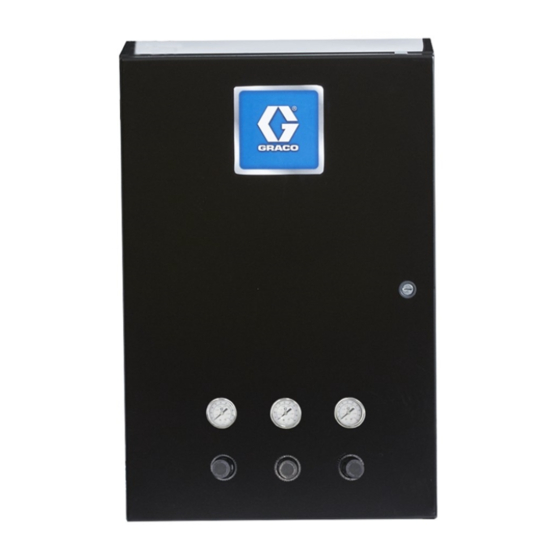
Page 35: Manual Air Controller (Model 24Z221)
Parts Manual Air Air Controller Controller (Model (Model 24Z221) 24Z221) Manual Manual Controller (Model 24Z221) 3A3954D... - Page 36 Parts Manual Air Controller (Model 24Z221) 3A3954D...
- Page 37 Parts Part Part Part Description Description Description Part Part Part Description Description Description — — — ENCLOSURE — — — MARKER, terminal block, 31–40 289697 MODULE, base 111987 CONNECTOR, strain relief 1 — — — SCREW, machine, pan — — — BRACKET, mounting, head, 6–32 x 1 1/2 in.
- Page 38 Parts Part Part Part Description Description Description Replacement safety labels, tags, and cards are ▲ available at no cost. — — — FITTING, straight, 1/2 x 3/8 Tube 061513 TUBE, 1/2 OD 2 ft. 3A3954D...
-
Page 39: Kits And Accessories
Kits and Accessories Kits and and Accessories Accessories Kits Kits Accessories Power Supply Supply Kit Kit 24Z224 24Z224 Power Power Supply 24Z224 Ref. Ref. Ref. Part Part Part Description Description Description Qty. Qty. Qty. 100518 WASHER, flat 103181 WASHER, lock 141395 SCREW, machine, pan head, #6–32 x 0.375 in. - Page 40 — — — Controller TOKEN, programming 130193 CABLE, CAN, 0.5 m 17M465 TOKEN, software upgrade 121901 SUPPRESSOR — — — SCREW, machine, 6–32 x Graco CAN CAN Cables Cables Graco Graco Cables 1–1/2 100272 WASHER, lock, #6 Part Part Part...
-
Page 41: Technical Specifications
Technical Specifications Technical Specifications Specifications Technical Technical Specifications ProBell Air Controller Metric Maximum air working pressure 100 psi 0.69 MPa, 7.0 bar Turbine speed, maximum 60,000 rpm operating Bearing air, minimum required 70 psi 0.5 MPa, 5.0 bar 1/2” npt Air Connection Maximum Operating Voltage 24 VDC, 2.5A... - Page 42 Graco to be defective. This warranty applies only when the equipment is installed, operated and maintained in accordance with Graco’s written recommendations. This warranty does not cover, and Graco shall not be liable for general wear and tear, or any malfunction, damage or wear caused by faulty installation, misapplication, abrasion, corrosion, inadequate or improper maintenance, negligence, accident, tampering, or substitution of non-Graco component parts.
Need help?
Do you have a question about the ProBell 24Z221 and is the answer not in the manual?
Questions and answers