Table of Contents
Advertisement
Quick Links
- 1 Manual Conventions
- 2 Fluid Pressure Regulators
- 3 Back Pressure Regulators
- 4 Cleaning and Repair
- 5 Mechanical Fluid Pressure Regulators Part Numbers 233759 and 234267
- 6 Mechanical Fluid Pressure Regulators Part Numbers 233757, 233774, 234263, 234273 and 17L324
- 7 Pneumatic Fluid Pressure Regulators Part Numbers 233773, 233809, 234272, and 234256
- 8 Technical Data
- Download this manual
Instructions
Low Pressure
Fluid Regulators
For use in air-assisted spray systems to ensure accurate, positive control of fluid pressure
to a spray gun, low pressure dispensing valve, or atomizing head.
For professional use only.
Important Safety Instructions
Read all warnings and instructions in this manual.
Save these instructions.
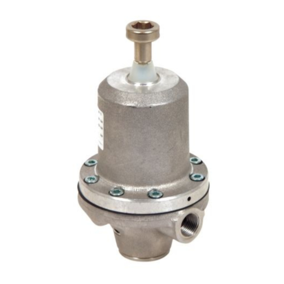
Model 233757 Shown
309474U
II 2 G
Advertisement
Table of Contents

Related Manuals for Graco P20-VM


Summary of Contents for Graco P20-VM
- Page 1 Instructions Low Pressure Fluid Regulators 309474U For use in air-assisted spray systems to ensure accurate, positive control of fluid pressure to a spray gun, low pressure dispensing valve, or atomizing head. For professional use only. Important Safety Instructions Read all warnings and instructions in this manual. Save these instructions.
-
Page 2: Table Of Contents
Mounting Dimensions ..... . 21 Graco Warranty ......22... -
Page 3: List Of Models
Regulated Pressure Range 233757 P20-VM Mechanical, 580 psi (4000 kPa, 40 bar) 15-290 psi 234263 P20-VM npt fluid pressure (100-2000 kPa, 1-20 bar) 17L324 A P20-VM npt Mechanical, 1500 psi (10.3 MPa, 103 bar) 15-290 psi (100-2000 kPa, fluid pressure 1-20 bar). - Page 4 Read all instruction manuals, tags, and labels before operating the equipment. • Use the equipment only for its intended purpose. If you are not sure, call your Graco distributor. • Do not alter or modify this equipment. Use only genuine Graco parts and accessories.
-
Page 5: Introduction
Introduction Introduction A fluid pressure regulator is used in air spray systems to Fluid Pressure Regulators ensure accurate, positive control of fluid pressure to an Models 233757, 233759, 233774, 234263, 234267, air spray gun or to a low pressure dispensing valve or 234273, and 17L324 (F . - Page 6 Introduction Adjustment screw Spring Diaphragm Fluid Outlet Fluid Inlet (to gun) (from pump) Valve plunger Valve ball and seat TI1772B Fig. 2. Cutaway of Mechanical Fluid Pressure Regulator Air inlet Fluid Inlet Fluid Outlet (from pump) Diaphragm (to gun) Valve plunger Valve ball and seat TI1771B Fig.
-
Page 7: Installation
Connect the fluid line for installing a system. They do not depict actual system to the gun to the regulator’s outlet. designs. Consult your Graco distributor for assistance in designing a system that meets your specific requirements. - Page 8 Installation Air to Fluid Air to Regulator Pump Air to TI1766A Fig. 5. Low pressure, non-circulating system, pneumatic fluid regulator Fluid regulator Air line filter Air spray gun Bleed-type air shut-off valve Air regulator for fluid regulator Air regulator for pump and gun Pump ground wire Pump 309474U...
- Page 9 Installation Fluid Air to Air to Fluid Air to Back Fluid Regulator Pressure Regulator Fluid to gun Fluid return from gun TI1768A Fig. 6. Low Pressure circulating system, pneumatic fluid regulator and back pressure regulator Air regulator for fluid regulator Air line filter Fluid shutoff valve Bleed-type air shut-off valve...
-
Page 10: Operation
Operation Operation Flush Before First Use Mechanical Regulator 1. Back out the adjustment screw until there is no Your pressure regulator has been tested in the factory spring pressure. with an anti-corrosion liquid. Before using the regulator, thoroughly flush the system with a solvent to remove 2. -
Page 11: Troubleshooting
Troubleshooting Troubleshooting Relieve the pressure (page 10) before checking or repairing the equipment. To repair the regulator, refer to page 12. Problem Cause Solution Drop in fluid outlet pressure. Ruptured diaphragm (15). Replace diaphragm. Air escaping (pneumatic regulators Check air hose and connections. only). -
Page 12: Maintenance
Maintenance Maintenance Flushing 1. Relieve all air and fluid pressure in the system. 2. Remove the regulator from the system. Flush before changing colors, at the end of the day, before storing, and before repairing the equipment. 3. Disassemble the regulator (see the parts drawings on pages 13 through 18). -
Page 13: Parts
Parts Parts Mechanical Fluid Pressure Regulators Part Numbers 233759 and 234267 Torque to 6 N•m (53 in-lb). Torque to 2 N•m (18 in-lb). TI1753A Fill internal cavity with grease. Used only on non-npt model 233759. Torque to 5 N•m (44in-lb). Apply medium-strength (blue) thread locker to the threads. -
Page 14: Mechanical Back Pressure Regulators Part Numbers 233812 And 234258
Parts Mechanical Back Pressure Regulators Part Numbers 233812 and 234258 Torque to 6 N•m (53 in-lb). Torque to 2 N•m (18 in-lb). Fill internal cavity with grease. Used only on non-npt model 233812. Torque to 5 N•m (44in-lb). Apply medium-strength (blue) thread locker to the threads. -
Page 15: Mechanical Fluid Pressure Regulators Part Numbers 233757, 233774, 234263, 234273 And 17L324
Parts Mechanical Fluid Pressure Regulators Part Numbers 233757, 233774, 234263, 234273 and 17L324 Torque to 4-5 N•m (35-44 in-lb). Torque to 2 N•m (18 in-lb). For 17L324, torque to 5.6 N•m (50 in-lb). Torque to 5 N•m (44 in-lb). TI1751A Grease OD. -
Page 16: Mechanical Back Pressure Regulators Part Numbers 233758, 233811, 233950, 234255, 234261, And 234262
Parts Mechanical Back Pressure Regulators Part Numbers 233758, 233811, 233950, 234255, 234261, and 234262 Torque to 4-5 N•m (35-44 in-lb). Torque to 2 N•m (18 in-lb). Torque to 5 N•m (44 in-lb). Grease OD. Used only on non-npt models 233758, 233950, and 233811. Not used on models 233811 and 234255. -
Page 17: Pneumatic Fluid Pressure Regulators Part Numbers 233773, 233809, 234272, And 234256
Parts Pneumatic Fluid Pressure Regulators Part Numbers 233773, 233809, 234272, and 234256 Torque to 4-5 N•m (35-44 in-lb). Torque to 2 N•m (18 in-lb). Torque to 5 N•m (44 in-lb). Grease OD. Used only on non-npt models 233773 and 233809. Used only on npt models 234272 and 234256. -
Page 18: Pneumatic Back Pressure Regulators Part Numbers 233810 And 234257
Parts Pneumatic Back Pressure Regulators Part Numbers 233810 and 234257 Torque to 4-5 N•m (35-44 in-lb). Torque to 2 N•m (18 in-lb). Torque to 5 N•m (44 in-lb). Grease OD. Used only on non-npt model 233810. Used only on npt model 234257. TI11250a Apply medium-strength (blue) thread locker to the threads. -
Page 19: Technical Data
Technical Data Technical Data Category Data Maximum Fluid Inlet Pressure 233757, 233773, 233774, 233809, 234256, 234263, 234272, 234273: 580 psi (Fluid Pressure Regulators) (4000 kPa, 40 bar) 17L324: 1500 psi (10.3 MPa, 103 bar) 233759, 234267: 1015 psi (7000 kPa, 70 bar) Maximum Permanent Supply 233758, 233810, 234257, 234262: 145 psi (1000 kPa, 10 bar) Pressure (Back Pressure... -
Page 20: Accessory Gauges
Accessory Gauges Accessory Gauges Part Gauge Part Gauge 233758 118338 233774 118338 234262 118338 243273 118338 233950 118338 233757 118338 234261 118338 234262 118338 233811 118338 233759 118339 234255 118338 234267 118339 233812 118339 234773 118338 234258 118339 234272 118338 233810 118338 233809... -
Page 21: Mounting Dimensions
Mounting Dimensions Mounting Dimensions Part Thread Dimension A 233757 24 mm (0.95 in.) 234263 17L324 233758 24 mm (0.95 in.) 234262 233759 24 mm (0.95 in.) 234267 233773 24 mm (0.95 in.) 234272 233774 24 mm (0.95 in.) 234273 233809 24 mm (0.95 in.) 234256 233810... -
Page 22: Graco Warranty
With the exception of any special, extended, or limited warranty published by Graco, Graco will, for a period of twelve months from the date of sale, repair or replace any part of the equipment determined by Graco to be defective.
Need help?
Do you have a question about the P20-VM and is the answer not in the manual?
Questions and answers