Sign In
Upload
Download
Table of Contents
Contents
Add to my manuals
Delete from my manuals
Share
URL of this page:
HTML Link:
Bookmark this page
Add
Manual will be automatically added to "My Manuals"
Print this page
×
Bookmark added
×
Added to my manuals
Manuals
Brands
INIM Manuals
Control Panel
SmartLoop Series
Installation manual
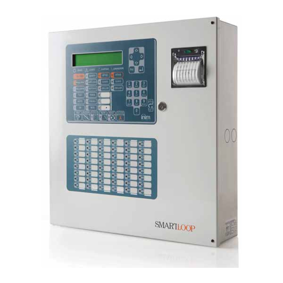
INIM SmartLoop Series Installation Manual
Analogue fire alarm control panel
Hide thumbs
Also See for SmartLoop Series
:
Programming manual
(44 pages)
1
2
Table Of Contents
3
4
5
6
7
8
9
10
11
12
13
14
15
16
17
18
19
20
21
22
23
24
25
26
27
28
29
30
31
32
33
34
35
36
37
38
39
40
41
42
43
44
45
46
47
48
49
50
51
52
53
54
55
56
57
58
59
60
page
of
60
Go
/
60
Contents
Table of Contents
Troubleshooting
Bookmarks
Table of Contents
Chapter 1 Introduction
Copyright
European Directive Compliance
Table of Contents
Application and Use
Other Parts of the System
In Order to Validate the IMQ-SECURITY SYSTEMS Certification, and in Compliance with EN54-2 Regulations
About the Smartloop Fire Alarm Panel Series
Description of the Models
Features
General Information
Documentation Supplied
Manual Details
Firmware Information
Operator Classification - Access Levels
Intellectual Property Rights
Disclaimer
Recommendations
Testing the System
Note to the Installer
Technical Support
Conventions
Device Identification Details
Warranty
Safety Laws
Device Management
Product Handling and Storage
Environmental Conditions
Unpacking the Device
Technical Description
Panel
The Motherboard
LED Panel
Technical Specifications
Accessory Devices
Attachment Boards
Smartloop/Prn Printer
The Smartletusee/Lcd and Smartletusee/Led Repeater Panels
Installation
Choosing the Mounting Location
Installation Flow, Guidelines and Testing
Connecting the Smartloop/Prn Printer Module
Connections
Note to the Installer Regarding Wiring and Connection Compliancy
About the Circuitry
Loop Connections
NAC Outputs (Notification Application Circuit)
Terminal
AUX Output
AUX-R Output
Alarm Relay
Fault Relay
Connecting Devices to the RS485 BUS
Connecting the Smartloop/Net Module
Connecting the Smartloop/Inout Board
Connecting to a PC
Connecting a Smartlan (or Smartlan/Sf) Equipped Control Panel to a PC
Connecting a Serial Printer
Batteries
Connecting the Thermal Probe
Connecting the Mains Power Source
Powering up the System
Testing Wiring Integrity
First Power up
Maintenance
Troubleshooting
Fault NAC, Alarm or Fault Output Trouble
LOOP Fault
Fault on Devices Connected to the RS485 BUS
Battery Fault
Smartloopnet Fault
Appendix A Enea Devices
Appendix B Argus Devices
Appendix C Apollo Devices
Appendix D Order Codes
Appendix D Notes
Advertisement
Quick Links
1
Maintenance
Download this manual
See also:
Programming Manual
SmartLoop
Analogue fire alarm control panel
Installation manual
EN 54-2
EN 54-4
0051-CPD-0225
0051-CPD-0226
0051-CPD-0227
0051-CPD-0228
0051-CPD-0231
0051-CPD-0232
Table of
Contents
Previous
Page
Next
Page
1
2
3
4
5
Advertisement
Table of Contents
Need help?
Do you have a question about the SmartLoop Series and is the answer not in the manual?
Ask a question
Questions and answers
Related Manuals for INIM SmartLoop Series
Control Panel INIM SmartLoop2080/S Programming Manual
Analogue fire alarm control panel (44 pages)
Control Panel INIM SmartLight Series Installation And Programming Manual
Analogue fire alarm control panel, extinguishant system control panel (72 pages)
Control Panel INIM SmartLoop2080/G Installation Manual
Analogue fire alarm control panel (60 pages)
Control Panel INIM SmartLoop1010/G Installation Manual
Analogue fire alarm control panel (60 pages)
Control Panel INIM SMARTLOOP 0051-CPR-0225 Manual
Analogue fire alarm control panel (44 pages)
Control Panel INIM SmartLine 0051 Series User Manual
Conventional fire detection control panel (12 pages)
Control Panel INIM PREVIDIA COMPACT Installation Manual
Analog-addressable fire alarm control panel, extinguishant system control panel, alarm transmission and fault warning routing equipment (28 pages)
Control Panel INIM SmartLiving 505 Installation And Programming Manual
Anti-intrusion control panels and security systems (2 pages)
Control Panel INIM Previdia Ultra Installation Manual
Control panel for fire detection and alarm (76 pages)
Control Panel INIM GameOver SmartLiving 505 Installation And Programming Manual
(100 pages)
Control Panel INIM PREVIDIA Ultra Manual To Networking
Control panels for fire detection and alarm, fire extinction and voice-evacuation systems (24 pages)
Control Panel INIM PREVIDIA ULTRA User Manual
Control panel for fire detection and alarm, fire extinction and voice-evacuation systems (40 pages)
Control Panel INIM Prime060S User Manual
Anti-intrusion control panels and security systems (72 pages)
Control Panel INIM PREVIDIA ULTRAVOX Instruction Manual
Control panel for fire detection and alrm and voice-evacuation systems (16 pages)
This manual is also suitable for:
Smartloop2080/g
Smartloop1010/s
Smartloop2080/s
Smartloop1010/p
Smartloop2080/p
Smartloop1010/g
Table of Contents
Save PDF
Print
Rename the bookmark
Delete bookmark?
Delete from my manuals?
Login
Sign In
OR
Sign in with Facebook
Sign in with Google
Upload manual
Upload from disk
Upload from URL


Need help?
Do you have a question about the SmartLoop Series and is the answer not in the manual?
Questions and answers