Table of Contents

Subscribe to Our Youtube Channel
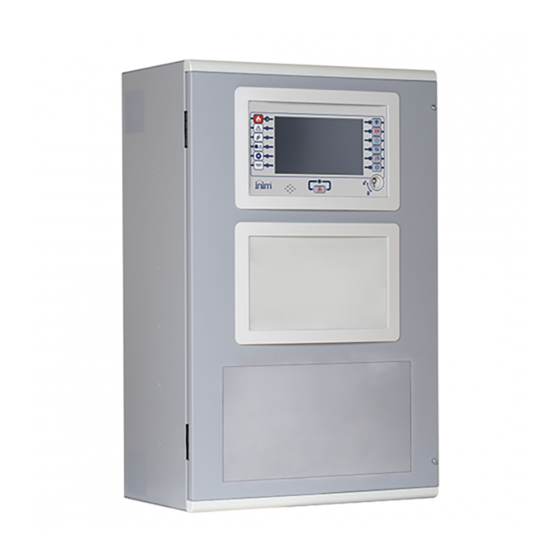
Related Manuals for INIM Previdia Ultra


Summary of Contents for INIM Previdia Ultra
- Page 1 EN 54-2 EN 54-4 Installation manual EN 54-16 EN 54-21 0051 EN 12094-1 0051-CPR-2741 0051-CPR-2826 0051-CPR-2827 CONTROL PANEL FOR FIRE DETECTION AND ALARM, FIRE EXTINCTION AND VOICE-EVACUATION SYSTEMS INSTALLATION MANUAL...
-
Page 2: Warranty
In no case can INIM Electronics s.r.l. be held responsible or liable by the buyer or any other person for any loss or damage, direct or indirect, consequential or incidental. -
Page 3: Table Of Contents
Control Panels in an IP network....................14 Inim Cloud fire ..........................14 List of Previdia Ultra system components ................14 Chapter 3 Description of the Previdia Ultra system parts............ 16 Basic control panel models......................16 PRCAB+, cabinet ..........................21 PRCABRK+, accessories for mounting the cabinet ............. 23 FPMCPU, front-plate CPU module and repeater.............. - Page 4 Fire detection and extinguishing system IFAMAMP internal module wiring ....................62 4.10 IFAMIDANET internal module wiring ..................64 4.11 IFAMFFT internal module wiring ....................65 4.12 IFM2L internal module wiring - loop connection ..............65 4.13 IFMNET internal module wiring - Hornet+ network connection........66 4.14 IFM4R internal module wiring ....................
-
Page 5: Chapter 1 General Information
INIM Electronics brand. Supplied Documentation Previdia Ultra User’s Manual: contains the identification of the parts on the front plate and the end-user operating instructions for use. Previdia Ultra control panel Installation Manual: contains the technical specifications of the Previdia Ultra control panels and the mounting, installation and wiring instructions. -
Page 6: Operator Classification - Access Levels
Fire detection and extinguishing system 1.3.1 Terminology Control panel, System, Device: The main supervisory unit or any constituent part of the fire detection system. Left, Right, Behind, Above, Below: Directions as seen by the operator when directly in front of the mounted device. Qualified personnel: Personnel whose training, expertise and knowledge of the products and laws regarding security systems, are capable of creating, in accordance with the requirements of the purchaser, the most suitable solution for the protected premises. -
Page 7: Ce Mark
- Superuser level, las for the previous one, with the added possibility of replacing a loop device and registering control panels to their account with the Inim Cloud service - Maintenance level, same as the previous level with the added possibility of stopping the valve pulse for those... - Page 8 PASS 1.5.2 Directive 2014/53/EU Hereby INIM Electronics S.r.l. declares that the above mentioned control panel models with the optional modules comply with the essential requirements and other relevant provisions established by directive 2014/53/EU. Following paragraph explains how to download the complete Declaration of Conformity.
- Page 9 Declarations of Performance, Declarations of Conformity and Certificates concerning to INIM Electronics S.r.l. products may be downloaded free of charge from the web address www.inim.biz, getting access to Extended Access and then selecting “Certifications” or requested to the e-mail address info@inim.biz or requested by ordinary mail to the address shown in the paragraph 1.5.1.
-
Page 10: Chapter 2 General Description
General Description Previdia Ultra System Previdia Ultra is a modular system for constructing fire detection, alarm, exinguishing and voice alarm systems. A voice evacuation system (commonly named “EVAC” standing for Emergency Voice Alarm and Communication) is a system that uses loudspeakers and amplifiers with characteristics suitable for alerting building occupants to imminent danger in the event of a fire. - Page 11 Installation manual Previdia-Ultravox • control panel in single cabinet with fire detection and voice evacuation functions The control panel includes the modules: - FPMCPU, main CPU unit with display - FPAMIAS: control panel with display for EVAC/PA voice functions - IFAMPSU, power-supply module capable of supplying current up to 1KWatt at 27.6V - IFAMEVAC: audio matrix module for signals processing - IFAMAMP: 250W audio amplifier module...
- Page 12 The Previdia Ultra control panel can be mounted in up to 4 cabinets that can be affixed together. In a system with more than one cabinet, the maximum number of modules is as follows:...
-
Page 13: Single Cabinet Control Panel
IDANet Through IDANet network-connection technology, Previdia Ultra control panels can be connected in a ring via a CAT5 ethernet cable (up to 100m) or optical fiber (by means of an appropriate SFP module according to the type of fiber used). -
Page 14: Control Panels In An Ip Network
Each cluster, equipped with at least one FPMCPU control panel, can be connected to the Inim cloud, allowing you to take advantage of the following features: •... - Page 15 Installation manual • IFAM internal modules: - IFAMPSU 1KW power-supply module - IFAMEVAC Audio matrix module - IFAMAMP 250W audio amplifier module - IFAMIDANET Module for the connection in IDANET network - IFAMFFT Module with 4 lines for emergency telephones •...
-
Page 16: Chapter 3 Description Of The Previdia Ultra System Parts
Fire detection and extinguishing system Chapter 3 Description of the Previdia Ultra system parts Basic control panel models The Previdia Ultra system includes three basic control panel models, distinct from each other with regard their available functions and assembled modules: - Previdia-Ultravox - Previdia-Vox... - Page 17 IFAMPSU power-supply module module (paragraph 3.5) FPAMIAS (paragraph 3.7) (paragraph IFAMAMP module Housing for the PTT microphone (included) 3.10) (paragraph IFAMEVAC module Back 3.9) (paragraph IFM2L module Wall-mount screw locations 3.13) Cable entry Description of the Previdia Ultra system parts...
- Page 18 • 5 ferrites (1 for the mains cable, 2 for the speaker lines and 2 for the OUT1/2 outputs) • bag with components for line terminations • Hole covers (inserted) • installation guide • user’s manual Description of the Previdia Ultra system parts...
- Page 19 Previdia-Ultra216 comes with: • battery connection wire • 2 metal keys • 1 ferrite for the mains cable • bag with components for line terminations • Hole covers (inserted) • installation guide • user’s manual Description of the Previdia Ultra system parts...
- Page 20 433 x 677 x 258 mm Weight 20 Kg Protection grade IP30 2 x 12V 38Ah, NP38-121 or Accepted Batteries 2 x 12V 24Ah, NPL24-12I or 2 x 12V 17 Ah, NP 17 -12-FR or equivalent Description of the Previdia Ultra system parts...
-
Page 21: Prcab+, Cabinet
• CAN DRIVE+ bar (inserted) • Hole covers (inserted) • 2 bolts for affixing cabinets together • a CAN bus cable and a flat cable for cabinet interconnection • ground connection wire • Instructions manual Description of the Previdia Ultra system parts... - Page 22 Screw locations for the cover Connection points for IFAMPSU screws power supply Back Fixing holes for DIN rail Fixing holes for PRCAB- Wall-mount screw locations Boostfan Cable entry Backup battery housing Description of the Previdia Ultra system parts...
-
Page 23: Prcabrk+, Accessories For Mounting The Cabinet
The PRCABRK+ kit allows you to mount the cabinet to a 19” rack by means of two support brackets at each side of the cabinet. PRCABRK come complete with: • 4 nuts with washers • Instructions manual Description of the Previdia Ultra system parts... -
Page 24: Fpmcpu, Front-Plate Cpu Module And Repeater
• backup unit • remote repeater user-interface FPMCPU comes with: • CAN BUS cable • 6 screws with washers for securing the module • 2 system access keys • 2 ferrites • Instructions manual Description of the Previdia Ultra system parts... - Page 25 FPM-CPU module - technical specifications Supply voltage 19-30V Operating temperature from -5°C to +40°C stand-by 130mA Consumption @ maximum 140mA 27.6V mains fault 110mA Maximum voltage on RS485-REPEATER 1A @27.6V Maximum voltage on RS485-BMS 1A @27.6V Description of the Previdia Ultra system parts...
-
Page 26: Fpamias, Front-Plate Voice Module
It deals with the management and coordination of the various voice modules. A single Previdia Ultra control panel can house only one of these modules. Mounts to the front plate and, if housed in the upper opening, connects to the CAN DRIVE+ bar. If housed in the lower opening, it connects to the FPMCPU module in the upper opening. -
Page 27: Fpmled, Fpmledprn, Led And Printer Front-Plate Module
• Instructions manual Thermal printer Mounting screw locations Connector for the CAN drive bar or other front- plate module Connector for front-plate module Mini USB port Label with firmware revision of the module Description of the Previdia Ultra system parts... -
Page 28: Ifampsu, Internal Power-Supply Module
• Instructions manual Status LED AC Mains input terminals Hole for the Earth bar screw Mini USB port and for the Earth conductor Jumper connectors for enablement of Battery Battery connector the ground-fault test Description of the Previdia Ultra system parts... - Page 29 UL94-V1 flame class enclosure or higher Maximum voltage charge adapted to temperature Batteries Battery charger Maximum internal resistance of battery 0,1Ohm (Ri Max) Battery shutdown voltage 19.5V Operating temperature from -5°C to +40°C Isolation class Description of the Previdia Ultra system parts...
-
Page 30: Ifm24160, Internal Power-Supply Module
Hole for the grounding bar screw and for the wire ground-fault test with the eyelet terminal 230/ OUT1 Input voltage selector 115 V Supervised output OUT 2 CAN DRIVE/CAN DRIVE+ connector (opposite) RELAY Relay - voltage free contact Battery connector Description of the Previdia Ultra system parts... - Page 31 Maximum voltage on OUT 2 1.5A @27.6V Maximum voltage on RELAY 5 A, 30V 38A @230V~ Maximum output current of the power group 32A @115V~ 35A @230V~ Maximum current for external loads 29A @115V~ Description of the Previdia Ultra system parts...
-
Page 32: Ifamevac, Audio Matrix Module
Fault PAGERS B Enrolling in progress on the B PAGERS line Yellow Fault DSP IFAMEVAC module - technical specifications Power supply voltage 20-30 V Operating temperature from -5°C to +40°C Consumption @ 27.6V 100mA Description of the Previdia Ultra system parts... -
Page 33: Ifamamp, Audio Amplifier Module
IFAMAMP LED Colour On solid Blue Activity on the CAN communication BUS BOOSTER Green Booster access MODULE FAULT Yellow Fault board PLAYING Audio being played LINE FAULT Yellow Fault on speaker-connection line Description of the Previdia Ultra system parts... -
Page 34: Ifamfft, Emergency Telephones Module
• 3 screws for securing the module to the grounding bar • Instructions manual Status LED Holes for the Earth bar screws Mini USB port CAN DRIVE+ connector (opposite) Telephone line RISER n connection terminals Description of the Previdia Ultra system parts... -
Page 35: Ifamidanet, Idanet Network Connection Module
Mini USB port CAN DRIVE+ connector (opposite) RJ45 connector for port B BASE 100 FX base SFP connector for port B RJ45 connector for port A BASE 100 FX base SFP connector for port A Description of the Previdia Ultra system parts... -
Page 36: Ifm2L, Internal Module With 2 Loops
• 3 screws for securing the module to the grounding bar • Instructions manual Status LED Holes for the Earth bar screws CAN DRIVE/CAN DRIVE+ connector Mini USB port (opposite) Loop A connection Loop-A terminals Loop-B connection Loop-B terminals Description of the Previdia Ultra system parts... -
Page 37: Ifmlan, Internal Ethernet Module
TCP-IP functions (sending of event-related e-mails, communications via SIA-IP, video verification and browser-accessible Web server). IFMLAN comes with: • 3 screws for securing the module to the grounding bar • Instructions manual • SD card not included Description of the Previdia Ultra system parts... - Page 38 IFMLAN module - technical specifications Supply voltage 19-30 V Operating temperature from -5°C to +40°C Consumption @ 27.6V 45mA Maximum capacity of SD-card 32Gbyte Security protocol 8bit proprietary encryption IP access address at default 192.168.1.200 Description of the Previdia Ultra system parts...
-
Page 39: Ifmdial, Internal Dialler Module
Supply voltage 19-30 V Operating temperature from -5°C to +40°C stand-by 30mA Consumption @ 27.6V maximum 250mA GSM band frequency 850, 900 / 1800, 1900 MHz Maximum RF output power 2W / 1W Description of the Previdia Ultra system parts... -
Page 40: Ifmext, Fpmext, Internal Module And Led Panel For Extinction Control
• 6 screws with washers for securing the module • 1 ferrite • Instructions manual Status LED Holes for the Earth bar screws CAN DRIVE/CAN DRIVE+ connector Mini USB port (opposite) PRESSOS. STOP-EXT MAN.-EXT Connection VALVE terminals HOLD PRE-EXT RELEASED Description of the Previdia Ultra system parts... - Page 41 Extinction stopped manually or automatically HOLD Yellow Fault on the line of the HOLD terminal Pre-extinction phase running PRE-EXT Yellow Fault on the line of the PRE-EXT terminal Extinction terminated Yellow Fault on the RELEASED terminal line Description of the Previdia Ultra system parts...
- Page 42 -5°C to +40°C Operating temperature from -5°C to +40°C stand-by 30mA stand-by 12mA Consumption @ Consumption @ 27.6V 27.6V maximum 80mA maximum 45mA on VALVE output Maximum voltage @ 27.6V on outputs Description of the Previdia Ultra system parts...
- Page 43 Deactivation Deactivation Pre-extinction time terminated Pulse Electrovalve DISCHARGE GAS Discharge time started and terminated Interval expired between two discharge Pre-discharge time Verify? started and Flash terminated Pressure switch? activated? Confirm from Gas discharged Description of the Previdia Ultra system parts...
- Page 44 Note: The functions shown in the table, with the exception of the “VALVE” output, can be replicated on the input/output devices of the loop or IFM internal modules. Description of the Previdia Ultra system parts...
-
Page 45: Ifmnet, Internal Network Connection Module
(A and B). In cases where a fiber optic cable is used over long BUS lengths, it is necessary to use a RS485/fiber converter (non-INIM brand product). The module has a 12V output for the power supply to the converter in use. -
Page 46: Ifm4R, Internal Module With 4 Relays
• Conventional line, for interfacing with a conventional line • 4-20mA gas detector input IFM4IO comes with: • 3 screws for securing the module to the grounding bar • 4 resistors @1kOhm 1w • 4 resistors @ 3k9Ohm Description of the Previdia Ultra system parts... -
Page 47: Ifm16Io, Internal Module With 16 Input/Output Terminals
• Non-supervised low power output for low-demand loads • Non-supervised input This module also provides terminals for the ancillary power @ 27V. IFM16IO comes with: • 3 screws for securing the module to the grounding bar • Instructions manual Description of the Previdia Ultra system parts... -
Page 48: Ias-Adapt1000, Audio Signal Adaptation Module
The IAS-ADAPT1000 module has the function of adapting and decoupling the audio signals input to the Previdia control panel through the IFAMEVAC or IFAMAMP modules. Provides an input for 1VRMS, 70 VRMS or 100 VRMS signals. Also includes a filter for 20KHZ. Description of the Previdia Ultra system parts... - Page 49 20KHz. Otherwise the jumpers must be removed. IAS-ADAPT1000 module - technical specifications with anchor locations 113mm Height without anchor locations 90mm Width 71mm with terminal boards 43mm Depth without terminal boards 40.5mm DIN modules Weight 130g Description of the Previdia Ultra system parts...
-
Page 50: Prcab-Boostfan, Fan
Airflow exit hole (at sides) Airflow entry hole (on rear) Power-supply cable Mounting holes PRCAB-Boosfan - technical specifications Power-supply voltage 12-26 V Consumption @ 24V 0,12A Input power rate@ 24V 2,88W Fan speed rate 3500 RPM±10% Description of the Previdia Ultra system parts... -
Page 51: Chapter 4 Installation
Installation manual Chapter 4 Installation Note: The installation of these control panels must be carried out in full compliance with national design regulations, local fire regulations, laws and provisions in place, and in accordance with the relative instructions and guidelines. This Fire control panel should be located in a place that is: •... -
Page 52: Mounting The Ifampsu Power Supply
4.1.2 Mounting the PRCABRK+ kit This accessory kit must be mounted to the 19" rack before the Previdia Ultra control panel is installed. Attach one of the two support brackets to each bar on the rack, using the available holes. -
Page 53: Mounting The Front-Plate Modules
Installation manual Mounting the front-plate modules The front-plate modules (FPAMIAS, FPMCPU, FPMNUL, FPMLED, FPMLEDPRN, FPMEXT) can be mounted to one of the apertures on the cabinet front plate (paragraph 3.2 - [B]). The FPMCPU module can also be mounted to front plate of the PRREP repeater enclosure. -
Page 54: Mounting The Internal Modules
Fire detection and extinguishing system Mounting the internal modules The internal modules (IFAMEVAC, IFAMAMP, IFAMIDANET, IFAMFFT, IFM24160, IFM2L, IFM4R, IFM4IO, IFMDIAL, IFM16IO, IFMNET, IFMLAN, IFMEXT) must be mounted in the special compartment inside the cabinet (paragraph 3.2 - [L]). There are two bars on either side of the compartment for mounting and connecting modules (paragraph 3.2 - [J] - [L]), up to 8 per cabinet. -
Page 55: Mounting The Optional Modules
Installation manual Mounting the optional modules 4.5.1 IAS-ADAPT1000 The IAS-ADAPT1000 optional modules are contained inside a plastic box that can be installed inside a 4-module DIN type container (paragraph 3.21 - [H]), or by using the fixing holes it is provided with (paragraph 3.21 - [G]). If necessary, the modules can be mounted inside the cabinet of the PRCAB+ control panel, using the DIN bar supplied with the module and the appropriate holes on... - Page 56 Fire detection and extinguishing system 4.6.1 Cable entry Use only the provided cable entries (remove the respective cable-entry covers) on the upper and lower sides of the cabinet and on the back [A]. The cables must run vertically behind the Earth bar (paragraph 3.2 - [K]) and must be secured to the appropriate hooks by cable ties [B].
- Page 57 Installation manual Ensure that the network cable runs along a separate route and that it does not interfere with any other cables. This panel must be connected to a separate line on the Electrical Switchboard (Mains power supply). The line must be protected by a sectioning device which must be labeled and of “16A curve C”...
-
Page 58: Ifampsu And Ifm24160 Power-Supply Module Wiring
Fire detection and extinguishing system IFAMPSU and IFM24160 power-supply module wiring As well as the terminal board for the mains power supply and the connector for the batteries, the power-supply module also provides two supervised outputs capable of supplying 27.6V in active status and a relay (voltage-free contacts C,NC,NO). - Page 59 Installation manual 4.7.2 Output connection Each output of the power-supply module can be configured to activate under certain conditions. If left at their default settings, the three outputs will be as follows: • OUT 1 (paragraph 3.7 - [D]), supervised output which activates in the event of a generic fire alarm •...
-
Page 60: Ifamevac Internal Module Wiring
Fire detection and extinguishing system All voltage free relay contact can only be connected to SELV circuits. EN54: If the control panel default settings are left unchanged, RELAY the RELAY output will result as being configured as a fault signalling output. inverted In compliance with regulations the output will also 27.6V... - Page 61 Installation manual Max. 1Vrms OUT 100V 70V 1V GND IAS-ADAPT1000 FILTER 20KHz 1V Jumper removed Source with priority request GND PR GND PR 100V 70V 1V GND IAS-ADAPT1000 FILTER 20KHz 1V Note: The priority request on AUX inputs can be detected on the audio signal level (option to be configured) 100Vrms non-supervised speaker output 100V 70V 1V GND...
-
Page 62: Ifamamp Internal Module Wiring
Fire detection and extinguishing system 100Vrms supervised speaker output In the case of a supervised line, this presents an additional tone of 20kHz, for impedance measurement. The IAS-ADAPT module provides, by inserting a jumper (paragraph 3.21 - [E], paragraph 3.21 - [F]), a filter to eliminate the supervision tone from the audio output. - Page 63 Installation manual Speaker outputs, dual line connection LINE B LINE A Speaker 1 Speaker 2 Speaker n Ferrite Speaker 1 Speaker 2 Speaker n Ring speaker outputs LINE B LINE A Speaker 1 Speaker 2 Ferrite IAS-ISOL1000 Speaker n LINE A SPEAKER SPEAKER LINE B 4.9.2 LOCAL AUDIO input connection...
-
Page 64: Ifamidanet Internal Module Wiring
4.10 IFAMIDANET internal module wiring The IFAMIDANET module allows for the connection of several Previdia Ultra control panels, up to a maximum of 48 in an IDANet network. The module has two ports (“PORT-A” and “PORT-B”) for making the ring connection. For each of the two ports, an RJ45 socket is available for connection via UTP CAT5 cable (Ethernet protocol) or alternatively a socket for an SFP fiber optic converter for making the fiber optic connection. -
Page 65: Ifamfft Internal Module Wiring
Installation manual 4.11 IFAMFFT internal module wiring Each IFAMFFT module manages up to 4 socket risers for the connection of emergency telephones. A socket riser consists of a twisted bipolar cable (telephone twisted pair cable) to which all the emergency telephone sockets are connected in parallel and terminated with a 2.2 KOhm resistor. -
Page 66: Ifmnet Internal Module Wiring - Hornet+ Network Connection
Take care to link the interrupted shields in correspondence with the device connections ([E]). EN54: A Previdia Ultra control panel can manage up to 3840 fire detection/signalling devices (240 devices per loop). 4.13 IFMNET internal module wiring - Hornet+ network connection The connection of two or more control panels in a Hornet+ network can be achieved by means of two RS485 communication ports (paragraph 3.17 - [C] - [D]). -
Page 67: Ifm4R Internal Module Wiring
Installation manual 4.14 IFM4R internal module wiring Cables: 2/3 wire shielded cable Proper section (minimum 0.5mm², maximum 2.5 mm²) Compliant with local laws and regulations in force Each connection to this output must be completed in accordance with the instructions in paragraph 4.6.1. All voltage free relay contact can only be connected to SELV circuits. - Page 68 Fire detection and extinguishing system Connection of polarized devices (sounders, etc.) to channels configured as outputs 1KOhm - 1W 1KOhm - 1W brown, black, red brown, black, red The polarities refer to the active status of the output, the polarities invert for stand-by status. Connection of non-polarized devices (relays, etc.) to channels configured as outputs 1KOhm - 1W 1KOhm - 1W...
-
Page 69: Ifmdial Internal Module Wiring
Installation manual Connection of devices with alarm, early warning and fault outputs to channels configured as input The wiring diagram illustrates a connection made to one of the channels of the IFM4IO module [A], configured as input. The 1KOhm connected device [B] is equipped with a normally-closed fault brown, black, 470Ohm signalling output [C], a normally-open alarm signalling output... -
Page 70: Ifm16Io Internal Module Wiring
Fire detection and extinguishing system 4.17 IFM16IO internal module wiring Each of the 16 IN/OUT channels of the IFM16IO module(paragraph 3.20 - [C]) can be configured as non-supervised input or output. If the connection requires, the module has AUX terminals (paragraph 3.20 - [D]) for a 27V ancillary power supply. Each connection to this channel must be carried out in accordance with the indications in paragraph 4.6.1. -
Page 71: J And E Type Relay Output Wiring (En54)
Installation manual Note: In order to comply with EN12094-1 standard requirement, if more than one extinction channel is managed by a single Previdia control panel (more than one IFMEXT module installed on a single control panel) a backup FPMCPU unit have to be installed in the system, this backup unit will provide the disablement function for each extinction channel also in the unlikely event of main FPMCPU system fault. -
Page 72: Fpmcpu Front-Plate Module Wiring - Repeater Connection
Fire detection and extinguishing system EN54: To make a type J output (output for the activation of a RELAY remote fault-signalling device as required by EN54-2, [A]), you must use a remote communication device which is compliant with EN54-21 regulations [B] and 470Ohm yellow, purple, which must have a normally-open supervised activation... - Page 73 Installation manual Connection of repeaters using power supplied by the control panel RS485-REPEATER RS485-REPEATER RS485-REPEATER The jumper for the position on the BUS (paragraph 3.4 - [Q]) must be inserted in the EOL position EOL for the control panel [A] and for the end-of-line repeater [B]. Connection of repeaters using power supplied by an external power-supply RS485-REPEATER RS485-REPEATER...
- Page 74 Fire detection and extinguishing system Installation...
-
Page 75: System Test
Installation manual System Test INIM Electronics recommends that the entire system be checked completely at regular intervals. For testing and maintenance procedures, refer to the Manual for system configuration, commissioning and maintenance. WEEE Pursuant to art. 26 of the Legislative Decree 14 March 2014, n. 49 “Implementation of Directive 2012/19 / EU on waste electrical and electronic equipment”. - Page 76 Fire detection and extinguishing system ISO 9001 Quality Management Certificate issued by BSI with number FM530352 Inim Electronics S.r.l. Centobuchi, via Dei Lavoratori 10 63076 Monteprandone (AP), Italy Tel. +39 0735 705007 _ Fax +39 0735 704912 info@inim.biz _ www.inim.biz...
Need help?
Do you have a question about the Previdia Ultra and is the answer not in the manual?
Questions and answers