Table of Contents

Related Manuals for INIM PREVIDIA COMPACT


Summary of Contents for INIM PREVIDIA COMPACT
- Page 1 Installation manual EN 54-2 EN 54-4 EN 54-21 EN 12094-1 0051 0051-CPR-1498 0051-CPR-1499 ANALOG-ADDRESSABLE FIRE ALARM CONTROL PANEL, INSTALLATION MANUAL EXTINGUISHANT SYSTEM CONTROL PANEL, ALARM TRANSMISSION AND FAULT WARNING ROUTING EQUIPMENT...
-
Page 2: Warranty
INIM Electronics s.r.l. (Seller, Our, Us) warrants the original purchaser that this product shall be free from defects in materials and workmanship under normal use for a period of 24 months. As INIM Electronics s.r.l. does not install this product directly, and due to the possibility that it may be used with other equipment not approved by Us; INIM Electronics s.r.l. -
Page 3: Table Of Contents
Previdia Compact Models......................8 Control panel descriptions ......................8 Fire Extinction..........................12 Previdia-C-DIAL, telephone line Communicator module ........... 15 Previdia Compact REP Repeater....................16 Control panels in a Hornet+ network ..................17 Control Panels in an IP network....................17 Chapter 3 Installation ........................18 Mounting the control panel to the wall ...................18... - Page 4 Fire detection and extinguishant system Table of contents...
-
Page 5: Chapter 1 General Information
INIM Electronics brand devices only. Supplied Documentation Previdia Compact User's Manual: contains the identification of the parts on the front plate and the end-user operating instructions for use. Previdia Compact Installation Manual: contains the technical specifications of the system components, the description of the system applications and use, instructions for the installation of the system components with wiring instructions complete with wiring diagrams for the various modules. -
Page 6: Operator Classification - Access Levels
Fire detection and extinguishant system Note: The notes contain important information relating to the text. Attention: The “Attention” prompts indicate that total or partial disregard of the procedure could damage the device or its peripherals. EN54: Such indications indicate that the information and instructions refer to European standards. Cables: Such indications state the types and specifications of the cables which must be used for the wiring in accordance... - Page 7 Declarations of Performance, Declarations of Conformity and Certificates concerning to INIM Electronics S.r.l. products may be downloaded free of charge from the web address www.inim.biz, getting access to Extended Access and then selecting "Certifications" or requested to the e-mail address info@inim.biz or requested by ordinary mail to the address shown in paragrafo 1.5.1.
-
Page 8: Chapter 2 General Description
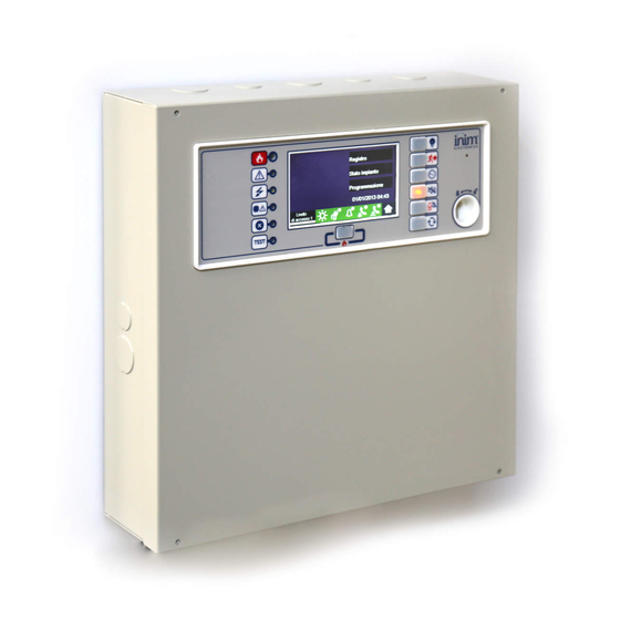
General description Previdia Compact Models Previdia Compact is a series of control panels for the management of fire detection and extinguishing systems. This series provides different models of control panels distinguished by certain technical characteristics such as the number of loops and devices that can be managed, the type of cabinet in which the modules are housed, the presence of signalling LEDs on the frontplate and the possibility of managing an extinction channel. - Page 9 Class 3k5 (EN 60721-3-3). EN54: The gas detection function is not provided for in the aforesaid standard and therefore cannot be considered EN54-2 compliant. Previdia Compact Models Specification PREVIDIA-CxxxS PREVIDIA-CxxxL (in small cabinet)
- Page 10 Fire detection and extinguishant system Touchscreen display Status LED LED and function button LED and multiple-alarm Previdia Compact in large cabinet button Access-key slot Buzzer MicroSD card holder Reset button Button to reset default settings (factory settings) Programming jumper connector...
- Page 11 Installation manual Previdia Compact in small cabinet Back of the motherboard Output connection terminals number name maximum current function 1, 5 500mA Positive Port A (positive and A+, A- 2, 3 negative) Hornet+ network terminal Port B (positive and B+, B-...
-
Page 12: Fire Extinction
5A @ 30V Free voltage relay Fire Extinction Some models of Previdia Compact control panel allow the management of a gas-extinguishing channel. Complies with EN12094-1 and provides the inputs, outputs and control logic required by these systems. Colour On solid... - Page 13 Installation manual Stand-by Manual Blinking Flow switch extinction ACTIVATION from flow sensor Manual Automatic Condition sufficient? Blinking Pre- Extinguishing PRE- Pre-extinguishment time started Stop extinction active Stop extinction Stop extinction MANUAL AUTOMATIC “EXTERNAL” “HOLD” “ADD” “ABORT” Activation Activation Stop extinction Stop active extinction...
- Page 14 Fire detection and extinguishant system The following table contains a description of the functions associated with the extinction that can be programmed for the control panel inputs and outputs (on-board or on loops, through supervised outputs, such as those of the EM312SR modules).
-
Page 15: Previdia-C-Dial, Telephone Line Communicator Module
Previdia-C-DIAL, telephone line Communicator module The optional Previdia-C-DIAL board allows you to connect Previdia Compact control panels to the landline (PSTN) and to the GSM 2G and 3G networks. It manages reporting protocols used by alarm receiving centres. This module allows the control panel to make voice calls and send SMS text messages. -
Page 16: Previdia Compact Rep Repeater
Previdia Compact REP Repeater For installations requiring a system control point other than the point where the Previdia Compact control panel is installed, there are two repeater panel models, that is, devices that allow you to remotely view the information available on the user interface of the control panel. -
Page 17: Control Panels In A Hornet+ Network
(Hornet+ network). Each model of the Previdia Compact control panel provides two RS485 ports for the ring connection (for details on the wiring refer to paragraph 3.7 Connecting the Hornet+ network). -
Page 18: Chapter 3 Installation
Fire detection and extinguishant system Chapter 3 Installation Note: The installation of these control panels must be carried out in full compliance with the local fire regulations, the laws and regulations in force, and in accordance with the instructions and relevant guidelines. -
Page 19: Mounting The Previdia-C-Dial Communicator Module
The ends of wires must not be soft soldered in points where they are subject to clamping. 3.3.1 Mains connection EN54: The power-supply system of Previdia Compact control panels is EN54-4 compliant. Attention: Do not power up the system with a non-compliant voltage. - Page 20 Fire detection and extinguishant system Previdia Compact in small cabinet Note: The end of a stranded wire must not be consolidated with soft soldering in points where the wire is subjected to contact pressure. 2. Crimp the earth line wire to the eyelet terminal [B].
-
Page 21: Connecting The "I/O" Terminals
Installation manual Previdia Compact in large cabinet Previdia Compact in small cabinet Connecting the “I/O” terminals Each of the 4 IN/OUT channels of the control panel (terminals 19-20, 21-22, 23-24, 25-26) can be configured as: • supervised output • input... - Page 22 Fire detection and extinguishant system Connection of polarized devices (sounders, etc.) to channels configured as outputs I/Ox I/Ox 1KOhm - 1W 1KOhm - 1W brown, black, red brown, black, red The polarities refer to the active status of the output, the polarities invert for stand-by status. EN54: If the control panel default settings are left unchanged, the I/O 1 output will result as being configured as a type C output for the connection of audible/visual signalling devices.
-
Page 23: Relay Output Wiring
Installation manual Connection of devices with alarm and fault outputs to channels configured as input The wiring diagram illustrates a connection made to one of I/Ox the “I/O” channels [A], configured as input. The connected device [B] is equipped with a normally closed fault signalling output [C] and a normally open alarm signalling output [D]. -
Page 24: Loop Connections
Fire detection and extinguishant system Loop connections The connection circuits of the peripheral detection/activation devices are defined as “loops”. These loops start from the output terminals, run through the entire protected area connecting in parallel all the system devices before re-entering on the input terminals. -
Page 25: Connecting The Hornet+ Network
Installation manual Connecting the Hornet+ network The connection of two or more control panels (Previdia Max, Previdia Compact or repeaters) in a Hornet+ network can be achieved by using two RS485 communication ports. Cables: 4 wire shielded cable Typical impedance 12Ohm... -
Page 26: Wiring The External Communicators
Fire detection and extinguishant system Wiring the external communicators The Previdia Compact control panels can be used to drive remote alarm or fault signalling devices Cables: 2-wire shielded cable Proper section (minimum 0.5mm², maximum 2.5 mm²) Compliant with local laws and regulations in force The “I/O”... -
Page 27: System Test
Installation manual System test INIM Electronics recommends that the entire system be checked completely at regular intervals. For the instructions for system testing and maintenance refer to the Manual for system configuration, commissioning and maintenance. Replacement and disposal of used devices When replacing obsolete devices, disconnect the devices concerned then complete the connections of the new devices in compliance with the instructions printed on the respective leaflets. - Page 28 Fire detection and extinguishant system ISO 9001 Quality Management certified by BSI with certificate number FM530352 Centobuchi, via Dei Lavoratori 10 63076 Monteprandone (AP) Italy Tel. +39 0735 705007 _ Fax +39 0735 704912 info@inim.biz _ www.inim.biz WEEE DCMIINE0PREVIDIAC-110-20190124...
Need help?
Do you have a question about the PREVIDIA COMPACT and is the answer not in the manual?
Questions and answers