Table of Contents
Advertisement
RRU5909&RRU5309&RRU5309w&RR
U3959a Installation Guide
Contents
7.2.2
RRU5909&RRU5309&RRU5309w&RRU3959a Installation Guide
7.2.2.1
Changes in RRU5909&RRU5309&RRU5309w&RRU3959a Installation Guide
7.2.2.2
7.2.2.2.1
7.2.2.2.2
7.2.2.2.3
7.2.2.3
7.2.2.3.1
7.2.2.3.2
7.2.2.3.3
7.2.2.3.4
7.2.2.3.5
7.2.2.3.5.1
7.2.2.3.5.2
7.2.2.3.5.3
7.2.2.4
7.2.2.5
7.2.2.6
7.2.2.6.1
7.2.2.6.2
7.2.2.6.3
7.2.2.7
7.2.2.7.1
7.2.2.7.2
7.2.2.7.2.1
7.2.2.7.2.2
7.2.2.7.2.3
7.2.2.7.3
7.2.2.7.4
7.2.2.7.5
7.2.2.7.6
7.2.2.8
7.2.2.8.1
7.2.2.8.2
7.2.2.8.3
7.2.2.8.4
7.2.2.8.5
7.2.2.8.6
7.2.2.8.7
7.2.2.8.8
Advertisement
Table of Contents

Subscribe to Our Youtube Channel
Related Manuals for Huawei RRU5909


Summary of Contents for Huawei RRU5909
- Page 1 RRU5909&RRU5309&RRU5309w&RR U3959a Installation Guide Contents 7.2.2 RRU5909&RRU5309&RRU5309w&RRU3959a Installation Guide 7.2.2.1 Changes in RRU5909&RRU5309&RRU5309w&RRU3959a Installation Guide 7.2.2.2 Installation Preparations 7.2.2.2.1 Reference Documents 7.2.2.2.2 Tools and Instruments 7.2.2.2.3 Skills and Requirements for Onsite Personnel 7.2.2.3 Information About the Installation 7.2.2.3.1 RRU Exterior 7.2.2.3.2...
-
Page 2: Installation Guide
This document describes the process of installing blade RRU5909&RRU5309&RRU5309w&RRU3959a(referred to as in this document). RRU is short for remote radio unit. Product Versions The following table lists the product version related to this document for RRU5909&RRU3959a. Product Name Solution Version Product Version • RRU5909&RRU3959a SRAN10.1 and later versions... -
Page 3: Installation Preparations
Powering On an RRU After all the devices are installed, check the power-on status of an RRU. Appendix Huawei Proprietary and Confidential Copyright © Huawei Technologies Co., Ltd. Huawei Proprietary and Confidential Copyright © Huawei Technologies Co., Ltd. Next topic >... - Page 4 This is the ninth official release. Compared with Issue 08 (2018-04-30), this issue does not include any new information. Compared with Issue 08 (2018-04-30), this issue includes the following change. Topic Change Description Modified the figures showing the mounting kits for The whole document an RRU, which have been modified.
- Page 5 Compared with Issue 04 (2017-08-30), this issue does not include any new information. Compared with Issue 04 (2017-08-30), this issue includes the following change. Topic Change Description RRU5909&RRU5309&RRU5309w&RRU3959a Installation Updated the required product versions and added Guide support of the RRU by the DBS5900.
- Page 6 This is a draft. Compared with Draft B (2017-03-10), this issue includes the following change. Topic Change Description RRU5909&RRU5309&RRU5309w&RRU3959a Installation Updated the RRU solution version and product Guide version. Compared with Draft B (2017-03-10), this issue does not include any new information and no information is deleted from this issue.
-
Page 7: Tools And Instruments
Compared with Draft A (2017-01-20), this issue does not include any new information and no information is deleted from this issue. Draft A (2017-01-20) This is a draft. Huawei Proprietary and Confidential Copyright © Huawei Technologies Co., Ltd. Huawei Proprietary and Confidential Copyright © Huawei Technologies Co., Ltd. Next topic >... - Page 8 Huawei Proprietary and Confidential Copyright © Huawei Technologies Co., Ltd. Next topic > 7.2.2.2.2 Tools and Instruments This section describes the tools and instruments that must be prepared before the remote radio unit (RRU) installation. Hammer drill (φ 12 bit, a φ 14 bit)
- Page 9 Before the installation, pay attention to the following items: • The customer's technical engineers must be trained by Huawei and be familiar with the proper installation and operation methods. •...
-
Page 10: Information About The Installation
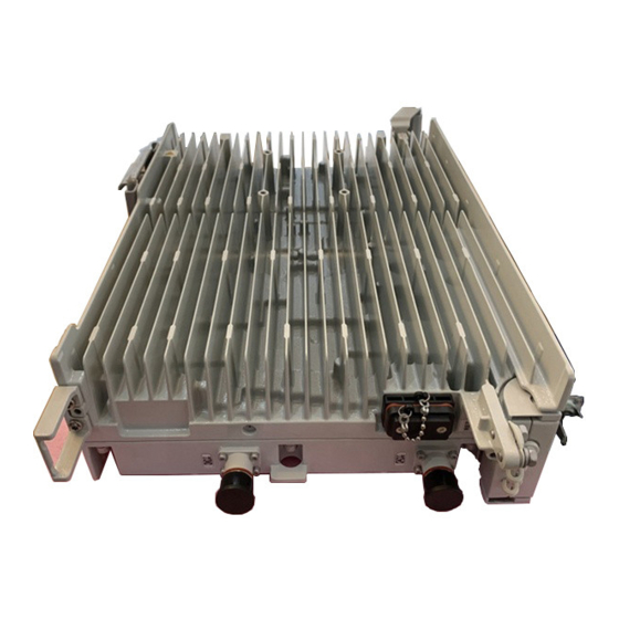
Parent Topic: Installation Preparations Huawei Proprietary and Confidential Copyright © Huawei Technologies Co., Ltd. Huawei Proprietary and Confidential Copyright © Huawei Technologies Co., Ltd. < Previous topic 7.2.2.3 Information About the Installation Before installing an RRU, you must be familiar with its exterior, ports, indicators, installation scenarios, and installation clearance requirements. - Page 11 Figure 1 RRU exterior shows RRU dimensions. Figure 2 Figure 2 RRU dimensions You can obtain the RRU name, RRU frequency band and power supply information from the nameplate on the cover plate. shows the positions of the nameplate on the RRU. Figure 3 NOTE: The actual nameplate may differ from what is shown in the figure.
- Page 12 (2) Module name (3) Frequency band (4) Power supply type Parent Topic: RRU Introduction Huawei Proprietary and Confidential Copyright © Huawei Technologies Co., Ltd. Huawei Proprietary and Confidential Copyright © Huawei Technologies Co., Ltd. Next topic > 7.2.2.3.2 RRU Ports This section describes ports on the panels.
- Page 13 Figure 1 Ports on the RRU panels Table 1 Ports and indicators on the RRU panels Item Silkscreen Remarks (1) Ports in the cabling RTN(+) Power supply socket, For details about RRU power cavity cable appearance and specifications, see RRU Power NEG(-) Cable Optical/electrical port 0, connected to the...
- Page 14 Connect the CPRI0 port to the BBU by default in the single-mode scenario. Parent Topic: RRU Introduction Huawei Proprietary and Confidential Copyright © Huawei Technologies Co., Ltd. Huawei Proprietary and Confidential Copyright © Huawei Technologies Co., Ltd. < Previous topic Next topic >...
- Page 15 Table 1 RRU Indicators Indicator Color Status Meaning Blinking (on for The board software is being loaded, or the board is 0.125s and off for not working. 0.125s) Steady on Alarms are generated, and the module must be replaced. Blinking (on for 1s Alarms are generated.
- Page 16 Steady on: VSWR alarms are generated on one or more ports. Parent Topic: RRU Introduction Huawei Proprietary and Confidential Copyright © Huawei Technologies Co., Ltd. Huawei Proprietary and Confidential Copyright © Huawei Technologies Co., Ltd. < Previous topic Next topic >...
- Page 17 RRU is a professional communications equipment and cannot be installed in areas which are accessible to people. The installation scenarios involve the related security features. For details about specific requirements and precautions, see Safety Information. Application scenarios: To ensure proper heat dissipation of the RRU, the following requirements must be met: •...
- Page 18 RRU stacked installation. When the horizontal distance between the main and auxiliary poles on a tower is greater than or equal to 810 mm (23.62 in.), the side-mounted mode is recommended for installing RRUs on the auxiliary pole to meet the minimum clearance requirements. Otherwise, the standard mode is recommended for installing RRUs on the auxiliary pole.
- Page 19 NOTICE: • The diameter of a pole for installing an RRU ranges from 60 mm (2.36 in.) to 114 mm (4.49 in.). The recommended diameter is 80 mm (3.15 in.). • The recommended thickness of the pole wall is 3.5 mm (0.14 in.) or above. •...
- Page 20 Figure 5 Two RRUs installed on a pole , and show multiple RRUs installed on a pole. Figure 6 Figure 7 Figure 8 Figure 6 Three RRUs installed on an IFS06...
- Page 21 Figure 7 Four RRUs installed on a pole Figure 8 Six RRUs installed on an IFS06 Installing an RRU on U-Steel shows U-steel specifications. Figure 9 Figure 9 U-steel specifications...
- Page 22 NOTICE: U-steel supports only the standard or reverse installation of a single RRU. shows an RRU installed on U-steel. Figure 10 Figure 10 RRU installed on U-steel Installing an RRU on Angle Steel shows angle steel specifications. Figure 11 Figure 11 Angle steel specifications...
- Page 23 NOTICE: Angle steel supports only the standard or reverse installation of a single RRU. shows an RRU installed on angle steel. Figure 12 Figure 12 RRU installed on angle steel Installing an RRU on a Wall The wall for installing RRUs must meet the following requirements: •...
- Page 24 Figure 13 Correct installation of RRUs installed on a wall in side-mounted mode shows an RRU installed on a wall. Figure 14 Figure 14 RRU installed on a wall Installing an RRU on an IFS06 • The upper and lower adjustable beams on an IFS06 can be moved up and down to fit for heights of RRUs.
- Page 25 NOTICE: RRUs cannot be stacked when the RRUs are installed on an IFS06, as shown in Figure 15 Figure 15 Correct installation of RRUs installed on an IFS06 show RRUs installed on an IFS06. Figure 16 Figure 17...
- Page 26 Figure 16 Three RRUs installed on an IFS06 (1) Height-restricted scenario (2) Height-unrestricted scenario...
- Page 27 (1) Height-restricted scenario (2) Height-unrestricted scenario Parent Topic: Information About the Installation Huawei Proprietary and Confidential Copyright © Huawei Technologies Co., Ltd. Huawei Proprietary and Confidential Copyright © Huawei Technologies Co., Ltd. < Previous topic Next topic > 7.2.2.3.5 Installation Clearance Requirements...
-
Page 28: Clearance For A Single Rru
Installation Spacing Between RRUs This section describes the horizontal and vertical spacing between RRUs. Parent Topic: Information About the Installation Huawei Proprietary and Confidential Copyright © Huawei Technologies Co., Ltd. Huawei Proprietary and Confidential Copyright © Huawei Technologies Co., Ltd. < Previous topic 7.2.2.3.5.1 Clearance for a Single RRU... - Page 29 Figure 1 Clearance for a single RRU in side-mounted mode Clearance for a Single RRU in Standard or Reverse Mode shows the clearance for a single RRU in standard or reverse mode. Figure 2...
- Page 30 Figure 2 Clearance for a single RRU in standard or reverse mode Clearance for a Single Tower-Mounted RRU show the minimum clearances for a single RRU in side-mounted mode and Figure 3 Figure 4 standard or reverse mode on a tower.
- Page 31 Figure 4 Minimum clearance for a single RRU in standard or reverse mode on a tower Parent Topic: Installation Clearance Requirements of an RRU Huawei Proprietary and Confidential Copyright © Huawei Technologies Co., Ltd. Huawei Proprietary and Confidential Copyright © Huawei Technologies Co., Ltd.
- Page 32 This section describes the recommended and minimum clearances for three or more RRUs. NOTICE: If an is installed on the bitumen ground, the RRU must be at least 500 mm (700 mm or more is recommended) away from the bitumen ground. The following describes the space requirements for installing multiple RRUs on the non-bitumen ground.
- Page 33 Minimum Clearances for Multiple RRUs Installed in Stacked Mode shows the minimum clearances for multiple RRUs installed in stacked mode. Figure 2 Figure 2 Minimum clearances for multiple RRUs installed in stacked mode Recommended Clearances for Multiple RRUs Installed in Standard or Reverse Mode on a Wall shows the recommended clearances for multiple RRUs installed in standard or reverse mode Figure 3...
- Page 34 Figure 3 Recommended clearances for multiple RRUs installed in standard or reverse mode on a wall Minimum Clearances for Multiple RRUs Installed in Standard or Reverse Mode on a Wall shows the minimum clearances for multiple RRUs installed in standard or reverse mode on a Figure 4 wall.
- Page 35 Figure 5 Recommended clearances for multiple RRUs installed in side-mounted mode on a wall Parent Topic: Installation Clearance Requirements of an RRU Huawei Proprietary and Confidential Copyright © Huawei Technologies Co., Ltd. Huawei Proprietary and Confidential Copyright © Huawei Technologies Co., Ltd.
- Page 36 Minimum Horizontal Spacing Between RRUs shows the minimum horizontal spacing between RRUs. Figure 2 Figure 2 Minimum horizontal spacing between RRUs Recommended Vertical Spacing Between RRUs shows the recommended vertical spacing between RRUs. Figure 3 Figure 3 Recommended vertical spacing between RRUs...
- Page 37 Minimum Vertical Spacing Between RRUs shows the minimum vertical spacing between RRUs. Figure 4 Figure 4 Minimum vertical spacing between RRUs...
-
Page 38: Unpacking The Equipment
Parent Topic: Installation Clearance Requirements of an RRU Huawei Proprietary and Confidential Copyright © Huawei Technologies Co., Ltd. Huawei Proprietary and Confidential Copyright © Huawei Technologies Co., Ltd. < Previous topic 7.2.2.4 Unpacking the Equipment This chapter describes how to unpack and check the delivered equipment to ensure that all the materials are included and intact. - Page 39 The outer packing is intact Go to The outer packing is severely damaged or soaked Find out the cause and report it to the local Huawei office. 3. Check the type and quantity of the equipment in the cases according to the packing list.
-
Page 40: Installation Process
Huawei Proprietary and Confidential Copyright © Huawei Technologies Co., Ltd. Huawei Proprietary and Confidential Copyright © Huawei Technologies Co., Ltd. < Previous topic Next topic > 7.2.2.5 Installation Process The installation process involves installing an and RRU cables, checking the RRU hardware installation, and powering on an RRU. -
Page 41: Hoisting Optical Fibers Onto A Tower
Hoisting Power Cables onto a Tower This section describes the procedure for hoisting power cables onto a tower and the precautions that must be taken. Huawei Proprietary and Confidential Copyright © Huawei Technologies Co., Ltd. Huawei Proprietary and Confidential Copyright © Huawei Technologies Co., Ltd. - Page 42 Figure 1 Binding mounting kits for the RRU (1) Lifting sling (2) Traction sling 3. Installation engineer A catches the mounting kits and then unties the slings. 4. Install the mounting kits. For detailed operations, see steps 1 to 3 in Installing a Single RRU 5.
- Page 43 (1) Handle (2) Lifting sling (3) Traction eye (4) Traction sling Figure 3 Incorrect binding method (1) Figure 4 Incorrect binding method (2) 6. Hoist the RRU onto the tower, as shown in . Installation engineer B pulls the lifting sling Figure 5 downwards, and installation engineer C pulls the traction sling outwards to protect the RRU from colliding with the tower.
- Page 44 NOTE: The procedure for hoisting the RRU and its mounting kits onto the tower is for your reference only. Parent Topic: Hoisting an RRU and Related Cables onto a Tower Huawei Proprietary and Confidential Copyright © Huawei Technologies Co., Ltd.
- Page 45 Huawei Proprietary and Confidential Copyright © Huawei Technologies Co., Ltd. Next topic > 7.2.2.6.2 Hoisting Optical Fibers onto a Tower This section describes the procedure for hoisting optical fibers onto a tower and the precautions that must be taken. Context Cabling requirements for power cables are met.
- Page 46 a. After climbing up to the tower, installation engineer A secures the fixed pulley to the tower platform support and leads the lifting sling through the fixed pulley. b. Installation engineer B places the fiber coiler for coiling optical fibers on the fiber spools, and installation engineer D lead the lifting sling through the stretch sling of the optical fibers and use the other sling as a traction sling to secure the cables 4 m (13.12 ft) away from the lifting sling, as shown in...
- Page 47 The procedure for hoisting the optical fibers onto the tower is for your reference only. Parent Topic: Hoisting an RRU and Related Cables onto a Tower Huawei Proprietary and Confidential Copyright © Huawei Technologies Co., Ltd. Huawei Proprietary and Confidential Copyright © Huawei Technologies Co., Ltd.
- Page 48 Figure 1 Hoisting power cables onto the tower (1) Lifting sling (2) Fixed pulley (2) power cables a. After climbing up to the tower, installation engineer A secures the fixed pulley to the tower platform support and leads the lifting sling through the fixed pulley. b.
- Page 49 Figure 2 Binding cable ties c. Installation engineer B wraps the power cable connector with a layer of PVC insulation tape, as shown in Figure 3 NOTE: Wrap the PVC insulation tape from 30 mm (1.18 in.) away from one end of the connector until it reaches the other end of the connector.
-
Page 50: Installing The Rru
The procedure for hoisting the power cables onto the tower is for your reference only. Parent Topic: Hoisting an RRU and Related Cables onto a Tower Huawei Proprietary and Confidential Copyright © Huawei Technologies Co., Ltd. Huawei Proprietary and Confidential Copyright © Huawei Technologies Co., Ltd. - Page 51 Installing an RRU on an IFS06 This section describes the process and precautions for installing an RRU on an IFS06. Huawei Proprietary and Confidential Copyright © Huawei Technologies Co., Ltd. Huawei Proprietary and Confidential Copyright © Huawei Technologies Co., Ltd.
-
Page 52: Installing A Single Rru
Parent Topic: Installing the RRU Huawei Proprietary and Confidential Copyright © Huawei Technologies Co., Ltd. Huawei Proprietary and Confidential Copyright © Huawei Technologies Co., Ltd. Next topic > 7.2.2.7.2 Installing the RRU on a Pole One or more RRUs can be installed on a pole. - Page 53 7.2.2.7.2.1 Installing a Single RRU This section describes the procedure and precautions for installing a single on a pole. Prerequisites • Before you install an RRU on a pole secured on a tower, the RRU and its mounting kits are hoisted onto the tower.
- Page 54 2. Install the RRU mounting kits, as shown in Figure 2 Figure 2 Installing the RRU mounting kits NOTE: Ensure that the arrows on the mounting kits are pointing up. Adjust the position of the nut and remove the square-neck bolt at the open end from the slot on the auxiliary bracket.
- Page 55 Figure 3 Securing the RRU mounting kits 4. Install the RRU onto the main bracket, as shown in Figure 4 Figure 4 Installing the RRU onto the main bracket 5. Use an inner hexagon torque screwdriver to tighten the captive screw into the holes on the top of the attachment plate and main bracket to 5 N·m (44.25 lbf·in.) so that the attachment plate and main bracket are firmly secured, as shown in Figure 5...
- Page 56 Figure 5 Securing the captive screw into the connection hole Parent Topic: Installing the RRU on a Pole Huawei Proprietary and Confidential Copyright © Huawei Technologies Co., Ltd. Huawei Proprietary and Confidential Copyright © Huawei Technologies Co., Ltd. Next topic >...
- Page 57 Figure 1 Installing the first RRU onto the main bracket 2. Use an M6 inner hexagon screwdriver to loosen the four hex socket screws from the main bracket and pole mounting kit on the second set of mounting kits, and remove the main bracket, as shown in Figure 2 Figure 2 Removing the RRU main bracket...
- Page 58 Figure 3 Installing the second main bracket (1) Removed main bracket NOTE: The main mounting bracket for installing a blade RRU can connect to the main mounting bracket for installing a common RRU in the scenarios of adding RRUs, as shown in Figure 4 Figure 4 Connecting to the main mounting bracket for installing a common RRU (1) Main mounting bracket for a blade RRU...
- Page 59 Figure 5 Installing the second RRU onto the main bracket NOTICE: After installing each RRU on its main bracket, use an inner hexagon torque screwdriver to tighten the captive screw into the holes on the top of the attachment plate and main bracket to 5 N·m (44.25 lbf·in.) so that the attachment plate and main bracket are firmly secured, as shown Figure 6 Figure 6 Securing the captive screw into the connection hole...
- Page 60 5 N·m (44.25 lbf·in.). Parent Topic: Installing the RRU on a Pole Huawei Proprietary and Confidential Copyright © Huawei Technologies Co., Ltd. Huawei Proprietary and Confidential Copyright © Huawei Technologies Co., Ltd. < Previous topic Next topic >...
- Page 61 Context A pole supports three, four, or six RRUs. The procedures for installing them are the same. The following provides an example for the procedure of installing four RRUs on a pole. NOTICE: RRUs can be stacked only when installed on one or more poles, and a maximum of three RRUs can be stacked.
- Page 62 Figure 2 Removing the RRU main bracket (1) Main bracket (2) Pole mounting kit 3. Install the third main bracket and install the third RRU onto the third main bracket. Then, use an inner hexagon torque screwdriver to tighten the captive screw into the holes on the top of the attachment plate and main bracket for the RRU to 5 N·m (44.25 lbf·in.), as shown in Figure 3 NOTICE:...
- Page 63 The main mounting bracket for installing a blade RRU can connect to the main mounting bracket for installing a common RRU in the scenarios of adding RRUs, as shown in Figure 4 Figure 4 Connecting to the main mounting bracket for installing a common RRU (1) Main mounting bracket for a blade RRU (2) Main mounting bracket for a common RRU 4.
- Page 64 5 N·m (44.25 lbf·in.) so that the attachment plate and main bracket are firmly secured, as shown in Figure 7 Figure 7 Installing the fourth RRU onto the fourth main bracket Parent Topic: Installing the RRU on a Pole Huawei Proprietary and Confidential Copyright © Huawei Technologies Co., Ltd.
-
Page 65: Installing An Rru On U-Steel
Huawei Proprietary and Confidential Copyright © Huawei Technologies Co., Ltd. < Previous topic 7.2.2.7.3 Installing an RRU on U-steel This section describes the procedure and precautions for installing an on U-steel. An RRU can be installed on U-steel secured on the ground or a tower. Each piece of U-steel allows only one RRU to be installed in standard or reverse mode. - Page 66 Figure 1 Top view of an RRU (1) U-steel Procedure 1. Determine a position for installing the mounting kits. • If the RRU is installed on a tower, determine a position for installing the mounting kits according to the instructions in Clearance for a Single RRU •...
- Page 67 NOTE: As shown in the figure above, it is recommended that the mounting kits be installed at a position 1200 mm (47.24 in.) to 1600 mm (59.06 in.) high above the ground. If the space is insufficient, only the Installation Clearance Requirements of an RRU needs to be provided.
- Page 68 Figure 4 Securing the RRU mounting kits 4. Use an inner hexagon torque screwdriver to remove the attachment plate from one side of the RRU, reinstall the attachment plate onto the rear of the RRU, and tighten the four stainless screws to 5 N·m (44.25 lbf·in.), as shown in Figure 5 Figure 5 Installing the attachment plate onto the rear of the RRU...
- Page 69 Figure 7 Securing the captive screw into the connection hole Parent Topic: Installing the RRU Huawei Proprietary and Confidential Copyright © Huawei Technologies Co., Ltd. Huawei Proprietary and Confidential Copyright © Huawei Technologies Co., Ltd. < Previous topic Next topic >...
-
Page 70: Installing An Rru On Angle Steel
7.2.2.7.4 Installing an RRU on Angle Steel This section describes the process and precautions for installing an on angle steel. An RRU can be installed on angle steel secured on the ground or a tower. Each piece of angle steel allows only one RRU to be installed in standard or reverse mode. - Page 71 Figure 2 Distance between the mounting kits and the ground NOTE: As shown in the figure above, it is recommended that the mounting kits be installed at a position 1200 mm (47.24 in.) to 1600 mm (59.06 in.) high above the ground. If the space is insufficient, only the Installation needs to be provided.
- Page 72 3. Use a 16 mm (0.63 in.) M10 torque wrench to tighten the nuts to 40 N·m so that the mounting kits are secured onto the angle steel, as shown in Figure 4 NOTICE: Tighten the nuts on the two square-neck bolts simultaneously. After the main and auxiliary brackets are secured properly, measure the spacing between the mounting kits on both sides and ensure that the spacing is the same on the two sides.
- Page 73 Figure 7 Securing the captive screw into the connection hole Parent Topic: Installing the RRU Huawei Proprietary and Confidential Copyright © Huawei Technologies Co., Ltd. Huawei Proprietary and Confidential Copyright © Huawei Technologies Co., Ltd. < Previous topic Next topic >...
-
Page 74: Installing An Rru On A Wall
7.2.2.7.5 Installing an RRU on a Wall This section describes the procedure and precautions for installing an on a wall. Prerequisites The hoist clamp on the main bracket is secured properly. NOTICE: • Do not stand an RRU upright because the ports cannot support the weight of the RRU. - Page 75 (5) Flat washer (6) Spring washer (7) Nut (8) Plastic screw cap a. Use an M6 inner hexagon torque screwdriver to remove the four inner hexagon screws on the pole installation bracket, and remove the main bracket from the pole installation bracket. b.
- Page 76 Figure 3 Drilling holes and inserting expansion anchor bolts (1) M10x80 bolt (2) Nut (3) Spring washer (4) Flat washer (5) Expansion sleeve a. Use a hammer drill with a Ф12 bit to drill holes vertically at the marked anchor points with the depth ranging from 55 mm (2.17 in.) to 60 mm (2.36 in.), and use a vacuum cleaner to clear the dust out from inside and around the holes, and measure the distances between holes.
- Page 77 Figure 4 Installing the pole installation bracket on the expansion anchor bolts NOTICE: Ensure that the arrows on the pole installation bracket are pointing up. 5. Install the main bracket onto the pole installation bracket using four M6x16 inner hexagon screws, and use an inner hexagon torque screwdriver to tighten the inner hexagon screws to 5 N·m (44.25 lbf·in.) so that the main bracket and pole installation bracket are firmly secured, as shown in...
- Page 78 (1) Main bracket (2) Pole installation bracket 6. Use an inner hexagon torque screwdriver to remove the attachment plate from one side of the RRU, reinstall the attachment plate onto the rear of the RRU, and tighten the four stainless screws to 5 N·m (44.25 lbf·in.), as shown in Figure 6 Figure 6 Installing the attachment plate onto the rear of the RRU...
- Page 79 Figure 8 Securing the captive screw into the connection hole Parent Topic: Installing the RRU Huawei Proprietary and Confidential Copyright © Huawei Technologies Co., Ltd. Huawei Proprietary and Confidential Copyright © Huawei Technologies Co., Ltd. < Previous topic Next topic >...
- Page 80 lowest operating temperature of the RRUs and at least 10°C (50°F) lower than the highest operating temperature of the RRUs. NOTE: For details about the operating temperature of the RRUs, see section "Technical Specifications of RRUs" in Base Station Technical Description. •...
- Page 81 2. Install the RRU main bracket using the M10x50 bolts delivered with the IFS06. Then tighten the bolts using an M10 torque socket to 30 N·m (265.52 lbf·in.). NOTICE: Ensure that the arrows on the pole mounting kits are pointing up. Install the RRU mounting kits, as shown in Figure 2 Figure 2 Installing the pole mounting kit in height-unrestricted scenario...
- Page 82 Figure 3 Installing the RRU main brackets (1) Main bracket (2) Pole mounting kit 4. Attach the RRU to the main bracket, and then use an inner hexagon screwdriver to tighten the captive screw into the holes of the attachment plate and main bracket to 5 N·m (44.25 lbf·in.) so that the attachment plate and main bracket are firmly secured, as shown in Figure 4...
- Page 83 Figure 4 Installing and securing the RRU on the main bracket 5. Install the RRUs on the lower level from left to right, as shown in Figure 5...
- Page 84 Figure 5 Installing RRUs on the lower level 6. Optional: When the ambient temperature is greater than or equal to the lowest operating temperature of the RRU and at least 10°C (50°F) lower than the highest operating temperature of the RRU, repeat the preceding steps to install the RRUs on the higher level, as shown in Figure 6...
-
Page 85: Installing Rru Cables
Figure 6 Installing RRUs on the higher level Parent Topic: Installing the RRU Huawei Proprietary and Confidential Copyright © Huawei Technologies Co., Ltd. Huawei Proprietary and Confidential Copyright © Huawei Technologies Co., Ltd. < Previous topic 7.2.2.8 Installing RRU Cables This chapter describes the procedure for installing cables. -
Page 86: Rru Cable List
Closing the Cover Plate of an RRU Cabling Cavity This section describes the procedure for closing the cover plate of an RRU cabling cavity. Huawei Proprietary and Confidential Copyright © Huawei Technologies Co., Ltd. Huawei Proprietary and Confidential Copyright © Huawei Technologies Co., Ltd. - Page 87 • The bending radius of a fiber optic cable is at least 20 times of its diameter, and the bending radius of a breakout cable is at least 30 mm (1.18 in.). • The bending radius of an E1/T1 cable must be at least three times its diameter. •...
- Page 88 • When routing cables through tubes on the ground below the cabinet, put a 30 mm to 50 mm (1.18 in. to 1.97 in.) length of the tubes into the base of the cabinet but do not put the tubes into the cabinet.
- Page 89 Figure 2 Cables secured on a cable tray (1) 3-hole clip (2) 6-hole clip The following figure shows the cables secured on a tower.
- Page 90 Figure 3 Cables secured on a tower (1) 3-hole clip (2) 6-hole clip Special Cabling Requirements Cabling of power cables • Power cables must be installed in the position specified in engineering design documents. • If the length of power cables is insufficient, replace the cables rather than adding connectors or soldering joints to lengthen the cables.
- Page 91 • After routing a DC power cable close to the equipment on a tower, use clips to secure the power cable onto a pole or the rails surrounding the platform. Ensure that there is no excessively long distance between the equipment and the position where the power cable is secured. Cabling of PGND cables •...
- Page 92 • The operating temperature of fiber optic cables ranges from -40ºC to +60ºC (-40ºF to +140ºF). If the actual temperature is beyond this range, take protective measures or select another route. • Do not circle and twist cables. • Do not bind a fiber optic cable at the position where it bends. •...
- Page 93 Coil the excess of the fiber optic cables near the equipment on the tower before securing the cables on the tower. Parent Topic: Installing Cables Huawei Proprietary and Confidential Copyright © Huawei Technologies Co., Ltd. Huawei Proprietary and Confidential Copyright © Huawei Technologies Co., Ltd. Next topic >...
- Page 94 show the cable connections of a single-mode RRU. Figure 1 Figure 2 NOTE: When the following scenarios need to be monitored by RRUs, • If the external power supply system needs to be monitored and supports modulating RS485 and dry contact alarm signals using power cables, you do not need to install the MEB.
- Page 95 Figure 2 Cable connections of a single-mode RRU (MEB installed) (1) RRU PGND cable (2) RRU RF jumper (3) RRU AISG multi-wire cable (4) RRU AISG extension cable (5) RRU power cable (6) CPRI optical fiber (7) MEB power cable (8) MEB alarm cable shows the cable connections of a multimode RRU.
- Page 96 Figure 3 Cable connections of a multimode RRU (1) RRU PGND cable (2) RRU RF jumper (3) RRU AISG multi-wire cable (4) RRU AISG extension cable (5) RRU power cable (6) CPRI optical fiber shows the cable connections of multiple single-mode RRUs. Figure 4...
- Page 97 (3) RRU power cable (4) CPRI optical fiber Parent Topic: Installing RRU Cables Huawei Proprietary and Confidential Copyright © Huawei Technologies Co., Ltd. Huawei Proprietary and Confidential Copyright © Huawei Technologies Co., Ltd. < Previous topic Next topic > 7.2.2.8.3 Installing RRU Cables This chapter describes the procedure for installing cables.
- Page 98 Figure 1 Procedure for installing RRU cables Parent Topic: Installing RRU Cables Huawei Proprietary and Confidential Copyright © Huawei Technologies Co., Ltd. Huawei Proprietary and Confidential Copyright © Huawei Technologies Co., Ltd. < Previous topic Next topic > 7.2.2.8.4 RRU Cable List This section describes cable connections.
- Page 99 RRU AISG Extension Standard AISG Standard AISG Standard AISG Standard AISG Cable female connector male connector on male connector female connector on the AISG the RCU multi-wire cable Parent Topic: RRU Cables Huawei Proprietary and Confidential Copyright © Huawei Technologies Co., Ltd.
- Page 100 Huawei Proprietary and Confidential Copyright © Huawei Technologies Co., Ltd. Next topic > 7.2.2.8.5 Installing an RRU PGND Cable This section describes the procedure for installing an PGND cable. Context The cross-sectional area of an RRU PGND cable is 16 mm (0.025 in.
- Page 101 3. Label the installed cables according to the instructions in Attaching a Cable-Tying Label Parent Topic: Installing RRU Cables Huawei Proprietary and Confidential Copyright © Huawei Technologies Co., Ltd. Huawei Proprietary and Confidential Copyright © Huawei Technologies Co., Ltd. < Previous topic Next topic >...
- Page 102 Figure 1 Installing an RRU RF jumper NOTICE: On AC-powered electric railways, such as high-speed railways, when leaky cables are connected to RRUs installed in tunnels, high-voltage-resistance blocks must be installed between RRU RF jumpers and the leaky cables to protect the RRUs against damage. 2.
- Page 103 Figure 2 Waterproofing a connector of the RF jumper (1) Waterproof tape (2) PVC insulation tape NOTE: • Before wrapping waterproof tape, stretch the tape evenly until the length of the tape becomes twice its original length. • Do not stretch the PVC insulation tape when wrapping the PVC insulation tape. •...
- Page 104 7. Attach color-coding to the installed RF jumper according to the instructions in Attaching the Color Ring Parent Topic: Installing RRU Cables Huawei Proprietary and Confidential Copyright © Huawei Technologies Co., Ltd. Huawei Proprietary and Confidential Copyright © Huawei Technologies Co., Ltd. < Previous topic Next topic >...
- Page 105 7.2.2.8.7 Installing an RRU AISG Multi-Wire Cable and AISG Extension Cable This section describes the procedures for installing an RRU AISG multi-wire cable and AISG extension cable. Context When the distance between an RRU and a Remote Control Unit (RCU) is longer than 5 m (16.4 ft.), an AISG multi-wire cable is not long enough to connect the RRU and the RCU.
- Page 106 6. Label the installed cables according to the instructions in Attaching an L-Shaped Label • Install an AISG multi-wire cable that is configured with an AISG extension cable. 1. Use an M3 flat-head screwdriver to loosen the screws on the dustproof cap on the RET port and remove the dustproof cap.
- Page 107 Figure 3 Installing an RRU AISG extension cable 5. Waterproof the joint of the AISG multi-wire cable and AISG extension cable. NOTE: ▪ Before wrapping waterproof tape, stretch the tape evenly until the length of the tape becomes twice its original length.
- Page 108 7. Label the installed cables according to the instructions in Attaching an L-Shaped Label Parent Topic: Installing RRU Cables Huawei Proprietary and Confidential Copyright © Huawei Technologies Co., Ltd. Huawei Proprietary and Confidential Copyright © Huawei Technologies Co., Ltd. < Previous topic Next topic >...
- Page 109 2. Use an M4 Phillips screwdriver to rotate the locking screw on the cover plate of the cabling cavity 90 degrees counterclockwise to unlock the cover plate. Then, pull the handle outwards to open the RRU cabling cavity, as shown in Figure 1 NOTICE: Do not use the electric screwdriver to rotate the locking screw.
- Page 110 Remove only the waterproof blocks for the cables to be installed. Parent Topic: Installing RRU Cables Huawei Proprietary and Confidential Copyright © Huawei Technologies Co., Ltd. Huawei Proprietary and Confidential Copyright © Huawei Technologies Co., Ltd. < Previous topic Next topic >...
- Page 111 • SM and MM labels on an optical module: SM indicates a single-mode optical module, and MM indicates a multimode optical module. • Color of the puller on an optical module: Blue indicates a single-mode optical module, and black or gray indicates a multimode optical module. NOTICE: The optical modules to be installed must match CPRI rates.
- Page 112 • To avoid any damage to optical fibers, the fibers connected to the RRU must be installed according to the installation process. For details about the installation process, see Installing RRU Cables • When installing CPRI optical fibers for dual-fiber bidirectional optical modules, remove the dustproof caps from the ports on the optical module and those from the optical fiber connector, and connect the end labeled 1A and 1B on the optical fiber to the optical modules on the RRU side, as shown in...
- Page 113 4. Label the installed fibers according to the instructions in Attaching an L-Shaped Label Parent Topic: Installing RRU Cables Huawei Proprietary and Confidential Copyright © Huawei Technologies Co., Ltd. Huawei Proprietary and Confidential Copyright © Huawei Technologies Co., Ltd. < Previous topic Next topic >...
- Page 114 Table 1 RRU power cables Cable On the RRU Side On the Power Power Color Device Side Device Female fast Female fast A cable with a black jacket and two wires power connector (pressfit connector inside DCDU- cable type) (pressfit type) •...
- Page 115 4. Label the installed fibers according to the instructions in Attaching a Cable-Tying Label Parent Topic: Installing RRU Cables Huawei Proprietary and Confidential Copyright © Huawei Technologies Co., Ltd. Huawei Proprietary and Confidential Copyright © Huawei Technologies Co., Ltd. < Previous topic Next topic >...
- Page 116 This section describes the procedure for closing the cover plate of an cabling cavity. Procedure 1. Fasten the cables using clips, as shown in Figure 1 NOTICE: Ensure that the exposed shield layer of the power cable is properly tightened using the clip. Figure 1 Fastening cables using clips 2.
- Page 117 Figure 2 Correct placement of waterproof blocks 3. Push the handle to close the cover plate of the cabling cavity. Then, use an M4 Phillips screwdriver to rotate the locking screw on the cover plate of the cabling cavity 90 degrees clockwise shown in the following figure to lock the cover plate of the cabling cavity, as shown Figure 3 NOTICE:...
- Page 118 4. Take off the ESD gloves, and pack up all the tools. Parent Topic: Installing RRU Cables Huawei Proprietary and Confidential Copyright © Huawei Technologies Co., Ltd. Huawei Proprietary and Confidential Copyright © Huawei Technologies Co., Ltd. < Previous topic 7.2.2.9 Checking the RRU Hardware...
- Page 119 Labels are correct, legible, and complete at both ends of each cable, feeder, and jumper. All ground cables are properly grounded. Huawei Proprietary and Confidential Copyright © Huawei Technologies Co., Ltd. Huawei Proprietary and Confidential Copyright © Huawei Technologies Co., Ltd.
- Page 120 -36 V DC to -57 V DC. (b) The RUN indicator on the RRU is on for 1s and off for 1s. The ALM indicator is steady off. Huawei Proprietary and Confidential Copyright © Huawei Technologies Co., Ltd. Huawei Proprietary and Confidential Copyright ©...
- Page 121 7.2.2.11.1 Adding a Female Fast Connector(Pressfit Type) to the RRU Power Cable on the RRU Side This section describes the procedure for adding a female fast connector(Pressfit Type) to the power cable on the RRU side. Context shows the cable diagram on labels. Figure 1 Figure 1 Cable diagram on labels (1) Cable diagram on labels...
- Page 122 2. Strip the specified length of the sheath off the power cable, as shown in Figure 3 Figure 3 Stripping the specified length of sheath 3. Strip a specified length of sheath off each core wire. The length must be consistent with the length of the notch in the female fast connector(Pressfit Type), as shown in Figure 4 Figure 4 Stripping the sheath off each core wire...
- Page 123 b. Connect the blue core wire labeled NEG(-) to the - port and the black/red/brown core wire labeled RTN(+) to the + port on the female fast connector (pressfit type), and then tighten the screws using a Phillips screwdriver to 1.4 N·m (12.39 lbf·in.), as shown in Figure 7 DANGER: Do not reversely connect the positive and negative poles.
- Page 124 Figure 8 Stripping the sheath off the power cable NOTICE: Each core wire is exposed outside the female fast connector (pressfit type) for 1.5 mm (0.059 in.), as shown in Figure 9 Figure 9 Inserting core wires into the female fast connector (pressfit type) Exception Handling If the power terminal or cable is damaged or abnormal, remove the power cable.
- Page 125 Figure 10 Pressing the spring clip of the power terminal Parent Topic: Appendix Huawei Proprietary and Confidential Copyright © Huawei Technologies Co., Ltd. Huawei Proprietary and Confidential Copyright © Huawei Technologies Co., Ltd.
Need help?
Do you have a question about the RRU5909 and is the answer not in the manual?
Questions and answers