Lightware MX9x9DVI-Plus User Manual
Multimedia matrix switcher
Hide thumbs
Also See for MX9x9DVI-Plus:
- User manual (89 pages) ,
- Quick start manual (2 pages) ,
- Quick start manual (2 pages)

Subscribe to Our Youtube Channel
Related Manuals for Lightware MX9x9DVI-Plus


Summary of Contents for Lightware MX9x9DVI-Plus
- Page 1 User’s Manual MX9x9DVI-Plus MX12x12DVI-Plus MX16x16DVI-Plus Multimedia Matrix Switcher...
-
Page 2: Important Safety Instructions
MX DVI-Plus Series – User's Manual Important Safety Instructions Waste Electrical & Electronic Equipment Common Safety Symbols WEEE Class I apparatus construction. Symbol Description This marking shown on the product or its literature, This equipment must be used with a mains power system with a indicates that it should not be disposed with other protective earth connection. - Page 3 The following symbols and markings are used in the document: All presented functions refer to the indicated products. The descriptions Lightware Visual Engineering supports green technologies and have been made during testing these functions in accordance with the Eco-friend mentality. Thus, this document is made for digital usage...
-
Page 4: Table Of Contents
7.3.1. Querying a Preset Name ..............40 5.6. Terminal Menu ................23 7.3.2. Renaming a Preset ................40 3. PRODUCT OVERVIEW ................9 7.3.3. Querying an Input Name ..............40 6. SOFTWARE CONTROL – LIGHTWARE DEVICE CONTROLLER 3.1. Front View ..................9 7.3.4. Renaming an Input ................40 SOFTWARE ..................24 3.2. Rear View ..................10 7.3.5. Querying an Output Name .............. - Page 5 MX DVI-Plus Series – User's Manual 7.7.6. Viewing the EDID Header ..............44 7.7.7. Querying the EDID Validity Table ............ 45 7.7.8. Downloading the Content of an EDID ..........45 7.7.9. Uploading the Content of an EDID ..........45 7.7.10. Deleting All EDID from Memory ............ 46 7.8. Router Initiated Commands ............46 7.8.1. Restarting the CPU ................
-
Page 6: Introduction
+6dB, this way cable lengths up to 20 meters (65 feet) can be used. Thank You for choosing Lightware’s MX_DVI-Plus series Frames. In the first chapter we would like to introduce the device highlighting the most important The switcher has an RS-232 and an RJ45 LAN port for remote control... -
Page 7: Typical Application
Projector Projector (up to 170m) PC or Mac The latest edition of LDC got more intuitive, user friendly, smarter and a modern user interface to control the Lightware devices. The application is available for both Windows and macOS operating systems. -
Page 8: Installation
2. Installation MX DVI-Plus Series – User's Manual 2.1. Mounting Options 2.2. Connecting Steps WARNING! For the correct ventilation and to avoid overheating Laptop ensure enough free space around the appliance. Do not cover the Touch panel appliance, let the ventilation holes free and never block or bypass the fans. -
Page 9: Product Overview
3. Product Overview MX DVI-Plus Series – User's Manual 3.1. Front View P roduct Overview The following sections are about the physical structure of the device, input/ output ports and connectors: Front View Ý Rear View Ý Electrical Connections Ý... -
Page 10: Rear View
3. Product Overview MX DVI-Plus Series – User's Manual 3.2. Rear View 3.3. Electrical Connections DVI Inputs and Outputs 29-pole DVI-I connectors, however analog pins are not connected internally. This way, users can plug in any DVI connector, but keep in mind that analog signals (such as VGA or RGBHV) are NOT processed. - Page 11 3. Product Overview MX DVI-Plus Series – User's Manual Serial Port Lightware standalone DVI-Plus matrix routers can be controlled remotely through industry standard 9-pole D-SUB female connector located on the rear panel of the unit. Pin nr. RS-232 pinout...
-
Page 12: Operation
4. Operation MX DVI-Plus Series – User's Manual 4.1. Powering on Autotake Mode DEFINITION: The Autotake mode means the switching actions Connect the power cord to the AC power input connector. After are executed immediately (without user confirmation). TAKE switching the mains switch to upper position the matrix starts up. -
Page 13: Switching
4. Operation MX DVI-Plus Series – User's Manual View Current State in Autotake Mode Step 3. Press and release the Take button to execute switching. Now Creating a Connection in Autotake Mode the selected input is switched to the selected output or to the Step 1. -
Page 14: Switching Operations Flowchart
SAVE all outputs L L O O C C K K AUTO PRESET PRESET INFO: All Lightware matrix routers have 32 user programmable button SOURCES preselected presets. All presets are stored in a non-volatile memory; the router pressed O O U U T T P P U U T T L L O O C C K K keeps presets even in the case of a power down. -
Page 15: Output Lock
The deselected destinations are now unlocked. AUTO PRESET PRESET Using Lightware routers it is possible to lock a destination’s state. This SOURCES View Locked Outputs in Autotake Mode feature prevents an accidental switching to the locked destination in O O U U T T P P U U T T L L O O C C K K the case of an important signal. -
Page 16: The Edid Memory Of A Matrix
DESTINATIONS Dynamic EDIDs (EDID of last connected sink on an output port) ▪ Lightware DVI-Plus matrix routers can be controlled through various Now the selected destination button and the currently ▪ Emulated EDIDs (EDID currently emulated on an input port) interfaces remotely. -
Page 17: Multiple Simultaneous Connections
To reset the IP configuration perform the following: Controller Software ATTENTION! Be aware that different control interfaces can be set Mozilla Firefox, to use different protocols. E.g. Lightware protocol is set on Ethernet Resetting the IP Address Windows, Platform... -
Page 18: Software Control - The Built-In Web
The only way to find out the IP address of the matrix (if it is not known) To access the web page just run your preferred web browser and type is to search for devices with the Lightware Device Controller software. the IP address of the matrix as an URL. The computer and the matrix If this is not possible for some reason, the IP address can be reset must be in the same subnet. -
Page 19: Control Menu
5.2.4. Preset Operations Preset operations can be done in the right panel of the Control / Set and View Crosspoints page. Lightware matrix routers have 32 preset memories which can be loaded and saved any time. INFO: A preset setting stores a full configuration of all outputs, so preset loading have an effect on every output, except the locked ones. -
Page 20: Edid Menu
5. Software Control - The Built-in Web MX DVI-Plus Series – User's Manual 5.3. EDID Menu By clicking on the EDID Management menu, the EDID Routing page appears. When the user enters the menu at the first time, the whole EDID list is being downloaded from the matrix which may take up to 40 seconds. -
Page 21: Status Menu
The built-in website can run a special command file. After running, The Status Menu a new report file is generated which is useful for Lightware Support Team when debugging. If you have received the command file please ATTENTION! Let the device finish the process! Do not exit/select Step 6. -
Page 22: Configuration Menu
5. Software Control - The Built-in Web MX DVI-Plus Series – User's Manual 5.5. Configuration Menu The network settings of the matrix are displayed under the Configuration menu. INFO: Factory default IP settings can be reloaded by the front panel buttons. -
Page 23: Tcp Port Configuration
5. Software Control - The Built-in Web MX DVI-Plus Series – User's Manual 5.5.4. TCP Port Configuration The user can configure the TCP port number, which is used to communicate with the matrix via LAN. The input box initially contains the current setting. -
Page 24: Software Control - Lightware Device Controller Software
Check now button. The matrix can be controlled by a computer through the USB, RS-232, and Ethernet port using Lightware Device Controller (LDC). The software can be The installer can update 6.2. Running the LDC... -
Page 25: Connecting To A Device (Device Discovery Window)
▪ Favorite devices: You can add any Lightware device that is connected via Ethernet and no need to browse all the available devices. All devices: The Lightware devices are listed which are available in the network. ▪ Further Tools The Tools menu contains the following options: ▪... -
Page 26: The Crosspoint Menu
6. Software Control – Lightware Device Controller Software MX DVI-Plus Series – User's Manual 6.4. The Crosspoint Menu Main Menu The available menu items are displayed. The active one is highlighted with a dark grey background color. - Page 27 6. Software Control – Lightware Device Controller Software MX DVI-Plus Series – User's Manual 6.4.1.1. The Legend Window 6.4.1.2. Crosspoint Operations The meaning of the symbols and applied colors in the Grid view are described in this window: Switching For making a connection click on the desired square.
-
Page 28: Tile View
6. Software Control – Lightware Device Controller Software MX DVI-Plus Series – User's Manual 6.5. Tile View Legend Input Each tile represents an input port. If the window The tile view is to display the input and output ports by tiles. Each tile means an input or output port and... -
Page 29: Port Tiles
6. Software Control – Lightware Device Controller Software MX DVI-Plus Series – User's Manual 6.5.1. Port Tiles 6.5.2. Display Modes The colors of the port tiles and the displayed icons represent different states and information: View Mode Output1 Port name The mode allows to display the current crosspoint-state. -
Page 30: Presets
6.5.4. Presets Preset operations can be done in Crosspoint submenu on the Preset tab. Each Lightware matrix routers has 32 preset memories that can be loaded and saved at any time. INFO: A preset setting stores a full configuration of all outputs. The preset loading has an effect on every output, except the locked ones. -
Page 31: Edid Menu
6. Software Control – Lightware Device Controller Software MX DVI-Plus Series – User's Manual 6.6. EDID Menu The Advanced EDID Management is available in the EDID menu. There are two panels: left one contains Source EDIDs, right one contains Destination places where the EDIDs can be emulated or copied. -
Page 32: Edid Operations
6. Software Control – Lightware Device Controller Software MX DVI-Plus Series – User's Manual 6.6.1. EDID Operations 6.6.2. EDID Summary Window Select an EDID from Source panel and press Info button to display EDID summary window. Changing the Emulated EDID Step 1. -
Page 33: Editing An Edid
EDID file, or uploaded to the User memory. For more details about EDID Editor details about EDID Editor please visit our website (www.lightware.com) and download EDID Editor user's please visit our website (www.lightware.com) and download EDID Editor user's manual. -
Page 34: Settings Menu
6. Software Control – Lightware Device Controller Software MX DVI-Plus Series – User's Manual 6.7. Settings Menu 6.7.1. Configuration Tab Settings about establishing the connection to the matrix are available on this tab. IP Configuration Getting the IP Address Automatically The feature means that the matrix gets the IP address from the DHCP server on the LAN. -
Page 35: Device Information Tab
Generating a Standard Report File LDC is able to collect information from the device and save it to a report file. This information package can be sent to Lightware when a problem may arise with the device. ATTENTION! When a report is necessary to generate, always let the devices be connected to the device, do not disconnect them. -
Page 36: User Preferences
6. Software Control – Lightware Device Controller Software MX DVI-Plus Series – User's Manual 6.7.4. User Preferences The tab shows some settings in connection with the LDC displaying/ working mode. These settings are saved by the LDC and applied next time when the software is started (independently from the type of the matrix). -
Page 37: Programmers' Reference
<loc> Location number in 1, 2 or 3 digit ASCII format the router protocol. Lightware routers have a special protocol, but to inter- operate with third-party devices, a secondary protocol is also provided. The <id>... -
Page 38: Switching And Control Commands
7. Programmers' Reference MX DVI-Plus Series – User's Manual 7.2.3. Querying the I/O Connections Below example shows a command that resulted batch switching: Description: Viewing all outputs’ connection results in different response length, because it depends on the One by one Commands Batch Commands number of I/O ports. -
Page 39: Resetting The Outputs
7. Programmers' Reference MX DVI-Plus Series – User's Manual 7.2.4. Resetting the Outputs 7.2.8. Locking an Output Description: Reloading the factory default output setup. Description: Lock output <out>. Output’s state cannot be changed until unlocking. Format Example Format Example Command {r00} →... -
Page 40: Preset Preview
7. Programmers' Reference MX DVI-Plus Series – User's Manual 7.2.12. Preset Preview 7.3.4. Renaming an Input Description: Preview stored connections in preset <id> without loading it. The length of the response Format Example depends on the crosspoint size. Command {INAME#<in>=<input_name>} →... -
Page 41: Default Output Names
To change the IP settings via Ethernet use the built-in website (Loading the Default IP Settings Identifier Description Default value section) or the Lightware Device Controller software (Configuration Tab section). The default settings can <id> 0: fix IP... -
Page 42: Port Status Commands
7. Programmers' Reference MX DVI-Plus Series – User's Manual 7.5. Port Status Commands 7.6. Router Status Commands 7.5.1. Input Port Status 7.6.1. Querying the Product Type Description: Shows the actual status of the input ports. The response length depends on the number of the Description: The response contains the type of the device. -
Page 43: Installed I/O Boards
→ {p_?} Response (CURRENT●PROTOCOL● =●#<x>)CrLf ← (CURRENT PROTOCOL = #1)CrLF Format Example Command {ELIST=!} → {elist=!} Explanation: <x> stands for the active protocol. Response (List●is●empty!)CrLf ← (List is empty!)CrLF Legend: The value of <x> Description Lightware protocol (default) P#2 protocol... -
Page 44: Edid Router Commands
Description: Copies EDID from location <loc> to input <in>. Location <loc> should be 101...116 (MX16x16DVI- 7.7.5. Saving an EDID (Learning) Plus) or 101...112 (MX12x12DVI-Plus) or 101…109 (MX9x9DVI-Plus) as opposed to static routing where <loc> should be between 1..100. Description: Learn EDID from the specified output <out> to the specified location <loc>. Memory locations Explanation: EDID from output 2 is copied to input 4. -
Page 45: Querying The Edid Validity Table
7. Programmers' Reference MX DVI-Plus Series – User's Manual 7.7.7. Querying the EDID Validity Table 7.7.9. Uploading the Content of an EDID Description: Shows EDID validity table, which contains information about the EDID states. Description: EDID hex bytes can be written directly to the user programmable memory locations (locations #51...#100). -
Page 46: Deleting All Edid From Memory
7. Programmers' Reference MX DVI-Plus Series – User's Manual 7.7.10. Deleting All EDID from Memory 7.8.3. EDID Status Changed Description: Clearing all User, Emulated, and Last attached Monitor's EDID. Description: This response is sent after the commands which change the EDID (EDID copy, EDID switch), or after a new EDID source e.g. -
Page 47: Commands - Quick Summary
7. Programmers' Reference MX DVI-Plus Series – User's Manual 7.9. Commands – Quick Summary Communication Setup Commands See in Switching and Control Commands Operation Command Section See in Operation Command Querying the IP Settings 7.4.1 {IP_CONFIG=?} Section Reloading the Default IP Settings 7.4.2 {IP_CONFIG=!}... - Page 48 7. Programmers' Reference MX DVI-Plus Series – User's Manual EDID Router Commands See in Operation Command Section Static EDID Emulation 7.7.1 {<in>:<loc>} Dynamic EDID Emulation 7.7.2 {<in>:<loc>} Routing an EDID to All Inputs 7.7.3 {A:<loc>} Querying the Emulated EDIDs 7.7.4 {VEDID} Saving an EDID (Learning)
-
Page 49: Firmware Upgrade
TIPS AND TRICKS: If you do not know the IP address of the matrix, close the bootloader and launch the Lightware Device Controller software. The desired device and its IP address must be listed in the Device Discovery window if a proper connection has been established. - Page 50 ATTENTION! The bootloader application will restart the matrix when it establishes the connection. All connected DVI sources and monitors will act as if the matrix was powered down. The matrix beeps when Make sure that no other active connection is established to the matrix (running the Lightware Device it is rebooted.
-
Page 51: Error Messages
Select the desired controllers by clicking the checkboxes. 'Upgrade failed' If the connection is unreliable and the Bootloader cannot communicate with the Lightware device, then the Upgrade failed! warning message appears. The Bootloader retries the transmission three times. If it does not succeed the upgrade procedure will have failed. -
Page 52: Technologies
(dynamic EDID emulation). information about additional Detailed Timings, audio capabilities, For example, the Lightware device can be set up to emulate a sink speaker allocation and HDMI capabilities. It is important to know that device, which is connected to one of the outputs. -
Page 53: Appendix
Power Factory EDID List Ý Power source ............. 100-240V AC, 50-60Hz Ventilation Ý Power consumption of MX9x9DVI-Plus (typ/max) ... 27W / 36 W Mechanical Drawings Ý Power consumption of MX12x12DVI-Plus (typ/max) ..31W / 44 W Further Information Ý Power consumption of MX16x16DVI-Plus (typ/max) ..36W / 53 W Power supply ................ -
Page 54: Factory Edid List
10. Appendix MX DVI-Plus Series – User's Manual 10.2. Factory EDID List 10.3. Ventilation WARNING! For the proper ventilation and to avoid overheating ensure enough free space around the Mem. Resolution Audio Mem. Resolution Audio appliance. Do not cover the appliance, let the ventilation holes free and never block or bypass the 640 x 480 @ 59.94 Hz 640 x... -
Page 55: Mechanical Drawings
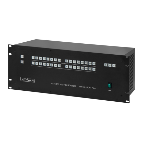
10. Appendix MX DVI-Plus Series – User's Manual 16x16 DVI MATRIX ROUTER MX16x16DVI-Plus POWER 10.4. Mechanical Drawings Side Views MX16x16DVI-Plus can be seen on the drawings but the dimensions are the same for all the three models. Dimensions are in mm. -
Page 56: Further Information
1.4. Product failures from six (6) months to the end of the warranty 3.1 13-11-2018 Drawings modified due to new labels. Laszlo period will either be repaired or replaced at the discretion of Lightware. Zsedenyi If Lightware chooses to replace the product then the replacement will be warranted for the remainder of the original unit’s warranty period.
Need help?
Do you have a question about the MX9x9DVI-Plus and is the answer not in the manual?
Questions and answers