Sign In
Upload
Download
Table of Contents
Contents
Add to my manuals
Delete from my manuals
Share
URL of this page:
HTML Link:
Bookmark this page
Add
Manual will be automatically added to "My Manuals"
Print this page
×
Bookmark added
×
Added to my manuals
Manuals
Brands
Lightware Manuals
Matrix Switcher
MX8x4DVI-Pro
User manual
Lightware MX8x4DVI-Pro User Manual
Hide thumbs
Also See for MX8x4DVI-Pro
:
Quick start manual
(2 pages)
,
Quick start manual
(2 pages)
1
2
3
4
Table Of Contents
5
6
7
8
9
10
11
12
13
14
15
16
17
18
19
20
21
22
23
24
25
26
27
28
29
30
31
32
33
34
35
36
37
38
39
40
41
42
43
44
45
46
47
48
49
page
of
49
Go
/
49
Contents
Table of Contents
Bookmarks
Table of Contents
Safety Instructions
Table of Contents
Introduction
Box Contents
Description
Features
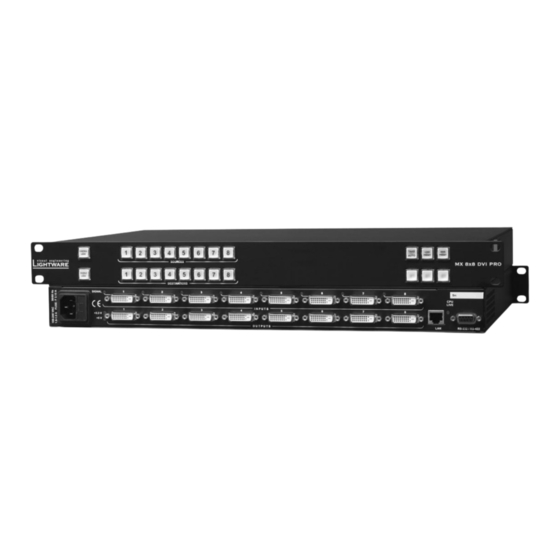
Controls and Connections
Front View
Rear View
Electrical Connections
DVI Input
RS-232/RS-422 Control Port
Technologies
Basics
Common Problems Related to EDID
Advanced Edid Management
Pixel Accurate Reclocking
Operation
Power on
Front Panel Operations
TAKE / AUTOTAKE Modes
Control Lock
Switching
Presets Operations
VIEW Current State
Output Lock
Changing and Viewing Current Protocol
Reset Factory Default DVI Signal Settings
Reset Factory Default (Static) IP Address
Software Control - Using Lightware Device Controller (Ldc)
Steps of the Installation in Case of Windows os
Steps of the Installation in Case of Mac os X
Ldc Upgrade
Establishing the Connection
Crosspoint Menu
Grid View
Tile View
Preset Operations
Edid Menu
About EDID Memory
Changing Emulated EDID
Exporting an EDID
Importing an EDID
EDID Summary Window
Editing an EDID
Creating an EDID (Easy EDID Creator)
Deleting EDID(S)
Settings Menu
Configuration
Device Information
Log
User Preferences
Terminal Window
Software Control - Using the Built-In Webpage
Establishing the Connection
The Layout of the Built-In Web
Programmers' Reference
Protocol Description
Switching and Control Commands
View Connection on a Specified Output
Switch One Input to One Output
Switch One Input to All Outputs
View Connection on All Outputs
View Mutes on All Outputs
Mute Specified Output
Unmute Specified Output
Preset Operations
Save Preset to the Specified Memory Location
Load Preset from the Specified Location
System Status Commands
View Product Type
View Serial Number
View Firmware Version of the CPU
View Firmware for All Controllers
Error Responses
Lw2 Commands - Quick Summary
Firmware Upgrade - by Lightware Matrix Firmware Updater
Install Lightware Matrix Firmware Updater Software
Front Panel Enabled Upgrade
Jumper Enabled Upgrade
Appendix
Specifications
Mechanical Drawings
Version Applicability
Warranty
Document Revision History
Advertisement
Quick Links
Download this manual
MX8x4DVI-Pro
MX8x8DVI-Pro
User's Manual
Table of
Contents
Previous
Page
Next
Page
1
2
3
4
5
Advertisement
Table of Contents
Need help?
Do you have a question about the MX8x4DVI-Pro and is the answer not in the manual?
Ask a question
Questions and answers
Related Manuals for Lightware MX8x4DVI-Pro
Matrix Switcher Lightware MX4x4DVI Quick Start Manual
(2 pages)
Matrix Switcher Lightware 4x4DVI-DL Quick Start Manual
(2 pages)
Matrix Switcher Lightware MX32x32HDMI-Pro User Manual
Video matrix switcher (108 pages)
Matrix Switcher Lightware MX6x6DVI User Manual
(75 pages)
Matrix Switcher Lightware MX6x6DVI User Manual
Computer matrix switcher (78 pages)
Matrix Switcher Lightware MX8x8DVI-Pro User Manual
(49 pages)
Matrix Switcher Lightware MX4x4DVI User Manual
User's manual for matrix switcher (44 pages)
Matrix Switcher Lightware MX16x16DVI-Plus User Manual
(89 pages)
Matrix Switcher Lightware MX9x9DVI-Plus User Manual
Multimedia matrix switcher (56 pages)
Matrix Switcher Lightware MX2-8X8-HDMI20-AUDIO User Manual
(88 pages)
Matrix Switcher Lightware MX2-8X8-HDMI20-AUDIO User Manual
Multimedia matrix switcher (72 pages)
Matrix Switcher Lightware MX2-8x8-HDMI20-L User Manual
Multimedia matrix switcher (100 pages)
Matrix Switcher Lightware MX2-4x4-HDMI20-CA User Manual
Multimedia matrix switcher (138 pages)
Matrix Switcher Lightware MX2-8x8-DH-4DPio-A User Manual
Multimedia matrix switcher (146 pages)
Matrix Switcher Lightware MX2M-FR24R User Manual
Hybrid modular multimedia matrix (126 pages)
Matrix Switcher Lightware MX2-16x8-HDMI20-R User Manual
Multimedia matrix switcher (146 pages)
This manual is also suitable for:
Mx8x8dvi-pro
Table of Contents
Print
Rename the bookmark
Delete bookmark?
Delete from my manuals?
Login
Sign In
OR
Sign in with Facebook
Sign in with Google
Upload manual
Upload from disk
Upload from URL


Need help?
Do you have a question about the MX8x4DVI-Pro and is the answer not in the manual?
Questions and answers