Table of Contents
Advertisement
Quick Links
Advertisement
Table of Contents
Troubleshooting

Subscribe to Our Youtube Channel
Related Manuals for Lightware MX2M-FR24R


Summary of Contents for Lightware MX2M-FR24R
- Page 1 User’s Manual MX2M-FR24R Hybrid Modular Multimedia Matrix v1.0 13-08-2020 ...
- Page 2 Hybrid Modular Matrix Switcher series – User's Manual Important Safety Instructions Waste Electrical & Electronic Equipment Common Safety Symbols WEEE Class I apparatus construction. Symbol Description This marking shown on the product or its literature, This equipment must be used with a mains power system with a indicates that it should not be disposed with other protective earth connection.
- Page 3 The following symbols and markings are used in the document: All presented functions refer to the indicated products. The descriptions Lightware Visual Engineering supports green technologies and have been made during testing these functions in accordance with the Eco-friend mentality. Thus, this document is made for digital usage...
-
Page 4: Table Of Contents
3.2.3. EDID Menu ..................26 8.3. Protocol Rules ................65 3.2.4. Preset Menu ..................27 8.3.1. LW3 Tree Structure and Command Structure (examples) .... 65 7. SOFTWARE CONTROL - LIGHTWARE DEVICE CONTROLLER ..44 8.3.2. General Rules ................... 65 4. INSTALLATION ................28 7.1. Install and Upgrade ..............45 8.3.3. Command Types ................66 7.2. Running the LDC ................45... - Page 5 Hybrid Modular Matrix Switcher series – User's Manual Table of Contents 8.3.9. Notifications about the Changes of the Properties ...... 67 8.7.2. Switching an Input to an Output ............. 74 8.12. System Monitoring Commands ..........82 8.3.10. Legend for the Control Commands ..........67 8.7.3. Disconnect the Output from any Input ...........
- Page 6 8.15.14. Query the Health State of the HSMB.......... 92 11. APPENDIX ..................111 8.15.15. Query the Health State of the CECU ........... 92 11.1. Specification ................112 8.16. Network Configuration ............93 11.1.1. MX2M-FR24R................112 8.16.1. Query the DHCP State ..............93 11.1.2. MX2M-4HDMI20-IB ..............112 8.16.2. Change the DHCP State ..............93 11.1.3. MX2M-DH-4DP12-IB ..............113 8.16.3. Query the IP Address ..............
-
Page 7: Introduction
Hybrid Modular Matrix Switcher series – User's Manual I ntroduction Thank you for choosing Lightware’s MX2M series devices. In the first chapter we would like to introduce the device highlighting the most important features in the below listed sections: ç Description ç... -
Page 8: Description
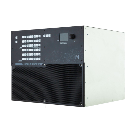
Hybrid Modular Matrix Switcher series – User's Manual 1.1. Description About the Serial Number Lightware devices contain a label indicating the unique serial number of the product. The structure is the MX2M-FR24R is a member of the Lightware MX2 modular following:... -
Page 9: Features
The matrix router starts with its latest configuration settings when powered on or after a power failure. Every setting is stored in a non-volatile memory. In the MX2M product range Lightware added a third dimension of signal routing, the Media Layers, which provide the flexibility and freedom of independent signal switching. MX2M... - Page 10 1. Introduction Hybrid Modular Matrix Switcher series – User's Manual MX2M-4OPTJ Series Boards Ethernet Control Multiple simultaneous TCP/IP connections are available with simple ASCII based protocol for 4K Video without Compression controlling and configuring the matrix router. HDMI 2.0 signal switching with 4k@60Hz and RGB 4:4:4 color space, 18 Gbit/sec bandwidth.
-
Page 11: Application Diagrams
1. Introduction Hybrid Modular Matrix Switcher series – User's Manual 1.4. Application Diagrams 1.4.1. Live Event Application Applied firmware package: v1.0.0 | LDC software: v2.4.0b3... -
Page 12: Tv Studio Application
1. Introduction Hybrid Modular Matrix Switcher series – User's Manual 1.4.2. TV Studio Application Applied firmware package: v1.0.0 | LDC software: v2.4.0b3... -
Page 13: Product Overview
2. Product Overview Hybrid Modular Matrix Switcher series – User's Manual P roduct Overview The following sections are about the physical structure of the device, input/output ports and connectors; software and hardware capabilities: ç Matrix Frame - Front View ç... -
Page 14: Matrix Frame - Front View
Easy setting and menu navigation by the jog dial control. See more details in the knob Front Panel LCD Menu Operations section. USB control USB connection for Lightware Device Controller (LDC) software. Ventilation To ensure the correct ventilation and avoid overheating provide enough free grille and dust space around the ventilation holes. -
Page 15: Matrix Frame - Rear View
MX2M-FR24R Using one or both of the PSUs at the same time is also possible. The double PSU allows to connect them for two different AC power lines to ensure the continuous power for the matrix. -
Page 16: Auxiliary (Aux) Boards
2. Product Overview Hybrid Modular Matrix Switcher series – User's Manual 2.3. Auxiliary (AUX) Boards 2.4. Input (IB) Boards 2.3.1. MX2M-AUX-8AUDIO 2.4.1. MX2M-4HDMI20-IB Ports Ports ▪ 8x 5-pole Phoenix connectors for analog audio input or output ® ▪ 4x HDMI input connectors supporting HDMI 2.0 standard Features Features ▪... -
Page 17: Mx2M-4Optj-Ib
2. Product Overview Hybrid Modular Matrix Switcher series – User's Manual 2.4.2. MX2M-4OPTJ-IB Status LEDs of the SC Connectors OPTJ 1 / OPTJ 2 / OPTJ 3 / OPTJ 4 The optical RX module is not powered. blinking (red) No fiber is connected and the laser is disabled. -
Page 18: Mx2M-Dh-4Dp12-Ib
2. Product Overview Hybrid Modular Matrix Switcher series – User's Manual 2.4.3. MX2M-DH-4DP12-IB 2.5. Output (OB) Boards 2.5.1. MX2M-4HDMI20-OB Ports ▪ 4x DisplayPort input connectors supporting DisplayPort 1.2 standard Ports Features ▪ 4x HDMI output connectors supporting HDMI 2.0 standard ▪... -
Page 19: Mx2M-4Optj-Ob
2. Product Overview Hybrid Modular Matrix Switcher series – User's Manual 2.5.2. MX2M-4OPTJ-OB Status LEDs of the SC Connectors OPTJ 1 / OPTJ 2 / OPTJ 3 / OPTJ 4 The optical TX module is not powered. blinking (red) No fiber is connected and the laser is disabled. -
Page 20: Power Supply Unit (Psu)
2. Product Overview Hybrid Modular Matrix Switcher series – User's Manual 2.6. Power Supply Unit (PSU) 2.6.1. MX2M-PSU-500-F Features ▪ 500 W power output ▪ Built-in power button One PSU is able to supply the power requirement of 16 pcs I/O boards ▪... -
Page 21: Front Panel Control
3. Front Panel Control Hybrid Modular Matrix Switcher series – User's Manual F ront Panel Control This chapter is about the operating of the device describing the functions which are available by the front panel controls: ç... -
Page 22: Front Panel Button Operations
3. Front Panel Control Hybrid Modular Matrix Switcher series – User's Manual 3.1. Front Panel Button Operations View Current State in Autotake Mode In Autotake mode only the states of the destinations The following section describes the crosspoint switching possibilities using the dedicated buttons on front can be viewed. -
Page 23: Preset Operations
3. Front Panel Control Hybrid Modular Matrix Switcher series – User's Manual 3.1.4. Preset Operations Disconnecting or Muting in Take Mode Step 1. Press and release the selected source DEFINITION: A preset stores a configuration regarding all input connections and mute state for all outputs. button. -
Page 24: Output Lock
View Locked Outputs in Autotake Mode Using Lightware matrix it is possible to lock a state of the destination. This feature prevents an accidental switching to the locked destination in the case of an important signal. Destinations can be independently In Autotake mode a destination is selected all the time. -
Page 25: Controllock
3. Front Panel Control Hybrid Modular Matrix Switcher series – User's Manual 3.2. Front Panel LCD Menu Operations Locking an Output in Autotake Mode Step 1. Press and release the required destination 3.2.1. Introduction button. Now the selected destination The company logo is displayed on the screen during the boot-up. -
Page 26: System Settings Menu
3. Front Panel Control Hybrid Modular Matrix Switcher series – User's Manual 3.2.2. System Settings Menu 3.2.3. EDID Menu Advanced EDID Management is available in the front panel LCD menu which allows to view an EDID, switch, Network or save it to the User EDID memory. -
Page 27: Preset Menu
Step 3. Select the desired memory slot and press the knob. If any other preset had been saved previously they would be also listed. See the corresponding Presets section in the Lightware Device Controller (LDC) software. Step 4. Confirm your selection by pressing the Yes. -
Page 28: Installation
4. Installation Hybrid Modular Matrix Switcher series – User's Manual I nstallation The chapter is about the installation of the device and connecting to other appliances, presenting also the mounting options and further assembly steps. ç Mounting Options ç... -
Page 29: Mounting Options
4. Installation Hybrid Modular Matrix Switcher series – User's Manual 4.1. Mounting Options Standard Rack Installation Two rack ears are supplied with the product, which are fixed on left and right side as shown in the picture. WARNING! For the correct ventilation and to avoid overheating ensure enough free space around the The default position allows mounting the device as a standard rack unit installation. -
Page 30: Board Installation And Handling
4. Installation Hybrid Modular Matrix Switcher series – User's Manual 4.2. Board Installation and Handling Auxiliary (AUX) Board Slots The first four board slots are dedicated for the auxiliary (AUX) boards which are also known as low-speed The I/O boards and the PSUs are hot-swappable. -
Page 31: Installation Of An I/O Board
4. Installation Hybrid Modular Matrix Switcher series – User's Manual 4.2.2. Installation of an I/O Board 4.3. PSU Installation WARNING! Please pay attention to the protection against electrostatic discharge Two dedicated slots are available in the matrix frame for the MX2M-PSU-500-F power supply units. The PSU when touching a board. -
Page 32: Electrical Connections
MX2M series matrix frame provides Neutrik etherCON RJ45 connectors for secure control purpose, LAN and user Ethernet access. Wiring of LAN Cables Lightware recommends the termination of LAN cables on the basis of TIA/EIA T 568 A or TIA/EIA T 568 B standards. Bottom... -
Page 33: Connector
4. Installation Hybrid Modular Matrix Switcher series – User's Manual 4.4.4. RS-232 Connector 4.4.6. HDMI Connector The matrix frame has standard 9 pin D-sub female (DE9F) miniature MX2M-4HDMI20 series I/O boards provide standard 19-pole HDMI connector for inputs and receptacle for device control purpose. -
Page 34: Connecting Steps
4. Installation Hybrid Modular Matrix Switcher series – User's Manual 4.6. Connecting Steps Connect the source / sink devices (e.g. media player) to the ports of the MX2M-AUX Interface of AUX series boards via the interface of the board. See the connection possibilities grouped by I/O board variants: ▪... -
Page 35: Powering On
4. Installation Hybrid Modular Matrix Switcher series – User's Manual 4.7. Powering On Connect the power cords to AC input of the power supply units (MX2M-PSU-500-F). INFO: The router has an internal emergency memory that stores all current settings and tie configurations. -
Page 36: Hybrid Modular Matrix Concept
5. Hybrid Modular Matrix Concept Hybrid Modular Matrix Switcher series – User's Manual H ybrid Modular Matrix Concept The following chapter describes the features of the MX2M series frame and I/O boards with few real-life examples. The topics that are described: ç... -
Page 37: Video Layer
5. Hybrid Modular Matrix Concept Hybrid Modular Matrix Switcher series – User's Manual 5.1. Video Layer Description The MX2M matrix receives video streams with the embedded audio 5.1.1. Port Diagram signal via various types of multimedia ports which are depended on the installed I/O boards. -
Page 38: Video Signal Transmission - Example
▪ Front panel buttons - see the details in the Switching Operations section; Built-in website / Lightware Device Controller (LDC) software - see the details in the Crosspoint Menu section; ▪ ▪... -
Page 39: Audio Layer
Gain setting Outputs The audio settings are available in the Built-in website / Lightware Device Controller (LDC) software (details in the The matrix is able to transmit audio streams from the Audio layer as audio embedded in the output video... -
Page 40: Audio Signal Transmission - Example
– If the selected signal is compressed (non-HBR) audio, it can be embedded to the video stream without any further action. See more details about the related settings in the Lightware Device Controller (LDC) software in the Audio Port Properties Windows section. -
Page 41: User Ethernet Mode
▪ User memory locations (U1 – U100) can be used to save custom EDIDs. MX2M-FR24R matrix switcher can be purchased with no PSU redundancy. In this case only one PSU drawer ▪ Emulated EDID list shows the currently emulated EDID for the inputs (E1-E24). The source column is installed with power supply unit (Power Drawer 1, Primary) and the Single PSU License is installed on matrix displays the memory location that the current EDID was routed from. -
Page 42: Software Control - Built-In Website
The built-in website of the Matrix Management Unit allows to connect to and control the matrix via a web browser. The range of the controlling features are the same as in the case of Software Control - Lightware Device Controller. -
Page 43: Establishing The Connection
(dynamic IP address). 6.2. The Layout of the Built-in Web The built-in web page allows the same controlling functions which are available via the Lightware Device Controller. Select a menu item on the left side; the default screen is the Crosspoint menu. ATTENTION! Please enable the pop-up windows in your browser;... -
Page 44: Software Control - Lightware Device Controller
S oftware Control - Lightware Device Controller The device can be controlled by a computer through Ethernet interface with the Lightware Device Controller (LDC). The software can be installed on a Windows PC or macOS. The application and the User’s Manual can be downloaded from www.lightware.com. -
Page 45: Install And Upgrade
The Device Discovery window appears automatically and the program checks the available updates on ▪ Ethernet Lightware’s website and opens the update window if the LDC found updates. ▪ RS-232 The current and the update version number can be seen at the top of the window and they are shown in this ▪... - Page 46 Step 2. Run the controller software; device discovery window appears automatically. Step 3. Select the MX2M-FR24R device from the discovered Ethernet devices or Serial devices; when the device is connected through RS-232 click on the Query button next to the desired serial port to display the name of the device and the serial number.
-
Page 47: Crosspoint Menu
7. Software Control - Lightware Device Controller Hybrid Modular Matrix Switcher series – User's Manual 7.4. Crosspoint Menu Device label The device label of the matrix is displayed here. It can be modified by the user to 7.4.1. Video Layer... -
Page 48: Audio Layer
7. Software Control - Lightware Device Controller Hybrid Modular Matrix Switcher series – User's Manual 7.4.2. Audio Layer 7.4.3. Legend of the Port Tiles This section helps to identify easily the various type of port and crosspoint tiles on the Crosspoint menu. - Page 49 7. Software Control - Lightware Device Controller Hybrid Modular Matrix Switcher series – User's Manual Audio Layer Port tile Description Port tile Description Crosspoint tiles Port tiles No crosspoint connection. Port is not available because there is no I/O board is installed in the related board slot.
-
Page 50: Video Port Properties Windows
7. Software Control - Lightware Device Controller Hybrid Modular Matrix Switcher series – User's Manual 7.5. Video Port Properties Windows 7.5.2. DisplayPort Input Port Properties DIFFERENCE: The following panel is available only when a MX2M-DH-4DP12-IB board is installed in the 7.5.1. HDMI / OPTJ Input Port Properties... -
Page 51: Hdmi / Optj Output Port Properties
Conversion mode (Passthrough / YCbCr 4:2:2); #colorspace ▪ Video stream information; Lightware’s Frame Detector function works like a signal analyzer and allows to determine the exact video ▪ #embedder #audio Audio source: format that is present on the port, thus it helps to identify various problems. E.g. actual timing parameters –... -
Page 52: Audio Port Properties Windows
7. Software Control - Lightware Device Controller Hybrid Modular Matrix Switcher series – User's Manual 7.6. Audio Port Properties Windows 7.6.2. Digital Audio Output Port Properties DIFFERENCE: The following panel is available only when a MX2M-4HDMI20-OB or MX2M-4OPTJ-OB board is 7.6.1. Digital Audio Input Port Properties... -
Page 53: Analog Audio Input Port Properties
7. Software Control - Lightware Device Controller Hybrid Modular Matrix Switcher series – User's Manual 7.6.3. Analog Audio Input Port Properties 7.6.4. Analog Audio Output Port Properties DIFFERENCE: The following panel is available only when a MX2M-AUX-8AUDIO board is installed in the... -
Page 54: Presets
7. Software Control - Lightware Device Controller Hybrid Modular Matrix Switcher series – User's Manual 7.7. Presets Loading a Preset Step 1. Select the Presets tab from the Crosspoint menu. Select the Crosspoint / Presets menu to open the preset operations of the matrix. -
Page 55: Edid Management Menu
7. Software Control - Lightware Device Controller Hybrid Modular Matrix Switcher series – User's Manual 7.8. EDID Management Menu 7.8.1. EDID Operations Advanced EDID Management can be accessed by selecting the EDID Management menu. There are two Changing Emulated EDID panels: left one contains Source EDIDs, right one contains Destination places where the EDIDs can be Step 1. -
Page 56: Editing An Edid
The editor can read and write all descriptors, which are defined in the standards, including the Lightware introduced a wizard-like interface for fast and easy EDID creation. With Easy EDID additional CEA extensions. Any EDID from the device’s memory or a saved EDID file can be loaded into the Creator it is possible to create custom EDIDs in four simple steps. -
Page 57: Edid Summary Window
#serialnumber Licenses MX2M-FR24R matrix switcher can be purchased with no PSU redundancy. In this case only one PSU drawer is installed with power supply unit (Power Drawer 1, Primary) and the Single PSU License is installed on matrix which results the Power Drawer 2 cannot accept the second PSU. Customers have possibility purchasing a code which makes the Single PSU License inactive. -
Page 58: Network
All system log tracks can be saved to the control computer with the Export full system log button. #log INFO: Please always download the system logs and send to the Lightware Support Team (support@lightware.com) for the most effective collaboration in the case of a troubleshooting issue. Applied firmware package: v1.0.0 | LDC software: v2.4.0b3... -
Page 59: System
7. Software Control - Lightware Device Controller Hybrid Modular Matrix Switcher series – User's Manual 7.9.4. System 7.10. Terminal Window Select the Settings / Terminal menu to open the Terminal window. #terminal #advancedview LW3 protocol help Pushing the button results a help window opening which describes the most important information about LW3 protocol commands in HTML format. -
Page 60: Health Menu
7. Software Control - Lightware Device Controller Hybrid Modular Matrix Switcher series – User's Manual 7.11. Health Menu 7.11.2. Frame 7.11.1. Overview Health menu - Frame tab Health menu - Overview tab The most important information about the matrix frame is available on the Frame tab. The firmware package version, AC power line redundancy, frame voltages, frame temperatures and the fan speeds can be checked. -
Page 61: Aux Slots
7. Software Control - Lightware Device Controller Hybrid Modular Matrix Switcher series – User's Manual 7.11.3. Aux Slots 7.11.4. Input Slots Health menu - Aux Slots tab Health menu - Input Slots tab The most important information about the auxiliary boards grouped by the board slots is available on the The most important information about the input boards grouped by the board slots is available on the Input Aux Slots tab. -
Page 62: Output Slots
7. Software Control - Lightware Device Controller Hybrid Modular Matrix Switcher series – User's Manual 7.11.5. Output Slots 7.11.6. PSU Drawer Slots Health menu - Output Slots tab Health menu - PSU Drawer Slots tab The most important information about the output boards grouped by the board slots is available on the The most important information about the PSU drawers grouped by the power drawer slots is available on Output Slots tab. -
Page 63: Failing Devices
7. Software Control - Lightware Device Controller Hybrid Modular Matrix Switcher series – User's Manual 7.11.7. Failing Devices Health menu - Failing Devices tab The most important status information about the matrix frame and the installed I/O boards is available on the Failing Devices tab. -
Page 64: Lw3 Programmers' Reference
Hybrid Modular Matrix Switcher series – User's Manual L W3 Programmers' Reference The device can be controlled through Lightware 3 (LW3) protocol commands to ensure the compatibility with other Lightware products. The supported LW3 commands are described in this chapter ç... -
Page 65: Overview
‘nodes’, ‘properties’ and ‘methods’. The MEDIA XP Advanced View of the Lightware Device Controller software is the perfect tool for browsing and learning how VIDEO the LW3 protocol can be used in practice. -
Page 66: Command Types
8. LW3 Programmers' Reference Hybrid Modular Matrix Switcher series – User's Manual 8.3.3. Command Types 8.3.4. Prefix Summary DEFINITION: The prefix is a 2-character long code that describes the type of the response. GET command The following prefixes are defined in the LW3 protocol: The GET command can be used to get the child nodes, properties and methods of a specific node. -
Page 67: Signature
8. LW3 Programmers' Reference Hybrid Modular Matrix Switcher series – User's Manual 8.3.7. Signature 8.3.9. Notifications about the Changes of the Properties DEFINITION: The signature is a four-digit-long hexadecimal value that can be optionally placed before When the value of a property is changed and the user is subscribed to the node, which the property belongs every command to keep a command and the corresponding responses together as a group. -
Page 68: System Commands
8.4.5. Query the Date and Time of the System ç GET /.ProductName The query returns with the current date and time which is set in the matrix. The format is based on the æ pr /.ProductName=MX2M-FR24R ISO 8601 standard. 8.4.2. Set the Device Label... -
Page 69: Setting The Brightness Of The Lcd Screen
8. LW3 Programmers' Reference Hybrid Modular Matrix Switcher series – User's Manual 8.4.7. Setting the Brightness of the LCD Screen 8.4.10. Removing License Command and Response Command and Response #license SET·/SYS/CECU/LCD.Brightness=<parameter> ç CALL·/MANAGEMENT/LICENSE:removeLicense() ç pw·/SYS/CECU/LCD.Brightness=<parameter> æ mO·/MANAGEMENT/LICENSE:removeLicense= æ Parameters Example <parameter>... -
Page 70: Restore The Factory Default Settings
8. LW3 Programmers' Reference Hybrid Modular Matrix Switcher series – User's Manual 8.4.13. Restore the Factory Default Settings 8.5. I/O Board Management Command and Response #factory 8.5.1. Query the Status of a Board ç CALL·/SYS:factoryDefaults() The query returns the actual status of the selected I/O board in the matrix frame. æ... -
Page 71: Query The Number Of Seated I/O Boards
8. LW3 Programmers' Reference Hybrid Modular Matrix Switcher series – User's Manual 8.5.5. Query the List of Failed I/O Boards Example ç GET /SYS/OB1.Status The query returns the list of the failed I/O boards in the matrix frame, including IB, OB, and AUX (Low Speed) boards. -
Page 72: Query The Firmware Version Of The I/O Board
8. LW3 Programmers' Reference Hybrid Modular Matrix Switcher series – User's Manual 8.5.8. Query the Firmware Version of the I/O Board 8.6.2. Switching an Input to an Output Command and Response #switch #crosspoint Command and Response #firmwareversion ç CALL·/MEDIA/XP/VIDEO:switch(<in>:<out>) ç... -
Page 73: Multiple Switching
8. LW3 Programmers' Reference Hybrid Modular Matrix Switcher series – User's Manual 8.6.5. Multiple Switching 8.6.8. Locking a Video Input The whole crosspoint can be set by sending one command as follows. Command and Response #lock Command and Response ç... -
Page 74: Locking A Video Output
8. LW3 Programmers' Reference Hybrid Modular Matrix Switcher series – User's Manual 8.6.12. Locking a Video Output 8.7.2. Switching an Input to an Output Command and Response #lock Command and Response #switch #crosspoint ç CALL·/MEDIA/XP/VIDEO:lockDestination(<out>) ç CALL·/MEDIA/XP/AUDIO:switch(<in>:<out>) æ mO·/MEDIA/XP/VIDEO:lockDestination= æ... -
Page 75: Multiple Switching
8. LW3 Programmers' Reference Hybrid Modular Matrix Switcher series – User's Manual 8.7.5. Multiple Switching 8.7.8. Locking an Audio Input The whole crosspoint can be set by sending one command as follows. #switch #crosspoint Command and Response #lock Command and Response ç... -
Page 76: Locking An Audio Output
8. LW3 Programmers' Reference Hybrid Modular Matrix Switcher series – User's Manual 8.7.12. Locking an Audio Output 8.8.2. Color Range Setting Command and Response #lock Command and Response #colorrange ç CALL·/MEDIA/XP/AUDIO:lockDestination(<out>) SET·/MEDIA/PORTS/VIDEO/<in>/PARAMETERS.InputColorRangeMode=<colorrange> ç æ mO·/MEDIA/XP/AUDIO:lockDestination= pw·/MEDIA/PORTS/VIDEO/<in>/PARAMETERS.InputColorRangeMode=<colorrange> æ Example Parameters ç... -
Page 77: Video Source Port Settings - Dp
8. LW3 Programmers' Reference Hybrid Modular Matrix Switcher series – User's Manual 8.9. Video Source Port Settings - DP 8.9.3. DP Power Setting This property allows to provide 1.5W (500mA @ 3.3W) power on DP_PWR pin. The default value is true. The following settings are valid only for the following input board: #displayport #dp Command and Response... -
Page 78: Color Space Conversion Setting
8. LW3 Programmers' Reference Hybrid Modular Matrix Switcher series – User's Manual 8.9.5. Color Space Conversion Setting 8.9.7. Restart Link Training INFO: INFO: DisplayPort signals over 18Gbps will be converted down by either truncating bit depth or This method is equal with pulling out and plug in again the DP connector. by converting RGB signal to YUV 4:2:2 12-bit signal based on user selection. -
Page 79: Hdcp Setting
8. LW3 Programmers' Reference Hybrid Modular Matrix Switcher series – User's Manual 8.9.9. HDCP Setting æ pw /MEDIA/PORTS/VIDEO/O1/PARAMETERS.ColorSpaceSetting=3 This setting allows to send non-encrypted content to a non-HDCP compliant display. See more information 8.10.2. Signal Type Setting in the HDCP Management section. -
Page 80: Hdcp Mode Setting
8. LW3 Programmers' Reference Hybrid Modular Matrix Switcher series – User's Manual 8.10.4. HDCP Mode Setting 8.11. Analog Audio Port Properties Command and Response #hdcp INFO: The analog audio ports of the MX2M-AUX-8AUDIO board can be configured as an input or output by the user. -
Page 81: Query The Output Ports Of The Board
8. LW3 Programmers' Reference Hybrid Modular Matrix Switcher series – User's Manual 8.11.2. Query the Output Ports of the Board 8.11.4. Volume Setting in dB by Steps The query returns which ports are configured as outputs out of the available eight ones. Command and Response Command and Response ç... -
Page 82: Balance Setting
8. LW3 Programmers' Reference Hybrid Modular Matrix Switcher series – User's Manual 8.11.7. Balance Setting 8.12. System Monitoring Commands Command and Response #balance TIPS AND TRICKS: All listed parameters which are listed in this section can be queried in one step with the following command: SET·/MEDIA/PORTS/AUDIO/<in|out>/PARAMETERS.Balance=<balance>... -
Page 83: Query The Signal Type
8. LW3 Programmers' Reference Hybrid Modular Matrix Switcher series – User's Manual 8.12.3. Query the Signal Type 8.12.6. Query Embedded Audio Presence SignalType property provides the type of the video signal. EmbeddedAudioPresent property indicates that embedded audio is present in the video stream. Command and Response Command and Response ç... -
Page 84: Query The Color Range Of The Stream
8. LW3 Programmers' Reference Hybrid Modular Matrix Switcher series – User's Manual 8.12.8. Query the Color Range of the Stream 8.12.10. Query the HDCP-encryption Presence Command and Response Command and Response ç GET·/MEDIA/PORTS/VIDEO/<in|out>/PARAMETERS.ColorRange ç GET·/MEDIA/PORTS/VIDEO/<in|out>/PARAMETERS.HdcpActive pr·/MEDIA/PORTS/VIDEO/<in|out>/PARAMETERS.ColorRange=<parameter> pr·/MEDIA/PORTS/VIDEO/<in|out>/PARAMETERS.HdcpActive=<parameter> æ æ... -
Page 85: Query The Maximum Supported Hdcp-Encryption Level
8. LW3 Programmers' Reference Hybrid Modular Matrix Switcher series – User's Manual 8.12.12. Query the Maximum Supported HDCP-encryption Level 8.12.14. Query the TMDS Error Counters Command and Response Command and Response ç GET·/MEDIA/PORTS/VIDEO/<in|out>/PARAMETERS.MaxSupportedHdcpVersion ç GET·/MEDIA/PORTS/VIDEO/<in|out>/PARAMETERS.TmdsErrorCounters pr·/MEDIA/PORTS/VIDEO/<in|out>/PARAMETERS.MaxSupportedHdcpVersion=<parameter> æ pr·/MEDIA/PORTS/VIDEO/<in|out>/PARAMETERS.TmdsErrorCounters=<ch0_error_cnt>;<ch1_error_cnt>; æ... -
Page 86: Saving The Settings To An Existing Preset
8. LW3 Programmers' Reference Hybrid Modular Matrix Switcher series – User's Manual 8.13.2. Saving the Settings to an Existing Preset 8.14. EDID Management Command and Response INFO: The detailed description of the parameters in the EDID management section (E, D, U, F) can be found in the EDID Management section. -
Page 87: Query The Preferred Resolution Of A User Edid
8. LW3 Programmers' Reference Hybrid Modular Matrix Switcher series – User's Manual 8.14.3. Query the Preferred Resolution of a User EDID 8.14.7. Resetting the Emulated EDIDs Command and Response Command and Response ç GET·/EDID/U/<user>.PreferredResolution ç CALL·/EDID:reset() pr·/EDID/U/<user>.PreferredResolution=<resolution> æ mO·/EDID:reset æ... -
Page 88: Query The Temperature Warnings
8. LW3 Programmers' Reference Hybrid Modular Matrix Switcher series – User's Manual 8.15.2. Query the Temperature Warnings 8.15.5. Query the Voltage Errors The query returns with a semi-colon separated list of the devices that have an active temperature warning. The query returns with a semi-colon separated list of the devices that have an active voltage error. -
Page 89: Query The Fan Warnings
8. LW3 Programmers' Reference Hybrid Modular Matrix Switcher series – User's Manual 8.15.8. Query the Fan Warnings 8.15.10. Query the PSU Drawer Warnings The query returns with a semi-colon separated list of the devices that have an active system fan warning. The query returns with a semi-colon separated list of the devices that have an active power supply unit (PSU) warning. -
Page 90: Query The Health State Of An I/O Board
8. LW3 Programmers' Reference Hybrid Modular Matrix Switcher series – User's Manual 8.15.12. Query the Health State of an I/O Board Layout of the Matrix The query returns with the actual health status information about the selected I/O board. Command and Response GETALL·/HEALTH/<board>... -
Page 91: Query The Health State Of A Psu Drawer
8. LW3 Programmers' Reference Hybrid Modular Matrix Switcher series – User's Manual 8.15.13. Query the Health State of a PSU Drawer Layout of the Matrix The query returns with the actual health status information about the selected PSU drawer. Command and Response GETALL·/HEALTH/<PSU>... -
Page 92: Query The Health State Of The Hsmb
8. LW3 Programmers' Reference Hybrid Modular Matrix Switcher series – User's Manual 8.15.14. Query the Health State of the HSMB æ pr /HEALTH/HSMB.FanSpeed1=0.00 RPM;10.00;65535.00;0.00;65535.00;0.00;0.00 æ pr /HEALTH/HSMB.FanSpeed2=0.00 RPM;10.00;65535.00;0.00;65535.00;0.00;0.00 The query returns with the actual health status information about the High Speed Motherboard (HSMB). æ... -
Page 93: Network Configuration
8. LW3 Programmers' Reference Hybrid Modular Matrix Switcher series – User's Manual 8.16. Network Configuration 8.16.4. Change the IP Address (Static) ATTENTION! Calling the ApplySettings() method after the network setting is always required. See the Command and Response details in the Apply Network Settings section. -
Page 94: Change The Gateway Address (Static)
8. LW3 Programmers' Reference Hybrid Modular Matrix Switcher series – User's Manual 8.16.8. Change the Gateway Address (Static) 8.17.2. BAUD Rate Setting Command and Response Command and Response SET·/MANAGEMENT/NETWORK.StaticGatewayAddress=<gw_address> SET·/MANAGEMENT/SERIAL.Baudrate=<baudrate> ç ç pw·/MANAGEMENT/NETWORK.StaticGatewayAddress=<gw_address> pw·/MANAGEMENT/SERIAL.Baudrate=<baudrate> æ æ Example Parameters ç... -
Page 95: Parity Setting
Parameters Parameter Parameter description Value Value description Parameter Parameter description Value Value description None None Lightware LW2 command protocol Command protocol on <protocol> Lightware LW3 command protocol the serial port <parity> Parity value Even Even Third-party command protocol Mark Mark... -
Page 96: Firmware Upgrading Of The I/O Boards
The firmware package files of all available MX2M series I/O boards are built-in into the firmware package board. of the MX2M matrix frame. The upgrading procedure can be applied inside the frame without using any external application like Lightware Device Updater V2 (LDU2). Command and Response Parameters ç... -
Page 97: Query The List Of Updating Boards
8. LW3 Programmers' Reference Hybrid Modular Matrix Switcher series – User's Manual 8.18.5. Query the List of Updating Boards The query returns with the list of the I/O boards which are currently under firmware upgrade. Command and Response ç... -
Page 98: Lw3 Protocol Commands - Quick Summary
8. LW3 Programmers' Reference Hybrid Modular Matrix Switcher series – User's Manual 8.19. LW3 Protocol Commands - Quick Summary I/O Board Management Query the Status of a Board System Commands ç GET·/SYS/<board>.Status Query the Product Name Query the Number of Seated I/O Boards ç... - Page 99 8. LW3 Programmers' Reference Hybrid Modular Matrix Switcher series – User's Manual Unmuting a Video Input Unlocking an Audio Input ç CALL·/MEDIA/XP/VIDEO:unmuteSource(<in>) ç CALL·/MEDIA/XP/AUDIO:unlockSource(<in>) Locking a Video Input Muting an Audio Output ç CALL·/MEDIA/XP/VIDEO:lockSource(<in>) ç CALL·/MEDIA/XP/AUDIO:muteDestination(<out>) Unlocking a Video Input Unmuting an Audio Output ç...
- Page 100 8. LW3 Programmers' Reference Hybrid Modular Matrix Switcher series – User's Manual Hot Plug Detect (HPD) Setting Gain Setting SET·/MEDIA/PORTS/VIDEO/<in>/PARAMETERS.EnableHPD=<hpd_setting> SET·/MEDIA/PORTS/AUDIO/<in>/PARAMETERS.Gain=<gain> ç ç HDCP Setting System Monitoring Commands SET·/MEDIA/PORTS/VIDEO/<in>/PARAMETERS.HdcpVersion=<number> ç Query Connected Device Presence Video Destination Port Settings - HDMI / OPTJ ç...
- Page 101 8. LW3 Programmers' Reference Hybrid Modular Matrix Switcher series – User's Manual Preset Handling Query the Voltage Warnings ç GET·/HEALTH.VoltageWarning Creating a New Preset Query the Voltage Errors ç CALL·/MEDIA/PRESET:create(<preset_name>,VIDEO) ç GET·/HEALTH.VoltageError Saving the Settings to an Existing Preset Query the Current Warnings ç...
- Page 102 8. LW3 Programmers' Reference Hybrid Modular Matrix Switcher series – User's Manual Network Configuration Protocol Setting SET·/MANAGEMENT/SERIAL.Protocol=<protocol> Query the DHCP State ç Recalling Factory Default Settings on the Serial Port ç GET·/MANAGEMENT/NETWORK.DhcpEnabled ç CALL·/MANAGEMENT/SERIAL:factoryDefault() Change the DHCP State Firmware Upgrading of the I/O Boards SET·/MANAGEMENT/NETWORK.DhcpEnabled=<logical_value>...
-
Page 103: Troubleshooting
9. Troubleshooting Hybrid Modular Matrix Switcher series – User's Manual T roubleshooting Usually, if the system seems not to transmit the signal as expected, the best strategy for troubleshooting is to check signal integrity through the whole signal chain starting from source side and moving forward to destination end. Link to connections/cabling section. -
Page 104: Use Cases
9. Troubleshooting Hybrid Modular Matrix Switcher series – User's Manual 9.1. Use Cases At first, check front panel LEDs and take the necessary steps according to their states. For more information about status LEDs of the matrix frame and the I/O boards refer to the Product Overview chapter. -
Page 105: How To Speed Up The Troubleshooting Process
In the case of Event Manager issue the event file and/or backup file from the Device Controller ▪ software. The more of the above information you can give us the better. Please send these information to the Lightware Support Team (support@lightware.com) to speed up the troubleshooting process. Applied firmware package: v1.0.0 | LDC software: v2.4.0b3... -
Page 106: Technologies
10. Technologies Hybrid Modular Matrix Switcher series – User's Manual Technologies The following sections contain descriptions and useful technical information how the devices work in the background. The content is based on experiences and cases we met in the practice. These sections help to understand features and technical standards like the followings: ç... -
Page 107: Edid Management
(static EDID emulation), or from the last attached monitor’s memory (dynamic EDID emulation). For example, the Lightware device can be set up to emulate a sink device, which is connected to one of the outputs. In this case, the EDID automatically changes, if the monitor is replaced with another display device (as long as it has a valid EDID). -
Page 108: Hdcp Management
To avoid unnecessary HDCP encryption, Lightware introduced the HDCP enabling/disabling function: the Not HDCP-compliant Sink 2. HDCP capability can be disabled in the Lightware device. If HDCP is disabled, the connected source will The layout is the same as in the previous case: non-HDCP compliant display device is connected to the detect that the sink is not HDCP capable, and turn off authentication. -
Page 109: Hdcp V2.2
Output Lightware device. A lower level of encryption may be applied only if the source device/content allows it - according to the HDCP standard. In this case the HDCP setting on the input port has to be set to HDCP 1.4 HDCP v1.4... -
Page 110: Pixel Accurate Reclocking
Without reclocking, sparkles, noise, and jaggies appear on the image. Lightware’s sophisticated Pixel Accurate Reclocking technology fixes more problems than general TMDS reclocking. It removes not only intra-pair skew but inter-pair skew as well. The Pixel Accurate Reclocking... -
Page 111: Appendix
11. Appendix Hybrid Modular Matrix Switcher series – User's Manual Appendix Tables, drawings, guides, and technical details as follows: ç Specification ç Factory Default Settings ç Input/Output Port Numbering ç Factory EDID List ç Audio Cable Wiring Guide ç... -
Page 112: Specification
11. Appendix Hybrid Modular Matrix Switcher series – User's Manual 11.1. Specification Weight (frame only) ......................15,9 kg (35.05 lbs) Weight (installed with two power supply units) ..............24,9 kg (54.89 lbs) 11.1.1. MX2M-FR24R Control Ports General Ethernet Ports Compliance ..............................CE Number of ports ..............................3 Electrical safety compliance ..................EN 62368-1:2014 Class II... -
Page 113: Mx2M-Dh-4Dp12-Ib
11. Appendix Hybrid Modular Matrix Switcher series – User's Manual Enclosure Operating temperature ....................0 to +50˚C (+32 to +122˚F) Material ............................1.5 mm steel Storage temperature ...................-40° to +85˚C (-40° to +185˚F) Dimensions in mm ..................... 194,5W x 208,5D x 35,5H Operating humidity .................... -
Page 114: Mx2M-4Hdmi20-Ob
11. Appendix Hybrid Modular Matrix Switcher series – User's Manual Cooling..........................2x built-in cooling fans Transmitter output OMA (Optical Modulation Amplitude) ......... -6.25 dBm (worst case) Operating temperature ....................0 to +50˚C (+32 to +122˚F) Receiver OMA (Optical Modulation Amplitude) sensitivity ........-14.25 dBm (worst case) Storage temperature ...................-40°... -
Page 115: Mx2M-4Optj-Ob
11. Appendix Hybrid Modular Matrix Switcher series – User's Manual Audio formats ..........................8 channel PCM 3D support ..............................Yes ......................Dolby TrueHD, DTS-HD Master Audio 7.1 Audio formats ..........................8 channel PCM Input cable equalization ......................Yes, +12dB fixed ......................Dolby TrueHD, DTS-HD Master Audio 7.1 Input cable equalization ...................... -
Page 116: Factory Default Settings
11. Appendix Hybrid Modular Matrix Switcher series – User's Manual 11.2. Factory Default Settings Dimmensions in inch ......................17.4W x 15.7D x 14H Weight ............................275 g (0.6 lbs) Parameter Setting/Value Audio Ports General settings Number of ports ..............................8 Display backlight Jog dial rotary direction Clockwise (CW down) -
Page 117: Input/Output Port Numbering
11.3. Input/Output Port Numbering Parameter Setting/Value Video output port settings 11.3.1. Video Input/Output Port Numbering MX2M-4HDMI20-OB / MX2M-4OPTJ-OB The following drawing describes the video port numbering of the MX2M-FR24R matrix frame. HDCP mode Auto (depends on input) Power 5V mode Signal type Auto... -
Page 118: Audio Input Port Numbering
11. Appendix Hybrid Modular Matrix Switcher series – User's Manual 11.3.2. Audio Input Port Numbering 11.3.3. Audio Output Port Numbering The following table shows the audio input numbering of the matrix. The audio port numbers are reserved The following table shows the audio output numbering of the matrix. The audio port numbers are reserved and fixed for each I/O board slots because of the following reasons: and fixed for each I/O board slots because of the following reasons: ▪... -
Page 119: Factory Edid List
11. Appendix Hybrid Modular Matrix Switcher series – User's Manual 11.4. Factory EDID List Mem. Resolution Type Mem. Resolution Type Mem. Resolution Type Mem. Resolution Type 720 x 480 @ 59.94 Hz F108 2560 x 1600 @ 59.86 Hz F141 4096 x 2160 @ 60.00 Hz... -
Page 120: Audio Cable Wiring Guide
Symmetric audio is most often referred to as balanced audio, as opposed to asymmetric, which is referred to as unbalanced audio. Lightware products are usually built with 5-pole Phoenix connectors so we would like to help users assembling their own audio cables. -
Page 121: Mechanical Drawings
11. Appendix Hybrid Modular Matrix Switcher series – User's Manual 11.6. Mechanical Drawings Top View (1:4) 11.6.1. MX2M-FR24R The following drawings present the physical dimensions of the MX2M-FR24R matrix frame. Dimensions are in mm. Front View (1:4) Applied firmware package: v1.0.0 | LDC software: v2.4.0b3... -
Page 122: Ib/Ob Boards
11. Appendix Hybrid Modular Matrix Switcher series – User's Manual 11.6.2. IB/OB Boards Side View (1:4) The following drawings present the physical dimensions of the MX2M series input (IB) and output (OB) boards. Dimensions are in mm. Front View (1:2) 14.1 15.1... -
Page 123: Aux Boards
11. Appendix Hybrid Modular Matrix Switcher series – User's Manual 11.6.3. AUX Boards 11.7. Maximum Fiber Optical Cable Distances The following drawings present the physical dimensions of the MX2M series auxiliary (AUX) boards. The following table shows the maximum allowed fiber optical cable distances. Dimensions are in mm. -
Page 124: Hashtag Keyword List
HDCP-encryption related setting #dhcp #hdmi HDMI related audio/video setting This keyword is placed at the DHCP (dynamic IP address) setting in the front panel operation, the Lightware Device Controller (LDC) and the LW3 programmer's reference section. #health System monitoring (health) related information... - Page 125 11. Appendix Hybrid Modular Matrix Switcher series – User's Manual Hashtag Keyword Description #restore Configuration cloning (restore) #serialnumber Serial number query #softreset Software reseting of the device #status Status query #switch Crosspoint switch setting #systemmonitor System monitoring (health) related information #takemode Take mode...
-
Page 126: Further Information
1.4. Product failures from six (6) months to the end of the warranty period will either be repaired or replaced at the discretion of Lightware. If Lightware chooses to replace the product then the replacement will be warranted for the remainder of the original unit’s warranty period.
Need help?
Do you have a question about the MX2M-FR24R and is the answer not in the manual?
Questions and answers