
Subscribe to Our Youtube Channel
Related Manuals for Festo MPA-L Series


Summary of Contents for Festo MPA-L Series
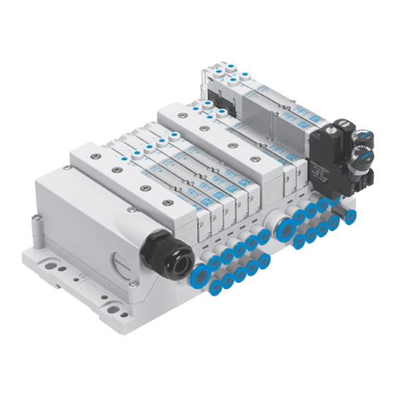
- Page 1 MPA−L valve terminal Description Pneumatic MPA−L Valve terminal Type: MPA−L−MPM−VI MPA−L−FB−VI Description 556 354 en 1008NH [722 279]...
- Page 3 ....... . . 556 354 E (Festo AG & Co. KG, D 73726 Esslingen, Federal Republic of Germany, 2010) Internet: http://www.festo.com E−Mail:...
- Page 4 ® Torx ....is a registered trade mark of the respective manufacturer in certain countries. Festo P.BE−MPAL−EN en 1008NH...
-
Page 5: Table Of Contents
........... . . 2−1 General instructions on mounting/dismantling ..... . . 2−3 Festo P.BE−MPAL−EN en 1008NH... - Page 6 ....4−6 Mounting/removing the optional manual override cover cap ... . 4−11 Festo P.BE−MPAL−EN en 1008NH...
- Page 7 ............C−1 Festo P.BE−MPAL−EN en 1008NH...
- Page 8 Contents and general safety instructions Festo P.BE−MPAL−EN en 1008NH...
-
Page 9: Intended Use
CE marking symbol. Standards and test values, which the product must comply with and fulfil, can be found in the section A.1 Technical data". The product−relevant EC directive can be found in the declaration of conformity. Festo P.BE−MPAL−EN en 1008NH... -
Page 10: Target Group
Target group This manual is intended exclusively for technicians trained in control and automation technology. Service Please consult your local Festo repair service if you have any technical problems. Structure of this manual This manual contains general basic information on fitting, installing and commissioning the valve terminal MPA−L, as... -
Page 11: Important User Instructions
... means that failure to observe this instruction may result in material damage. Additionally, the following pictogram designates text passages, which describe activities with electrostatically sensitive devices: Electrostatically sensitive devices: inappropriate handling can result in damage to components. Festo P.BE−MPAL−EN en 1008NH... - Page 12 Recommendations, tips and references to other sources of information. Accessories: Information on necessary or useful accessories for the Festo product. Environment: Information on environmentally friendly use of Festo products. Text designations Bullet points indicate activities that may be carried out · in any sequence.
-
Page 13: Terms And Abbreviations
Sub−base Plate with working lines 2 and 4 for the mounting of valves and verti cal stackings Supply plate Plate for (additional) supply of compressed air to the solenoid valves, e. g. with several pressure zones. Festo P.BE−MPAL−EN en 1008NH... - Page 14 Valve terminal MPA−L Modular performance valve manifolds light valve terminal (Type 34) multi−pin plug connection or for CPX−Terminal Vertical stacking Pneumatic components that are installed between the sub−base and the solenoid valve Tab. 0/1: Product−specific terms and abbreviations Festo P.BE−MPAL−EN en 1008NH...
-
Page 15: Overview Of Components
Overview of components Chapter 1 1−1 Festo P.BE−MPAL−EN en 1008NH... -
Page 16: The Valve Terminal Mpa
........1−24 1.7.4 Switching status displays for valves ......1−25 1−2 Festo P.BE−MPAL−EN en 1008NH... - Page 17 1. Overview of components The valve terminal MPA−L Festo supports your automation tasks at machine level with the valve terminal MPA−L. The modular structure of the valve terminal MPA−L enables you to match this valve terminal opti mally to your machine or system.
-
Page 18: Valve Terminal Design
(3/5) Vertical stacking (here: Pressure regulator plate with installed valve and Sub−base with electronic module and optional pressure gauge) valve or blanking plate Right−hand end plate Fig. 1/1: Main components of the valve terminal MPA−L 1−4 Festo P.BE−MPAL−EN en 1008NH... -
Page 19: Electrical Multi−Pin Connection
MPA−L (see Tab. 1/1). One or two solenoid coils per v alve position can be controlled. Each solenoid coil occupies one pin of the multi−pin plug. 1−5 Festo P.BE−MPAL−EN en 1008NH... -
Page 20: Versions Of The Connector
1) Note that all cables to a cable harness must be grouped to ensure EMC conformity. 2) Note that all 0 V−/24 V supply cables must be used and grouped to a cable harness. Tab. 1/1: Multi−pin plug types of the left−hand end plates 1−6 Festo P.BE−MPAL−EN en 1008NH... -
Page 21: Versions Of The Ip Protection Class
Protection class IP65, with pre−prepared cable Exclusively for the sub−D plug with 25−/44 pins. IP40 cover: open cover, protection class IP40 (In this case: Sub−D with 25 pins Tab. 1/2: Multipin sub−base and cover types 1−7 Festo P.BE−MPAL−EN en 1008NH... -
Page 22: Electrical Connection Via Cpx Terminal
CPX terminal. CPX bus node Pneumatic inter face Optional: addi tional CPX module Multipin sub− base of the CPX terminal Fig. 1/2: Electric components of the valve terminal MPA−L with CPX terminal 1−8 Festo P.BE−MPAL−EN en 1008NH... -
Page 23: Description Of Components
Operating pressure at connection (1), Vacuum at connection (5) (e.g. for vacuum switching with ejector pulse) 5/2−way double pilot valve Two monostable 3/2−way valves, normally closed, pneumatic spring return Two monostable 3/2−way valves, normally closed, pneumatic spring return 1−9 Festo P.BE−MPAL−EN en 1008NH... -
Page 24: Main And Additional Power Supply
1.5.2 Main and additional power supply The main supply of the valve terminal with operating pressure can be made via a pneumatic supply plate (see Fig. 1/3) or via the right−hand end plate with lateral ports (Tab. 1/4 below). 1−10 Festo P.BE−MPAL−EN en 1008NH... -
Page 25: Pilot Air Supply
(12/14). Note Internal pilot air supply is only permitted if the operating pressure of the last pressure zone (at the right−hand end plate) is between 3 and 8 bar . 1−11 Festo P.BE−MPAL−EN en 1008NH... - Page 26 Tab. 1/4: Right−hand end plate versions The way in which the pilot control of your valve terminal is set can be determined from Tab. 1/5. The conversion between the internal and external pilot air supply is described in Chapter 5.3.5. 1−12 Festo P.BE−MPAL−EN en 1008NH...
-
Page 27: Exhaust Air
(see Fig. 1/4). In addition to the individual sub−bases there are also the 4 off sub−bases with common 4 off electronic module. 1−13 Festo P.BE−MPAL−EN en 1008NH... - Page 28 The sub−bases with integrated pressure zone separation are in various versions with corresponding identification (see Tab. 1/6): 1−14 Festo P.BE−MPAL−EN en 1008NH...
-
Page 29: Vertical Stacking
1.5.6 Vertical stacking You can fit further pneumatic components to each valve position between the sub−base and the valve. These vertical stackings enable you to implement certain additional func tions as desired. 1−15 Festo P.BE−MPAL−EN en 1008NH... -
Page 30: Pressure Regulating Plates
The pressure regulator plates of the vertical stacking are marked on the valve terminal MPA−L with the Ident. code. This is marked on the side of the pressure regulator plate. Using Tab. 1/8 you can identify the pressure regulator plates. 1−16 Festo P.BE−MPAL−EN en 1008NH... - Page 31 The pressure regulating valve is not affected by exhausting, since the pressure is regulated upstream of the valve. The pressure regulating valve can always be adjusted because the pressure from the valve terminal is always present. 1−17 Festo P.BE−MPAL−EN en 1008NH...
- Page 32 (2) to channel (3) regulating valve Tab. 1/9: Mode of operation of the A and B pressure regulator Restrictions: The exhaust flow in the regulating direction is limited by the pressure regulating valve. 1−18 Festo P.BE−MPAL−EN en 1008NH...
- Page 33 The unregulated exhaust air is then fed via channel (4) through the pressure regulator plate and then to channel (5) and vented. Control regulator within the pressure Pressure regulator plate regulator plate Sub−base Valve Fig. 1/5: B pressure regulating valve 1−19 Festo P.BE−MPAL−EN en 1008NH...
-
Page 34: Connecting Elements
Supply connections Operating pressure" (1) Pilot air connections (12/14) and (82/84) dependent on the design Working lines (2) and (4), per valve of the right−hand end plate (see Chapter 1.5.3) Fig. 1/6: Pneumatic connecting elements 1−20 Festo P.BE−MPAL−EN en 1008NH... - Page 35 MPA−L: Sub−D multipin plug with cable Connection for functional earth Sub−D connection (here: 25−Pin versions) Fig. 1/7: Electric connecting elements of valve terminal MPA−L with multipin connection 1−21 Festo P.BE−MPAL−EN en 1008NH...
-
Page 36: Display And Control Elements
Information on the electrical connection and display compo nents of the CPX bus node is provided in the corresponding Electronics description" (see the system description for your CPX terminal, table Descriptions of the CPX terminal"). 1−22 Festo P.BE−MPAL−EN en 1008NH... -
Page 37: Identification System" (As Per Catalogue)
Information about corresponding accessories can be found in the Festo Catalogue (see www.festo.com\catalogue). 1.7.2 Manual override (MO) The manual override (MO) enables the valve to be actuated when not electrically activated or energised. -
Page 38: Pressure Regulator
On the pressure regulator plate you will find the following display and control elements: Adjusting screw for pressure regulator plate MPA1 Pressure gauge (optional) Connection for pressure gauge (can be tilted 90) Fig. 1/9: Display and control element of the pressure regulator plates 1−24 Festo P.BE−MPAL−EN en 1008NH... -
Page 39: Switching Status Displays For Valves
14 solenoid coil 12 Fig. 1/10: The assignment of LEDs and manual overrides to the solenoid coils The switching states of the solenoid coils and their signifi cance can be found in Chapter 4.4.1. 1−25 Festo P.BE−MPAL−EN en 1008NH... - Page 40 1. Overview of components 1−26 Festo P.BE−MPAL−EN en 1008NH...
-
Page 41: Mounting
Mounting Chapter 2 2−1 Festo P.BE−MPAL−EN en 1008NH... - Page 42 ....2−11 Fitting/removing optional inscription label holders ....2−13 2−2 Festo P.BE−MPAL−EN en 1008NH...
-
Page 43: General Instructions On Mounting/Dismantling
Therefore, do not touch any contact surfaces. Note Mount the valve terminal MPA−L so that there is sufficient space for heat dissipation and ensure that the maximum limits for temperatures are observed (see Technical specifications"). 2−3 Festo P.BE−MPAL−EN en 1008NH... -
Page 44: Installation/Removal On An H−Rails
Mounting, type CPA−BG−NRH. This kit contains 2 M4x10 screws and 2 clamping elements. for valve terminal MPA−Ls with CPX terminal: Mounting, type VMPAF−FB−BG−NRH. This set consists of 3 clamping components, two M4x12 screws and one M4x10 screw. 2−4 Festo P.BE−MPAL−EN en 1008NH... - Page 45 100 mm. 3. Mount the H−rail clamping units at all required mounting points (see Tab. 2/1). Make sure that the clamping ele ment (see Fig. 2/1, 3) lies horizontally to the H−rail. 2−5 Festo P.BE−MPAL−EN en 1008NH...
- Page 46 H−rail (see Fig. 2/2, Arrow A) and tighten the locking screws of the H−rail clamping compo nent with1.3 Nm ±10%, to protect the v alve terminal MPA−L against slipping or sliding down. 2−6 Festo P.BE−MPAL−EN en 1008NH...
- Page 47 H−rail. 2. Swing the valve terminal MPA−L forwards from the H−rail (see Fig. 2/3, arrow A). 3. Lift the valve terminal MPA−L off the H−rail (see Fig. 2/3, arrow B). 2−7 Festo P.BE−MPAL−EN en 1008NH...
- Page 48 2. Mounting H−rail Retaining screw of the H−rail clamping unit Clamping component of the H−rail clamping unit Mounting surface Fig. 2/3: Dismantling the valve terminal MPA−L 2−8 Festo P.BE−MPAL−EN en 1008NH...
-
Page 49: Wall Installation/Removal
Chapter 2.3.2. 2.3.1 Standard mounting points of the valve terminal The end plates, the multipin sub−base and pneumatic interface contain holes for fitting the terminal onto a wall (see Tab. 2/2). 2−9 Festo P.BE−MPAL−EN en 1008NH... - Page 50 2. Make sure there is sufficient space for connecting the power supply cables and tubing. 3. Drill mounting holes in the mounting surface. 4. Fasten the valve terminal MPA−L with M4 or M6 screws of sufficient length to the mounting surface (see Tab. 2/2). 2−10 Festo P.BE−MPAL−EN en 1008NH...
-
Page 51: Additional Mountings Of The Valve Terminal
130 mm. CPX terminal A CPX terminal on the valve terminal MPA−L with four or more interlinking blocks must be fitted with additional mounting clips, type CPXBG−RW−..., (see CPX system description). 2−11 Festo P.BE−MPAL−EN en 1008NH... - Page 52 2. Rotate (1.) the mounting in the direction of the slots of the connection/supply plates (see Fig. 2/4). 3. Press up (2.) the mounting on the connection/supply plates until the hooks snap into the slots. 2−12 Festo P.BE−MPAL−EN en 1008NH...
-
Page 53: Fitting/Removing Optional Inscription Label Holders
For identification of the valves or the working ports labels can be attached to the sub−bases, if corresponding Inscrip tion label holders type VMPAL−ST−AP−10, are fitted. Information about accessories can be found in the Festo Catalogue (see www.festo.com\catalogue). Mounting Proceed as follows: 2−13... - Page 54 Remove the label holder from the sub−base, using a cross · slot screwdriver if necessary, (see Fig. 2/6) by suppor ting on the valve located above. Label holder with label Fig. 2/6: Dismantling the label holder 2−14 Festo P.BE−MPAL−EN en 1008NH...
-
Page 55: Installation
Installation Chapter 3 3−1 Festo P.BE−MPAL−EN en 1008NH... - Page 56 ... 3−28 3.6.2 Valve terminal MPA−L with CPX terminal ..... 3−28 3−2 Festo P.BE−MPAL−EN en 1008NH...
-
Page 57: Installation
3.1.2 Operation with lubricated compressed air Operate system equipment with unlubricated compressed air, if possible. This is better for the environment. Festo pneu matic valves and actuators have been designed so that, if used as intended, they will not require additional lubrication and will still achieve a long service life. - Page 58 Unsuitable additional oil and an excessive oil content in the compressed air reduce the service life of the valve ter minal. Use Festo special oil OFSW−32 or the alternatives listed in the Festo catalogue (as specified in DIN 51524−HLP32; basic oil viscosity 32 CST at 40 °C).
- Page 59 Another indicator is the coloration or the condition of the exhaust air silencer. Distinctly yellow colour ing of the filter element or drops of oil on the silencer indicate that the lubricator setting is too high. 3−5 Festo P.BE−MPAL−EN en 1008NH...
-
Page 60: General Instructions On Installation
The back pressures can lead to pneumatic actuation of other valves, especially with un switched 3/2−way valves that are normally closed. 3−6 Festo P.BE−MPAL−EN en 1008NH... -
Page 61: Connecting The Valve Terminal Mpa−L
(1) for all solenoid coils. When operating the valve terminal with several pressure zones the inter nal pilot air supply is taken from the pressure zone, which is directly adjacent to the right−hand end plate (see Fig. 3/1 and Fig. 3/2). 3−7 Festo P.BE−MPAL−EN en 1008NH... -
Page 62: Valve Terminal Mpa−L With Pressure Zone Separation
For each additional pressure zone a special sub−base is re quired for separation and a special pneumatic supply plate is required for supply (see Fig. 3/1 and Fig. 3/2). 3−8 Festo P.BE−MPAL−EN en 1008NH... - Page 63 (here: for the separation of Right−hand end plate (here: Version channels (1) and (3/5) between without side connections) pressure zone 1 and pressure zone 2) Fig. 3/1: Example: Valve terminal MPA−L with three pressure zones 3−9 Festo P.BE−MPAL−EN en 1008NH...
-
Page 64: Setting The Pressure Regulating Valve
3.3.3 Setting the pressure regulating valve Using the adjusting screw on the pressure regulator plate (see Fig. 3/3) you can change the flow (see also Flow diagrams of the pressure regulator valve plates" in Appendix A). 3−10 Festo P.BE−MPAL−EN en 1008NH... -
Page 65: Vacuum/Low Pressure Operation
Fig. A/1. If valves are used for switching a vacuum, then filters must be used in the suction line to avoid operative malfunctions caused by foreign matter sucked into the line. 3−11 Festo P.BE−MPAL−EN en 1008NH... - Page 66 3) In accordance with diagrams in Appendix A, Fig. A/1 Tab. 3/1: Valve sub−bases, suitable for vacuum and low pressure The pressure ranges of individual valve types can be found Tab. A/4 in the Technical Specification.. 3−12 Festo P.BE−MPAL−EN en 1008NH...
-
Page 67: Connecting The Pneumatic Lines
Tab. 3/2: Connections to the valves with Ident. code X and W Connecting the pneumatic lines As pneumatic connection elements, terminal screws and threadless cartridges with safety slot and and clamp strap are used in the MPA−L valve (seeFig. 3/4 and Tab. 3/3). 3−13 Festo P.BE−MPAL−EN en 1008NH... - Page 68 If elbow connectors or multiple distributors are used, the air flow will be reduced slightly. (3/5) (12/14) (82/84) Fig. 3/4: Pneumatic connections of the valve terminal MPA−L (here: End plate for fitting in exhaust ports) 3−14 Festo P.BE−MPAL−EN en 1008NH...
-
Page 69: Installation/Replacement Of The Threadless Cartridges
3. Keep the cartridges in the pressed in state and insert a suitable clamp strap in the slot (see Fig. 3/5). Obser ve the guide steps on both sides. The clamp strap must slot into the end position. 3−15 Festo P.BE−MPAL−EN en 1008NH... - Page 70 Danger of injury by automatic loosening of parts under pressure. On pneumatic actuation cartridges can loosen and be ejected at high speed, if the clamp strap is not inserted securely in the safety slot. After installation check each cartridge for secure seating. 3−16 Festo P.BE−MPAL−EN en 1008NH...
- Page 71 3. Installation Fig. 3/5: Assembly of clamp straps for positive locking of the cartridges 3−17 Festo P.BE−MPAL−EN en 1008NH...
-
Page 72: Laying The Tubing
2. Check the secure attachment of the hose to the cartridge. 3. For reasons of clarity, bundle the tubing together with: Tube straps or Multiple tubing holders Cartridge fitting Locking ring Fig. 3/6: Fitting the tubing 3−18 Festo P.BE−MPAL−EN en 1008NH... - Page 73 1. Identify all pneumatic hoses to avoid confusion when reconnecting. 2. Press down the locking ring of the cartridge e. g. with a screwdriver or Festo QSO releasing tool (see Fig. 3/7). 3. Remove the tubing from the cartridge. Cartridge fitting Locking ring Fig.
-
Page 74: Common Pneumatic Lines
First valve terminal MPA−L Common exhaust lines (3/5) Central pilot air exhaust tubing(82/84) Central exhaust line (3/5) Second valve terminal MPA−L Common exhaust lines (82/84) Fig. 3/8: Common lines with non−return valves 3−20 Festo P.BE−MPAL−EN en 1008NH... -
Page 75: Connecting The Electric Cables
CPX system manual. Detailed instructions on connecting the CPX modules (bus node, I/O modules etc.) can be found in the relevant descrip tions for the CPX module (see CPX system description, table Descriptions of the CPX terminal"). 3−21 Festo P.BE−MPAL−EN en 1008NH... - Page 76 Observe in addition the supplementary information in the CPX system description. This serves to avoid interference due to electromagnetic influences and and ensures electromagnetic compatibility in accordance with EMC directives. 3−22 Festo P.BE−MPAL−EN en 1008NH...
- Page 77 MPA−L with multi−pin plug connection to the right−hand end plate 2 MPA−L with CPX terminal to the left−hand end plate 1 to the right−hand end plate 2 Tab. 3/4: Earth connections of the valve terminal MPA−L 3−23 Festo P.BE−MPAL−EN en 1008NH...
-
Page 78: Address Assignment Of The Valves
Address assignment does not depend on whether blanking plates or valve plates are fitted. If a valve position occupies 2 addresses, the following applies: Pilot solenoid 14 occupies the less significant ad dress. Pilot solenoid coil 12 occupies the more significant address 3−24 Festo P.BE−MPAL−EN en 1008NH... - Page 79 (black, for 4 MPA1 valves each with two solenoid each with two solenoid coils) VMPA1−EVAP−10−2−4 (black, for 4 MPA1 valves each with two solenoid each with two solenoid coils) VMPA1−EVAP−10−1 (grey, for an MPA1 valve with a solenoid coil) 3−25 Festo P.BE−MPAL−EN en 1008NH...
- Page 80 2) Mixed operation is not permitted. Tab. 3/6: Example: Address assignment of an valve terminal MPA−L with 25 pin multi−pin plug connection and 10 valve positions Note Addresses may be shifted if the valve terminal is extended. 3−26 Festo P.BE−MPAL−EN en 1008NH...
- Page 81 VMPA1−EVAP−10−2−4 electronic Unused/reserved valve position modules assigned two addresses per valve position Supply plate with MPA1−EVAP−20−SP electronic module (no address assigned) Fig. 3/9: Example: Address assignment for valve terminal MPA−L with multi−pin plug connection (view) 3−27 Festo P.BE−MPAL−EN en 1008NH...
-
Page 82: Valve Terminal Mpa−L With Multi−Pin Plug Connection
Rotary switch under a cover cap (torque: 0.5 Nm ± 10 %) Inscription field Fault LED (red) Connecting plug to the CPX interlinking blocks Fig. 3/10: Display and connecting elements on the pneumatic interface 3−28 Festo P.BE−MPAL−EN en 1008NH... - Page 83 This is not necessary if previously a sufficiently large ad dress space for the expansion has been reserved. 3−29 Festo P.BE−MPAL−EN en 1008NH...
- Page 84 Further instructions on addressing the pneumatic modules of the valve terminal MPA−L with CPX terminal can be found in the electronics manual for the module (see CPX system de scription, table Manuals on the CPX terminal"). 3−30 Festo P.BE−MPAL−EN en 1008NH...
-
Page 85: Commissioning
Commissioning Chapter 4 4−1 Festo P.BE−MPAL−EN en 1008NH... - Page 86 ........4−13 4.4.3 Operating states of the pneumatic system ....4−15 4−2 Festo P.BE−MPAL−EN en 1008NH...
-
Page 87: Commissioning
This can cause damage to the machine or system and even injury to persons. Operate the valve terminal with an external pilot air · supply (3 ... 8 bar). Branch the pilot air supply before the soft−start valve (see Fig. 4/1). 4−3 Festo P.BE−MPAL−EN en 1008NH... - Page 88 Externally supplied pilot air supply (3 to 8 bar), branched before the soft−start valve Soft−start valve (slow build up in pressure of complete supply) Fig. 4/1: Example of valve−cylinder combination with slow pressure build−up of the complete system 4−4 Festo P.BE−MPAL−EN en 1008NH...
- Page 89 (1) start valve Branched up slowly fast before pressure slowly stream of the soft− rise at (1) start valve Tab. 4/1: Effects of slow start−up pressurisation 4−5 Festo P.BE−MPAL−EN en 1008NH...
-
Page 90: Checking The Valves And The Valve/Actuator Combination
Commissioning the pneumatic components by means of the manual override is described below. Commissioning of the CPX terminal is described in the appropriate description for the CPX bus node (see CPX system description, table Descriptions of the CPX terminal"). 4−6 Festo P.BE−MPAL−EN en 1008NH... - Page 91 A valve that has been switched by an electric signal cannot be reset by the manual override. The electric signal is dominant in this case. Reset the electric signal before actuating the manual · override. Proceed as follows: 1. Switch on the compressed air supply. 4−7 Festo P.BE−MPAL−EN en 1008NH...
- Page 92 If the manual override is in the actuated state, it is not possible to reset the valve to its neutral position with an electric signal. The manual override is dominant in this case. 4. Switch off the compressed air supply after testing the valves. 4−8 Festo P.BE−MPAL−EN en 1008NH...
- Page 93 Pilot valve returns to the neutral posi tion and so too does the monostable power valve (not for bistable valves, code J). Tab. 4/3: Non−locking operation of the manual override 4−9 Festo P.BE−MPAL−EN en 1008NH...
- Page 94 Put down the screwdriver. Pilot valve returns to the neutral posi · tion and so too does the monostable power valve (not for bistable valves code J). Tab. 4/4: Detenting operation of the manual override 4−10 Festo P.BE−MPAL−EN en 1008NH...
-
Page 95: Mounting/Removing The Optional Manual Override Cover Cap
3. Clip the manual override cover caps into the recesses in the manual overrides (see Fig. 4/2). Manual override cover caps Manual override (MO) Fig. 4/2: Mounting the MO cover caps 4−11 Festo P.BE−MPAL−EN en 1008NH... - Page 96 Use a suitable screwdriver to lift the manual override · cover caps out of the manual overrides (see Fig. 4/3). Fig. 4/3: Dismounting the manual override cover caps Further information can be found in the assembly instructions enclosed with the cover caps. 4−12 Festo P.BE−MPAL−EN en 1008NH...
-
Page 97: Troubleshooting
Tab. 4/5: Meaning of the LED display 4.4.2 Impairment of functions After switching on the compressed air supply or when subse quently testing the individual valves, you can learn the following about the operating status of the pneumatic system: 4−13 Festo P.BE−MPAL−EN en 1008NH... - Page 98 For valve terminals which must be operated with closed−loop regulated external pilot air: After switching on again, check the pilot pressure (if necessary, · set as a factor of the operating pressure, see chapter 3) Tab. 4/6: Function impairment of the pneumatic system 4−14 Festo P.BE−MPAL−EN en 1008NH...
-
Page 99: Operating States Of The Pneumatic System
MPA−L Slow start−up after If control signals are present, the pi EMERGENCY STOP lot air supply must have a pressure of 3 ... 8 bar immediately after being switched on Tab. 4/7: Pneumatic operating states 4−15 Festo P.BE−MPAL−EN en 1008NH... - Page 100 4. Commissioning 4−16 Festo P.BE−MPAL−EN en 1008NH...
-
Page 101: Conversion And Maintenance
Conversion and maintenance Chapter 5 5−1 Festo P.BE−MPAL−EN en 1008NH... - Page 102 ........5−24 5−2 Festo P.BE−MPAL−EN en 1008NH...
-
Page 103: Conversion And Maintenance
The specified torques must be observed. Fittings must be mounted free of offset and mechanical tension. Check the seals for damage (to maintain IP 65). The contact surfaces must be dry and clean (sealing effect, avoid leakage and contact errors). 5−3 Festo P.BE−MPAL−EN en 1008NH... -
Page 104: Maintaining The Valve Terminal Mpa−L
2. Clean the flat plate silencer with petrol or petroleum or replace it with a new insert. 3. Fasten the flat plate silencer only with the original screws. Tighten them to 1.4 Nm ±10 %. 5−4 Festo P.BE−MPAL−EN en 1008NH... -
Page 105: Replacing Valves Or Cover Plates
1. Check the seals for damage, especially the cord seals. 2. Replace seals if they are damaged. 3. Make sure that the cord seal between the sub−base and components is in the correct position: The cord seal must sit in the component cut−outs. 5−5 Festo P.BE−MPAL−EN en 1008NH... - Page 106 Valve or cover plate Cord seal Sub−base Fig. 5/2: Mounting valve plates or cover plates 4. Place the component on the sub−base. 5. Screw the component at first slightly and then tighten to 0.25 Nm ±20 % 5−6 Festo P.BE−MPAL−EN en 1008NH...
-
Page 107: Conversion Of The Mpa−L Valve Terminal
(see Tab. 5/1). Information on permitted possibilities of combining MPA−L components and accessories can be found in the Festo Cata logue (see www.festo.com\catalogue). 5.3.1 Tie rod system The mechanical connection between the modules of the valve terminal MPA−L is achieved via a tie rod system in the sub−... - Page 108 For this extension pieces are screwed in between the threaded rod and thread sleeve. For sub−bases, 4x sub−bases and pneumatic supply plates corresponding extension pieces are available (see Tab. 5/1). 5−8 Festo P.BE−MPAL−EN en 1008NH...
- Page 109 Use extension piece, type VMAL−ZAE−10, and tie rod screw. For extension of these special solutions use the correspon ding extension pieces (see Tab. 5/1) and screw them directly between the tie rod screws and available components. 5−9 Festo P.BE−MPAL−EN en 1008NH...
- Page 110 One tie rod screw sub−base/supply plates the extension pieces must be replaced by the standard setup. Tab. 5/2: Standard setup of the tie rod system and special solutions for short valve terminal MPA−Ls with extension possibilities 5−10 Festo P.BE−MPAL−EN en 1008NH...
-
Page 111: Exchange Sub−Base, Supply Plate Or Extend Or Exchange Right−Hand End Plate
The maximum number of controllable solenoid coils is limited by the connection option (multi−pin plug type or CPX terminal, see Chapter 1.3 and 1.4). For 32 controllable solenoid coils the maximum number of sub−bases (X can be calculated as follows: max) 5−11 Festo P.BE−MPAL−EN en 1008NH... - Page 112 The released sub−bases are now only held together by the electrical interlinking. 5. First withdraw the components on the right from the com ponents to be exchanged or extended. 6. If necessary withdraw the components to be exchanged and replace them. 5−12 Festo P.BE−MPAL−EN en 1008NH...
- Page 113 Allen key, size 2.5, hand tight. Tighten the screws to a torque of 1.7 Nm ±10% and then check the torque on all three screws, as the torque on the screws can change during the tightening process. 5−13 Festo P.BE−MPAL−EN en 1008NH...
-
Page 114: Replace The Electronic Module
Each sub−base, 4x sub−base and supply plate is fitted with a separate electronic module. A list of all available electronic modules can be found in Chapter 3.6. To exchange an electronic module the valve terminal MPA−L must be partially dismantled (see Chapter 5.3.2). 5−14 Festo P.BE−MPAL−EN en 1008NH... -
Page 115: Conversion Between Ducted And Unducted Exhaust Air
Proceed as follows to convert to unducted exhaust air: 1. Loosen the 4 attachment screws of the exhaust plate and remove the exhaust plate including the cord seal from the supply plate. 5−15 Festo P.BE−MPAL−EN en 1008NH... -
Page 116: Conversion Between Internal And External Pilot Air Supply
MPA−L are supplied with a common pilot air supply. The pilot air supply that your valve terminal MPA−L is set for can be determined from the position of the selector plate (see Chapter 1.5.3). 5−16 Festo P.BE−MPAL−EN en 1008NH... - Page 117 3. Tighten screw (torque 3.5 Nm ±10%). Right−hand end plate with lateral ports Proceed as follows when converting: 1. Unscrew the screws of the selector plate (see Fig. 5/7) and remove selector plate. 5−17 Festo P.BE−MPAL−EN en 1008NH...
-
Page 118: Converting The Valve Terminal Mpa−L To Different Pressure Zones
5.3.6 Converting the valve terminal MPA−L to different pressure zones For the conversion you will require at least the following components for each pressure zone: Sub−base with desired pressure zone separation (see Chapter 1.5.5) Pneumatic supply plate with exhaust plate and flat plate silencer 5−18 Festo P.BE−MPAL−EN en 1008NH... -
Page 119: Conversion Of The Left−Hand End Plate Of Ip40 On Ip65 Cover
4. Connect the electrical cables according to the short description provided with the product. 5.3.8 Conversion of the outlet direction of the multi−pin cable Applies only to the versions of the valve terminal MPA−L with multi−pin connection and IP65 cover. 5−19 Festo P.BE−MPAL−EN en 1008NH... - Page 120 2. Push the M20x1.5 nut provided over the multi−pin cable. 3. Guide the multi−pin cable through the hole of the desired cable exit direction. 4. Push the cable connector and the cover nut over the multi−pin cable. 5−20 Festo P.BE−MPAL−EN en 1008NH...
- Page 121 M20x1.5 locking screw and screw tight the cable connector (torque 3 Nm ±10%). 4. Guide the multi−pin cable through the M20x1.5 locking screw and out through the cover. 5−21 Festo P.BE−MPAL−EN en 1008NH...
-
Page 122: Conversion Of The End Plate Between Multi−Pin And Cpx Connection
Allen key size 2.5 (see Fig. 5/4). 4. Then loosen and remove the three screws of the tie rod. The released sub−bases are now only held together by the electrical interlinking. 5. Remove all components from the the left−hand end plate. 5−22 Festo P.BE−MPAL−EN en 1008NH... - Page 123 3. Carry out the remaining assembly steps in the reverse order to dismantling. 4. Mount the valve terminal on the mounting surface (see Chapter 2). 5. Then fit the pneumatic and electrical connections (see Chapter 3). 5−23 Festo P.BE−MPAL−EN en 1008NH...
-
Page 124: Replace The Pneumatic Interface
MPA−L from its fastening surface (see Chapter 2). 2. Place the valve terminal MPA−L on a flat working surface. 3. Disassemble the pneumatic side of the valve terminal MPA−L (see Chapter 5.3.9). 5−24 Festo P.BE−MPAL−EN en 1008NH... - Page 125 Screwdriver Fig. 5/10: Dismantling on the side of the CPX terminal Information about conversion and extension of the CPX terminal can be found in the CPX system manual type P.BE−CPX−SYS−..5−25 Festo P.BE−MPAL−EN en 1008NH...
- Page 126 Use the bearing surface for the H−rail to align the component correctly. It is easier to align if you use an H−rail. 4. Tighten the two tie rod screws uniformly using an Allen key, size 3, (torque 2 Nm ±0.3 Nm). 5−26 Festo P.BE−MPAL−EN en 1008NH...
- Page 127 5. Conversion and maintenance 5. Mount the valve terminal on the mounting surface (see Chapter 2). 6. Then fit the pneumatic and electrical connections (see Chapter 3). 5−27 Festo P.BE−MPAL−EN en 1008NH...
- Page 128 5. Conversion and maintenance 5−28 Festo P.BE−MPAL−EN en 1008NH...
- Page 129 Technical appendix Appendix A A−1 Festo P.BE−MPAL−EN en 1008NH...
-
Page 130: A. Technical Appendix
..........A−12 A−2 Festo P.BE−MPAL−EN en 1008NH... -
Page 131: A.1 Technical Data
Flat plate silencer with cover 1.3 ±10% Exhaust plate 1.0 ±10% Sub−base Valve 0.25 ±20% Right−hand end plate Selector plate, round 3.5 ±10% Selector plate, square 2.2 ±10% Tie rod Threaded rod/sleeve, screw 1.7 ±10% A−3 Festo P.BE−MPAL−EN en 1008NH... - Page 132 (dependent on plug type, see Chapter 1.3) Valve terminal MPA−L with CPX terminal: Per valve position one or two solenoid coils and within the valve terminal MPA−L maximum 32 solenoid coils can be controlled via the CPX terminal. A−4 Festo P.BE−MPAL−EN en 1008NH...
- Page 133 0.35 mm Amplitude at 10 ... 60 Hz; ±30 g for 11 ms duration; 5 g acceleration at 60 ... 150 Hz 5 shocks in each direction Tab. A/3: Values for vibration and shock as per DIN/IEC 68 A−5 Festo P.BE−MPAL−EN en 1008NH...
- Page 134 Valve location Ident. codes D, H, i, K and N at connection (1): 3 ... 10 bars All valve plates on connection (12/14): see relevant diagrams Manual override Detenting or non−detenting Tab. A/4: Medium and pressure range A−6 Festo P.BE−MPAL−EN en 1008NH...
- Page 135 Operating pressure at port (1) p1 [bar] Fig. A/2: Diagram: Required pilot pressure relative to operating pressure with external pilot air supply and using valve sub−bases with Ident. codes DS, HS, KS and NS A−7 Festo P.BE−MPAL−EN en 1008NH...
- Page 136 (1) p1 [bar] Fig. A/3: Diagram: Required pilot pressure related to the operating pressure with exter nal pilot air and use of valve plates with Ident. codes B, E, G, J, M, W and X A−8 Festo P.BE−MPAL−EN en 1008NH...
- Page 137 2) Flow direction 1 } 4 or 4 } 3/5 not with valves having Ident. codes I, W and X. 3) Values for the mid−position are quoted in brackets Tab. A/5: Nominal flow rates and valve switching times for MPA1 A−9 Festo P.BE−MPAL−EN en 1008NH...
- Page 138 (for each solenoid coil) at 24 V 50 mA/20 ms Nominal pick−up current/duration 10 mA Nominal current with current reduction Tab. A/7: Technical specifications on electric components, valve terminal MPA−L with multi−pin plug connection A−10 Festo P.BE−MPAL−EN en 1008NH...
- Page 139 Maximum current consumption per solenoid coil at load voltage V at 24 V Nominal pick−up current/duration 50 mA/20 ms Nominal current with current reduction 10 mA Tab. A/8: Technical specifications on electric components, valve terminal MPA−L with CPX terminal A−11 Festo P.BE−MPAL−EN en 1008NH...
-
Page 140: A.2 Festo Accessories
A. Technical appendix Festo accessories The complete range of accessories can be found in the Festo Catalogue (see www.festo.com\catalogue). A−12 Festo P.BE−MPAL−EN en 1008NH... - Page 141 Supplementary overview of components Appendix B B−1 Festo P.BE−MPAL−EN en 1008NH...
-
Page 142: B. Supplementary Overview Of Components
Overview of valve position components ......B−3 B−2 Festo P.BE−MPAL−EN en 1008NH... -
Page 143: B.1 Overview Of Valve Position Components
2/2−way valves ID code: D Function: Two monostable 2/2−way valves, normally closed Pneumatic spring return 12/14 82/84 ID code: DS Function: Two monostable 2/2−way valves, normally closed Mechanical spring return 82/84 12/14 B−3 Festo P.BE−MPAL−EN en 1008NH... - Page 144 1) Note: If this 2/2−way valve (Ident. code I) is also operated with other valves on the MPA−L valve terminal, then this 2/2−way valve must be operated in a separate pressure zone with a separate exhaust air channel (5). Tab. B/1: 2/2−way valves B−4 Festo P.BE−MPAL−EN en 1008NH...
- Page 145 Mechanical spring return 82/84 12/14 ID code: K Function: Two monostable 3/2−way valves, normally closed Pneumatic spring return 12/14 82/84 ID code: KS Function: Two monostable 3/2−way valves, normally closed Mechanical spring return 12/14 82/84 B−5 Festo P.BE−MPAL−EN en 1008NH...
- Page 146 1x monostable 3/2−way valve, normally open, (14) external compressed air supply Pneumatic spring return (82/84) (12/14) ID code: X Function: 1x monostable 3/2−way valve, normally (14) closed, external compressed air supply Pneumatic spring return (12/14) (82/84) Tab. B/2: 3/2−way valves B−6 Festo P.BE−MPAL−EN en 1008NH...
- Page 147 B. Supplementary overview of components 5/2−way valves ID code: J Function: A bistable 5/2−way valve (12/14) ID code: M Function: One monostable 5/2−way valve Pneumatic spring return (12/14) Tab. B/3: 5/2−way valves B−7 Festo P.BE−MPAL−EN en 1008NH...
- Page 148 Tab. B/4: 5/3−way valves Note In a currentless state 5/3−way valves assume the mid− position by means of spring force. If both solenoid coils on 5/3−way valves are energised simultaneously, the valve remains in the previous switching position. B−8 Festo P.BE−MPAL−EN en 1008NH...
- Page 149 Pressure regulator plate for port 4 (A controller) ID code: PG or PB Function: Regulates the operating pressure in channel 4 after the directional control valve. 14 5 3 12 Tab. B/5: Pressure regulator plates for regulating outputs 1, 2 and 4 B−9 Festo P.BE−MPAL−EN en 1008NH...
- Page 150 B. Supplementary overview of components B−10 Festo P.BE−MPAL−EN en 1008NH...
- Page 151 Index Appendix C C−1 Festo P.BE−MPAL−EN en 1008NH...
-
Page 152: C. Index
............C−1 C−2 Festo P.BE−MPAL−EN en 1008NH... - Page 153 ..... A−6 Control elements, pneumatic ..... 1−22 C−3 Festo P.BE−MPAL−EN en 1008NH...
- Page 154 Clean or replace ....... 5−4 C−4 Festo P.BE−MPAL−EN en 1008NH...
- Page 155 ........A−11 Low−pressure operation ..... 3−11 , 4−15 C−5 Festo P.BE−MPAL−EN en 1008NH...
- Page 156 ......A−11 Optimisation, Flow rate ......3−7 C−6 Festo P.BE−MPAL−EN en 1008NH...
- Page 157 ....3−10 Pressure zones ....1−13 , 3−8 , 4−15 , 5−18 C−7 Festo P.BE−MPAL−EN en 1008NH...
- Page 158 Switching times ....... . . A−9 C−8 Festo P.BE−MPAL−EN en 1008NH...
- Page 159 User instructions ....... . . C−9 Festo P.BE−MPAL−EN en 1008NH...
- Page 160 ....2−9 Weights, Components ......A−4 C−10 Festo P.BE−MPAL−EN en 1008NH...
Need help?
Do you have a question about the MPA-L Series and is the answer not in the manual?
Questions and answers