Table of Contents
Advertisement
Advertisement
Table of Contents

Related Manuals for Festo MPAC-VI


Summary of Contents for Festo MPAC-VI
- Page 1 Valve terminal MPAC-VI Pneumatics description 8023740 2017-12a [8075694]...
- Page 2 Essential or useful accessories Information on environmentally sound usage Text designations: • Activities that may be carried out in any order 1. Activities that should be carried out in the order stated – General lists Festo – MPAC-VI-EN – 2017-12a –...
-
Page 3: Table Of Contents
..........Festo – MPAC-VI-EN – 2017-12a – English... - Page 4 ..........Conversion of the outlet orientation for the electrical connection ....Festo – MPAC-VI-EN – 2017-12a – English...
- Page 5 ............... . Festo – MPAC-VI-EN – 2017-12a – English...
- Page 6 Supplementary material information regarding food safety Tab. 1 Documents relating to the product For all available product documentation è www.festo.com/pk Service Contact your regional Festo contact person if you have technical questions è www.festo.com. Festo – MPAC-VI-EN – 2017-12a – English...
-
Page 7: Safety And Requirements For Product Use
Note In the event of damage caused by unauthorised manipulation or other than intended use, the guarantee is invalidated and the manufacturer is not liable for damages. Festo – MPAC-VI-EN – 2017-12a – English... -
Page 8: Requirements For Product Use
(è Appendix A.1). The product-relevant EU directives can be found in the declaration of conformity. Certificates and the declaration of conformity for this product è www.festo.com/sp. The product fulfils the requirements of EU directives and is equipped with the CE marking. -
Page 9: Product Overview
3) Electronics module for actuating two solenoid coils Tab. 2.1 Equipment levels 2.1.2 Size of the valves The valve terminal is available in the size MPA14, i.e. the valves have a size of 14 mm. Festo – MPAC-VI-EN – 2017-12a – English... -
Page 10: Component Overview
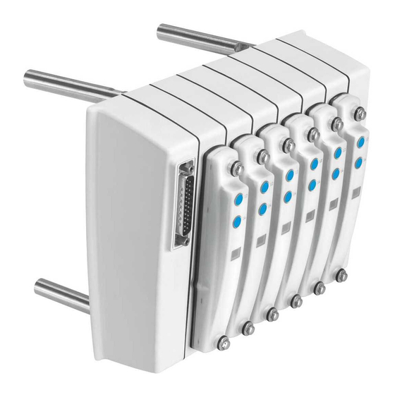
– supply ports (1), (3) and (5) – electronics module – working ports (2) and (4) Spacer bolt – valve with cover, optionally with manual override – electronics module Fig. 2.1 Main components of the valve terminal Festo – MPAC-VI-EN – 2017-12a – English... -
Page 11: Electrical Connection
1 … 32 VMPACEPL-IP… Tab. 2.3 I-port interface The valve terminal can be connected as follows: – to a device with an I-port interface – to an IO-Link master – to a connecting box CAPC-… Festo – MPAC-VI-EN – 2017-12a – English... -
Page 12: Description Of Components
Manifold sub-base with working ports (2), (4); supply ports (1), (3) and (5) VMPAC-AP-14-SP-2 and black electronics module for actuation by two solenoid coils 4) Manifold sub-base with drill holes for stud bolt mounting Tab. 2.4 Festo – MPAC-VI-EN – 2017-12a – English... -
Page 13: Valves
Monostable 3/2-way valve, normally open, external compressed air supply via port (2), pneumatic spring return Monostable 3/2-way valve, normally closed, external compressed air supply via port (4), pneumatic spring return Tab. 2.5 Identification codes for the valves Festo – MPAC-VI-EN – 2017-12a – English... -
Page 14: Check Valves
Cover with manual override 14 for valves with one solenoid coil VMPAC-VC-MO-14-1 Cover with manual override 12 and 14 for valves with two solenoid coils VMPAC-VC-MO-14-2 1) MO = manual override Tab. 2.6 Festo – MPAC-VI-EN – 2017-12a – English... - Page 15 Product overview Manifold sub-base Cover of the manifold sub-base Valve Cover plate for non-assigned valve position Mounting screws of the cover Fig. 2.4 Manifold sub-base with valve and cover Festo – MPAC-VI-EN – 2017-12a – English...
-
Page 16: Pneumatic Supply
Fig. 2.5 Internal/external pilot air supply Internal pilot air supply is only permitted if the operating pressure of the last pressure zone (next to the right end plate) is between 3 and 8 bar. Festo – MPAC-VI-EN – 2017-12a – English... -
Page 17: Exhaust Air
(L) of the right end plate. • Do not seal the port (L) on the right end plate under any circumstances. • Remove the pressure with ducts. • Do not use a check valve in the line. Festo – MPAC-VI-EN – 2017-12a – English... -
Page 18: Pressure Zone Separation
Pressure zone separation of the pilot duct (12/14) is not provided, since, with the valve terminal, the pilot air supply for the pilot control of the valves is supplied centrally via the right end plate. Festo – MPAC-VI-EN – 2017-12a – English... -
Page 19: Electrical Connection
– Valve terminal with IO-Link: Sub-D interface with 9 pins Sub-D connection on the valve side Sub-D connection on the connection side (front side, on top) (reverse side, underneath) Fig. 2.7 Electrical connection on the left end plate Festo – MPAC-VI-EN – 2017-12a – English... - Page 20 Supply port (1) (optional) Working port (2) Supply plate (optional) Working port (4) Sub-D connection/interface Pilot air supply port (12/14) (on the connection side here) Pilot exhaust port (82/84) Fig. 2.8 Pneumatic connections Festo – MPAC-VI-EN – 2017-12a – English...
-
Page 21: Display And Operating Components
Manual overrides (MOs), non-detenting (here on the valve side) Inspection window of the ident. code for Inspection window of the switching status the valve indications (yellow LEDs) Fig. 2.9 Display and operating components Festo – MPAC-VI-EN – 2017-12a – English... -
Page 22: Switching Status Indication Of The Valves
A manually actuated valve (by manual override) cannot be actuated electrically. Con versely, an electrically actuated valve cannot be activated using the mechanical manual override. The valve only returns to the rest position when both actuations are reset. Festo – MPAC-VI-EN – 2017-12a – English... -
Page 23: Mounting And Installation
• Only switch on the supply voltage when mounting and installation work are com pletely finished. Information for mounting the valve terminal can be found in the corresponding mounting instructions è www.festo.com/sp, enter search term: “Valve terminal MPAC-VI” or “Valve terminal MPAC-VI User Documentation”. Compressed air preparation 3.2.1... - Page 24 Incorrect supplemental oil and an oil rate in the compressed air that is too high will reduce the service life of the valve terminal. • Use Festo special oil OFSW-32 or the alternatives listed in the Festo catalogue (conforming to DIN 51524-HLP32, basic viscosity 32 CST at 40 °C).
-
Page 25: General Installation Instructions
• Optimise the pressurisation and ventilation capacity of the valve terminal, for example, by using larger diameter tubing or an additional compressed air supply via supply plates VMPAC-SP-O or manifold sub-bases VMPAC-AP-14-SP-…. • Possibly separate exhaust ducts through use of pressure zones (è Chapter 3.4.2). Festo – MPAC-VI-EN – 2017-12a – English... -
Page 26: Connecting The Valve Terminal
• The selector sleeve must be mounted in the right end plate. • Adapt the external pilot air supply to the operating pressure at which the valves are operated. Conversion between internal and external pilot air supply is described in chapter 7.4. Festo – MPAC-VI-EN – 2017-12a – English... -
Page 27: Pressure Zone Separation
8 supply plates. The following figure (è Fig. 3.1) shows the assignment of the supply and exhaust connections to the valves using a valve terminal with blocked channels (1), (3) and (5) as an example. Festo – MPAC-VI-EN – 2017-12a – English... - Page 28 Pressure zone 2 control of all pressure zones Pressure zone 3 Supply plate with port (1), (3) and (5) for supply to pressure zone 2 Fig. 3.1 Example: Valve terminal with 3 pressure zones Festo – MPAC-VI-EN – 2017-12a – English...
-
Page 29: Vacuum/Low-Pressure Operation
– The pilot air is supplied through the valve terminal. – The ports via which these valves are supplied with compressed air or vacuum and via which exhaust air is removed are shown in Tab. 3.3. Festo – MPAC-VI-EN – 2017-12a – English... -
Page 30: Connecting The Pneumatic Lines
• Mount the fitting or the silencer (è Tab. 3.4). Then lay the tubing lines. In the valve terminal, the pilot exhaust air on the right end plate must be exhausted through port (82/84). Festo – MPAC-VI-EN – 2017-12a – English... - Page 31 1) Depending on what you have ordered, the valve terminal may already be equipped with QS fittings. 2) Manifold sub-base with working ports 2, 4 and supply ports 1, 3 and 5 Tab. 3.4 Assignment of the ports Festo – MPAC-VI-EN – 2017-12a – English...
-
Page 32: Installation Of The Tubing Lines
2. Loosen the clamping screw (è Fig. 3.4, 1 ) of the fitting or, if necessary, press down the locking ring of the fitting 2, e.g. with the QSO releasing tool from Festo. 3. Remove the tubing from the fitting. -
Page 33: Common Pneumatic Lines
First valve terminal Central exhaust line (3/5) Common exhaust line (3/5) Second valve terminal Central pilot air exhaust tubing (82/84) Common pilot air exhaust line (82/84) Fig. 3.5 Common lines with check valves Festo – MPAC-VI-EN – 2017-12a – English... -
Page 34: Connecting The Electric Cables
2 – Less significant address for coils 14 – Higher-value address for coils 12 Tab. 3.5 Colour coding of the electronics modules – A supply plate does not occupy an address (blue electronics module) Festo – MPAC-VI-EN – 2017-12a – English... -
Page 35: Addressing Example
Manifold sub-bases with black electronics corresponding valve cover modules for valves with two solenoid coils and corresponding valve cover Fig. 3.6 Addressing example (top view) Festo – MPAC-VI-EN – 2017-12a – English... - Page 36 – Black electronics module – Addresses 11 and 12 are assigned. 0 V/24 V Connect 0 V with positive-switching control signals, 24 V with negative-switching control signals. Mixed operation is not permissible! Tab. 3.6 Addressing example Festo – MPAC-VI-EN – 2017-12a – English...
-
Page 37: Commissioning
This can cause damage to the machine or system and even injury to persons. • Operate the valve terminal with external pilot air (3 ... 8 bar). Branch the pilot air in front of the safety start-up valve (see Fig. 4.1). Festo – MPAC-VI-EN – 2017-12a – English... - Page 38 Slow After pressure rise at (1) Fast the safety start-up valve Branched upstream Slow Fast Before pressure rise Slow of the safety start-up valve at (1) Tab. 4.1 Effects of slow start-up pressurisation Festo – MPAC-VI-EN – 2017-12a – English...
-
Page 39: Testing The Valves And The Valve/Actuator Combination
• Reset the electric signal before actuating the manual override. Proceed as follows: 1. Switch on the compressed air supply. 2. Check the functionality and method of operation of each valve-actuator combination by actuating the relevant manual override (è Tab. 4.3). Festo – MPAC-VI-EN – 2017-12a – English... - Page 40 (not for bistable valves, code J). Tab. 4.3 Non-detenting actuation of the manual override 3. Switch off the compressed air supply after testing the valves. Festo – MPAC-VI-EN – 2017-12a – English...
-
Page 41: Diagnostics And Fault Clearance
– Operating voltage of the valves lies below the permitted tolerance range – Compressed air supply not OK – Pilot exhaust is blocked – Servicing required Tab. 5.1 Meaning of the LED display Festo – MPAC-VI-EN – 2017-12a – English... -
Page 42: Functional Impairments
• After switching on again, check the pilot pressure (if necessary, set as a factor of the operating pressure, see chapter 3) Tab. 5.2 Functional impairments of the pneumatic system Festo – MPAC-VI-EN – 2017-12a – English... -
Page 43: Operating Statuses Of The Pneumatic System
Slow switch-on after If control signals are present, the EMERGENCY OFF pilot air supply must have a pressure of 3 ... 8 bar immediately after being switched on Tab. 5.3 Pneumatic operating statuses Festo – MPAC-VI-EN – 2017-12a – English... -
Page 44: Cleaning And Maintenance
• Check seals for damage (to maintain IP degree of protection è Appendix A, Tab. A.4). • The contact surfaces must be dry and clean (sealing effect, avoidance of leakage and contact errors). Electrostatic sensitive components: Do not touch any electrical or electronic components. Festo – MPAC-VI-EN – 2017-12a – English... -
Page 45: Cleaning The Valve Terminal
• Do not hold a focused or rotating high-pressure spray on the valve terminal, especially on the seals. Material damage can occur from incorrect cleaning. Festo recommends maintaining the following para meters during cleaning: – Water pressure < 100 bar –... -
Page 46: Maintaining The Valve Terminal
• Use a screwdriver with a narrow blade to loosen the mounting screws of the valve or cover plate and remove it from the manifold sub-base (è Fig. 6.1, 2 ). Festo – MPAC-VI-EN – 2017-12a – English... - Page 47 6. Put the IP seal and the cover onto the manifold sub-base in the right position. 7. Tighten the screws for the cover at first so they are hand-tight and and then tighten firmly with a box spanner (tightening torque: 2.0 Nm (±10 %)). Festo – MPAC-VI-EN – 2017-12a – English...
- Page 48 Cleaning and maintenance Sealing disc Cord seal Mounting screws of the cover Manifold sub-base Cover of the manifold sub-base IP seal Valve Mounting screws of the valve Fig. 6.2 Mounting of valve or cover Festo – MPAC-VI-EN – 2017-12a – English...
-
Page 49: Conversion
In addition, there is another extension piece to enable subsequent extension of the valve terminal. Threaded sleeve Extension piece Tie rod screw Threaded rod (graduated lengths available) Sealing disc Fig. 7.1 Components of the tie rod system Festo – MPAC-VI-EN – 2017-12a – English... -
Page 50: Replacing Or Extending The Manifold Sub-Base, Supply Plate Or Replacing The Right End Plate
3. Loosen and remove the five screws of the tie rod on the right end plate using a size 6 ring spanner (è Fig. 7.2). The loosened manifold sub-bases are now only held in place by the electrical linking. Festo – MPAC-VI-EN – 2017-12a – English... - Page 51 7. Put a sealing disc onto each tie rod screw (è Fig. 7.2, 2 ). 8. Push the five tie rod screws through the drill holes of the right end plate into the threaded sleeves. Festo – MPAC-VI-EN – 2017-12a – English...
- Page 52 – 3rd step: 3.5 Nm ( ± 10 %) 10.Then check the torque on all five screws, as the torque on the screws can change during the tighten ing process. Fig. 7.4 Fittings in the right end plate Festo – MPAC-VI-EN – 2017-12a – English...
-
Page 53: Replacing Electronics Modules
3. Push the greased selector sleeve into the port 12/14 of the right end plate up to the stop. 4. Screw the fitting into the port 12/14. – Tightening torque, thread size G⅛": 2.0 Nm (±10 %) – Tightening torque, thread size NPCK G⅛": 2.0 Nm (±10 %) Festo – MPAC-VI-EN – 2017-12a – English... -
Page 54: Addition Of Pressure Zones
– In case of more than 2 pressure zones, one pneumatic supply plate each for the inside pressure zones (è Chapter 2.4.5). The procedure to convert pressure zones corresponds to the replacement or extension of components, as described in Chapter 7.2. Festo – MPAC-VI-EN – 2017-12a – English... - Page 55 – 2nd step: 2.0 Nm ( ± 10 %) – 3rd step: 3.5 Nm ( ± 10 %) 12.Then check the torque on all five screws, as the torque on the screws can change during the tighten ing process. Festo – MPAC-VI-EN – 2017-12a – English...
-
Page 56: Conversion Of The Outlet Orientation For The Electrical Connection
Tab. 7.3 Variants of the left end plate Dismounting 1. Loosen the electrical and pneumatic connections and then remove the valve terminal from its mounting surface (è Chapter 3.1). 2. Place the valve terminal on a flat working surface. Festo – MPAC-VI-EN – 2017-12a – English... - Page 57 3. Carry out the mounting steps in the reverse order to dismounting. 4. Mount the valve terminal to the mounting surface (è Chapter 2). 5. Then install the pneumatic and electrical connections (è Chapter 3). Festo – MPAC-VI-EN – 2017-12a – English...
-
Page 58: A Technical Appendix
End plates / manifold sub-base with mounting thread PA10T/X-GF50, stainless steel (not oxidising) Seals Elastomer, EPDM Tie rod Stainless steel (not oxidising) NPCK fittings (accessories) High alloy steel, stainless Tab. A.1 Technical data: Mechanical Festo – MPAC-VI-EN – 2017-12a – English... - Page 59 NPCK: G⅜" 12.0 (12/14), (82/84), (L) G⅛" NPCK: G⅛" (2), (4) G¼" NPCK: G¼" 1) No fittings with taper thread permitted! 2) For manifold sub-base VMPAC-AP-14-SP-… Tab. A.3 Tightening torques for fittings (accessories) Festo – MPAC-VI-EN – 2017-12a – English...
-
Page 60: Operating And Environmental Conditions
2) Corrosion resistance class 4 in accordance with Festo standard 940070-2: Components subject to particularly high corrosion stress. Externally visible parts with primarily functional surface requirements which are in direct contact with the surrounding industrial environment or media such as solvents and cleaning agents. -
Page 61: Pneumatics
Working area Fig. A.1 Diagram: Required pilot pressure related to the operating pressure with use of valves with ident. code B, E, DS, G, HS, J, KS, M, MS, NS, W and X Festo – MPAC-VI-EN – 2017-12a – English... - Page 62 Diagram: Required pilot pressure related to the operating pressure with use of valves with ident. code D, H, I, K and N The fittings of the pneumatic ports cause a reduction in the nominal flow rate of the valves. Festo – MPAC-VI-EN – 2017-12a – English...
- Page 63 H, K, N 2x 3/2-way 2x 3/2-way KS, NS 5/2-way, monostable M, MS 5/2-way, bistable valve 9/24 — 5/3-way, pressurized 16/26 5/3-way, exhausted 13/26 5/3-way, closed 13/26 Tab. A.7 Technical data: valve switching times Festo – MPAC-VI-EN – 2017-12a – English...
-
Page 64: Electrical Data
Current consumption (per solenoid coil, with LED) at 24 V DC Nominal pick-up current [mA] Pick-up duration [ms] Nominal current with current reduction [mA] Tab. A.10 Electrical data: valve terminal with I-Port interface/IO-Link Accessories è www.festo.com/catalogue Festo – MPAC-VI-EN – 2017-12a – English... -
Page 65: B Circuit Symbol
– Two monostable 2/2-way valves, normally closed – Pneumatic spring return 82/84 12/14 Ident. code: DS Function: – Two monostable 2/2-way valves, normally closed – Mechanical spring return 82/84 12/14 Tab. B.1 2/2-way valves Festo – MPAC-VI-EN – 2017-12a – English... - Page 66 1) Note: If this 2/2-way valve (ident. code I) is connected to other valves on the valve terminal, the 2/2-way valve is operated in a separate pressure zone with separate exhaust duct (5). Tab. B.2 2/2-way valves Festo – MPAC-VI-EN – 2017-12a – English...
- Page 67 – Two monostable 3/2-way valves, normally closed – Mechanical spring return 12/14 82/84 Ident. code: N Function: (14) (12) – Two monostable 3/2-way valves, normally open. – Pneumatic spring return 12/14 82/84 Tab. B.3 3/2-way valves Festo – MPAC-VI-EN – 2017-12a – English...
- Page 68 (12/14) Ident. code: M Function: – One monostable 5/2-way valve – Pneumatic spring return (12/14) Ident. code: MS Function: – One monostable 5/2-way valve – Mechanical spring return (12/14) Tab. B.5 5/2-way valves Festo – MPAC-VI-EN – 2017-12a – English...
- Page 69 (82/84) – Mid-position pressurized Ident. code: E Function: – 5/3-way valve – Mid-position exhausted (12/14) (82/84) Ident. code: G Function: – 5/3-way valve – Mid position closed (12/14) (82/84) Tab. B.6 5/3-way valves Festo – MPAC-VI-EN – 2017-12a – English...
-
Page 70: C Glossary
IO-Link and pneumatic supply ports – Outermost right plate with pneumatic supply ports Ident. code/ID code Identification code of a component in the Festo Configurator Manifold sub-base Plate with electrical and pneumatic linking, with working ports (2) and (4), for mounting a valve... -
Page 71: Index
....– Pressure range ..... . . Festo – MPAC-VI-EN – 2017-12a – English... - Page 72 ......Weights, Components ....Festo – MPAC-VI-EN – 2017-12a – English...
- Page 74 Copyright: Festo AG & Co. KG Ruiter Straße 82 73734 Esslingen Germany Phone: +49 711 347-0 Fax: +49 711 347-2144 Reproduction, distribution or sale of this document or communica E-mail: tion of its contents to others without express authorization is service_international@festo.com...
Need help?
Do you have a question about the MPAC-VI and is the answer not in the manual?
Questions and answers