Table of Contents
Advertisement
Quick Links
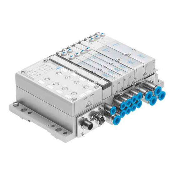
Valve terminal MPA−...
Electronic
description of
MPA−...
MPA electronic
module
Types:
− VMPA1−FB−...
− VMPA2−FB−...
− VMPA1−FB−...D2...
− VMPA2−FB−...D2...
MPA pressure
sensor
Type:
− VMPA−FB−PS−...
Proportional
pressure regulator
VPPM/MPA
Type:
− VPPM−6TA−...
Description
562 113
en 0804NH
[732 589]
Advertisement
Chapters
Table of Contents


Need help?
Do you have a question about the MPA Series and is the answer not in the manual?
Questions and answers