
Related Manuals for Extron electronics IP Link Series


Summary of Contents for Extron electronics IP Link Series
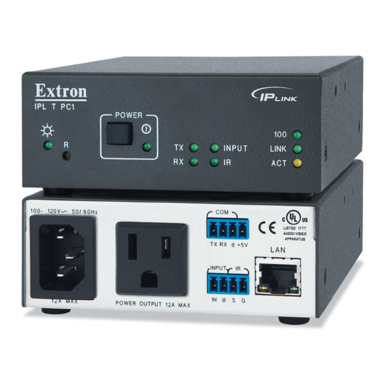
- Page 1 User Guide IP Link ® IPL T PC1 IPL T PC1i IP Link Power Control Interfaces 68-738-10 Rev. C 07 19...
- Page 2 Safety Instructions Safety Instructions • English Istruzioni di sicurezza • Italiano AVVERTENZA: Il simbolo, , se usato sul prodotto, serve ad WARNING This symbol, , when used on the product, is intended to avvertire l’utente della presenza di tensione non isolata pericolosa alert the user of the presence of uninsulated dangerous voltage within the all’interno del contenitore del prodotto che può...
- Page 3 Copyright © 2007-2019 Extron Electronics. All rights reserved. www.extron.com Trademarks All trademarks mentioned in this guide are the properties of their respective owners. The following registered trademarks ( ® ), registered service marks ( ), and trademarks ( ) are the property of RGB Systems, Inc. or Extron Electronics (see the current list of trademarks on the...
- Page 4 FCC Class A Notice This equipment has been tested and found to comply with the limits for a Class A digital device, pursuant to part 15 of the FCC rules. The Class A limits provide reasonable protection against harmful interference when the equipment is operated in a commercial environment.
- Page 5 Conventions Used in this Guide Notifications The following notifications are used in this guide: WARNING: Potential risk of severe injury or death. AVERTISSEMENT : Risque potentiel de blessure grave ou de mort. CAUTION: Risk of minor personal injury. ATTENTION : Risque de blessure mineure. ATTENTION: •...
-
Page 7: Table Of Contents
Contents Introduction ..........1 Using the IPL T PC1 Web Pages ....... 22 About this Guide ..........1 Viewing the System Status ......23 About the IPL T PC1..........1 Using the Configuration Pages ....... 24 Features .............. 1 Managing Files..........38 Application Diagram .......... - Page 8 IPL T PC1 • Contents viii...
-
Page 9: Introduction
Introduction This section provides an overview of the Extron IPL T PC1 and IPL T PC1i IP Link Power ® Control Interfaces, and describes their features. Topics covered in this section are: • About this Guide • About the IPL T PC1 Features •... - Page 10 Industry standard Ethernet protocols — The PC1 uses standard Ethernet and • TCP/IP communication protocols, including ARP (Address Resolution Protocol), DHCP (dynamic host configuration protocol), TCP/IP (Transmission Control Protocol/Internet Protocol), Telnet, and HTTP (HyperText Transfer Protocol). • Integral high-performance web server — The PC1 has a built-in web server with memory available for storing device drivers, GlobalViewer , and custom user web ®...
-
Page 11: Application Diagram
Application Diagram The following application diagram shows an example of how devices can be connected to the IPL T PC1 or the IPL T PC1i. Remote User Plasma Control and Display Administrator AC Power Monitoring Extron RS-232 IR Emitter TCP/IP Network Extron IN P... -
Page 12: Installation And Rear Panel
Installation and Rear Panel This section describes: • Installation Overview • Rear Panels Connecting Cables • Installation Overview To install and set up an IPL T PC1 interface: Disconnect power from the PC1 interface and the output device (plasma display, VCR, projector, and so forth). -
Page 13: Rear Panels
Rear Panels 100-120VAC 50/60Hz MAC ADDRESS ® LISTED 17TT AUDIO/VIDEO APARATUS INPUT POWER OUTPUT 12A MAX 12A MAX Figure 2. IPL T PC1 Rear Panel (120 VAC) 200-240VAC 50/60Hz MAC ADDRESS INPUT POWER OUTPUT 10A MAX 10A MAX Figure 3. IPL T PC1i Rear Panel (220 VAC) Power connector —... -
Page 14: Connecting Cables
Input contact closure port (see figure 2 figure 3 on the previous page) — Connect a contact closure device to pins 1 (IN, for input) and 2 ( , for ground) of this shared captive screw connector to enable the PC1 to detect a closed circuit between an input and ground and to trigger an event (see Wiring the Contact Input Port page 9). - Page 15 In figure 4, the Communication sheet link for a 3M-7340 display has been selected. Figure 4. Communication Sheet Access The communication sheet (a PDF file) opens. You can view, print, or download it. Wire your display device as described in its communication sheet. You can also access the Communication Sheets via the Global Configurator software (see the IPL T PC1 Setup Guide for information on using GC3.2).
-
Page 16: Wiring The Local Area Network (Lan) Port
Wiring the Local Area Network (LAN) Port Wire the connector as shown in the tables below. • For 10Base-T (10 Mbps) networks, use a Category 3 or better cable. • For 100Base-T (100 Mbps) networks, use a Category 5 cable. Use a straight-through cable to connect to a switch, hub, or router. -
Page 17: Wiring The Contact Input Port
Wiring the Contact Input Port The IPL T PC1 contact closure Input port can be connected to any device providing a closure to ground (closed = logic 1 and open = logic 0). The contact input is connected to 5 VDC via a 1k ohm pull-up resistor and must be wired with a ground. This allows the input to be tied to a device such as a motion detector, alarm, photo eye, and so forth. -
Page 18: Front Panel Features And Operation
Front Panel Features and Operation This section contains a description of the IPL T PC1 and IPL T PC1i front panel features and instructions for setting up the PC1 using the front panel. The following topics are discussed: • Front Panel Features •... -
Page 19: Setting Up The System Using The Front Panel
Power LED (see figure 8 on the previous page)— This green LED lights while the PC1 or PC1i interface is receiving power and is running. When the unit is being reset from the front panel, this LED blinks the appropriate number of times to indicate the reset mode the PC1 has entered (see Resetting page 12). -
Page 20: Resetting
Resetting Reset the unit by pressing the Reset button on the front panel. This button is recessed, and can be accessed with an Extron Tweeker or other small Phillips screwdriver. CAUTIONS: • Review the reset modes carefully. Use of the wrong reset mode may cause unintended loss of blinks memory programming or a unit reboot. -
Page 21: Mode 2
No LEDs blink to indicate the mode switch. If the switch to mode 2 is successful and serial port communication is enabled, the interface screen displays one of the following copyright messages: • (c) Copyright 2011, Extron Electronics, IPL T PC1, Vn.nn, 60-544-nn • (c) Copyright 2011, Extron Electronics, IPL T PC1i, Vn.nn, 60-544-nn... -
Page 22: Mode 4
Mode 4 Activation Hold the button in until the Power LED blinks twice Reset (approximately 6 seconds). Release it, then immediately press it again momentarily (for less than 1 second). The Power LED blinks four times in quick succession, confirming a mode 4 reset. NOTE: Nothing happens if the momentary press does not occur within 1 second. -
Page 23: Html Configuration And Control
HTML Configuration and Control This section describes the IPL T PC1 embedded web pages and provides instructions on accessing and using them to configure the PC1. Topics include: • Configuring the Hardware for Ethernet Control • Using the IPL T PC1 Web Pages •... - Page 24 If the PC1 has never been configured and is still set for factory defaults, skip to step 4. If not, perform a mode 4 system reset to restore the factory-set values (see Resetting page 12). CAUTION: The PC1 must be configured with the factory default IP address (192.168.254.254) before you execute the ARP command, as described below.
-
Page 25: Setting Up And Configuring The Pc1 Using A Web Browser
Figure 11. Ping Command on a Command Prompt Screen After verifying that the IP address change was successful, issue the command arp -d at the DOS prompt to remove the address from the computer ARP table. For example: arp -d 10.13.197.57 A space must separate from the hyphen ( Setting Up and Configuring the PC1 Using a Web Browser... -
Page 26: Setting Up The Computer For Ip Communication
Setting Up the Computer for IP Communication Follow these steps to set up communication between your computer and the PC1 using Windows 2000, Windows XP, or Windows 7. NOTE: The procedure and illustrations in this section are for Windows XP. For other Windows versions, the screens may appear slightly different. - Page 27 Figure 13. Internet Protocol (TCP/IP) Selected on Local Area Connection Properties Window Write down the current IP address and subnet mask of your computer below. You will need to restore these settings to the computer later. If the radio button has been selected, make a Obtain an IP address automatically note of that.
-
Page 28: Configuring The Ipl T Pc1 Using A Web Browser
Plug one end of a Category 5, 6, or 6E network crossover cable into the Ethernet (LAN) connector on the PC1 rear panel (see Wiring the Local Area Network (LAN) Port page 8 for information on wiring the RJ-45 LAN connector). Plug the other end of the Ethernet cable into the Ethernet port on the computer. - Page 29 Figure 15. System Settings Page with Default IP Address Enter the new IP address assigned for the PC1, the corresponding subnet mask, and gateway address, then click Submit IP, gateway, and subnet mask addresses follow standard naming and numbering conventions and protocol ( ).
-
Page 30: Using The Ipl T Pc1 Web Pages
Using the IPL T PC1 Web Pages The IPL T PC1 features an embedded web server, which includes factory set web pages. These pages can be replaced with user-designed files, but the default web pages provide many basic features for configuring, and controlling the PC1 via a web browser. This section provides an overview of the embedded web pages. -
Page 31: Viewing The System Status
Viewing the System Status web page, accessed by clicking the tab, provides information System Status Status on the current settings. Changes must be made via the Configuration web pages or SIS programming commands (see SIS Programming and Control on page 47). Personnel who have user access can view this page but cannot access the Configuration File... -
Page 32: Using The Configuration Pages
page displays information in the following categories: System Status • System Description — Includes product model, port and receptacle description, part number, firmware version, and the current date and time. • IP Settings — Displays the unit name, DHCP status, IP address, gateway address, subnet mask, and the MAC address. - Page 33 IP Settings The following settings are available in the section: IP Settings • — The default is the product name followed by the last six digits of Unit Name the MAC address. You can give the unit a new name (such as LightsOn&Off ) consisting of up to 24 alphanumeric characters including the BoardroomA-PC1...
- Page 34 • U. S. — Starts the second Sunday in March and ends the first Sunday in November. (Daylight saving time should be turned off in Hawaii, American Samoa, most equatorial regions, Guam, Puerto Rico, the U. S. Virgin Islands, eastern time zone portion of the state of Indiana, and the state of Arizona (excluding the Navajo Nation).
- Page 35 RS-232 port From the drop-boxes in the RS-232 port type section (left column), select the baud rate, data bits, parity, stop bits, and flow control for the PC1 serial COM port. Click to enter your selections. Submit If you click before submitting your selections, your entries are reset to the last Cancel saved parameters.
- Page 36 Using the IR Drivers page page lets you view the IR drivers that have been uploaded to the PC1 IR Drivers via the page (see Managing Files on page 38). You can also view File Management the commands contained within the IR driver, and cause the connected output device to perform (play) any of the listed commands.
- Page 37 Assigning passwords screen allows you to assign passwords to the administrator and user Passwords access levels. NOTE: The factory configured passwords for all accounts on this device have been set to the device serial number. In the event of a complete reset to factory defaults, the passwords convert to the default, which is no password.
- Page 38 In the , the , or both fields, delete Re-enter Admin Password Re-enter User Password the characters that are there, and press the < > to enter a space. Spacebar Click Submit NOTE: Deleting the administrator password also deletes the user password. Managing e-mail alerts If you have created scheduled events or monitoring tasks through the Global Configurator software, you may have e-mail alerts with a message corresponding to an event or task...
- Page 39 Entering e-mail addresses for alerts On the sidebar menu on the page, click Configuration Email Alerts On the page, click the button located to the right of the Email Alerts Edit Mail IP field. The page goes into Edit mode, and the button changes to Address Edit...
- Page 40 Upgrading firmware page lets you browse to locate and upload a new version of Firmware Upgrade firmware for your unit. The uploaded file must have the file extension .S19 NOTE: The PC1 uses the same firmware as the IPL T PC1. However, it does not accept other firmware files, such as the files for the IP Link S Series.
- Page 41 Click to open a window. Browse Choose file Figure 25. Firmware File Selected on the Choose File Window In the window, locate the new firmware version file on your computer Choose file and double-click it. (Firmware files must have the extension .S19.) By default, this file is placed at: c: \Program Files\Extron\Firmware\IPL_T_PC1\pcsVx.xx.S19 The firmware file name and path are displayed in the...
- Page 42 Scheduling page accessed from the screen lets you schedule when Schedule Configuration power to the receptacle turns on and off. You can also schedule lock mode, specifying when the PC1 front panel will be locked. Clicking the button at the bottom Clear Schedule of the screen deletes all schedules.
- Page 43 Scheduling output receptacle power To schedule power on and off to the output receptacle: In the section, click to select the power setting that you want Receptacle 1 to schedule for the week. A section appears above the Set Schedule For Scheduling section, displaying the receptacle number (always , for PC1/PC1i), the power selection...
- Page 44 Scheduling front panel lockout (executive mode) In the section, click to select the lock mode setting that Executive Mode you want to schedule. A section appears above the Set Schedule For Scheduling section, displaying the current status of ); menus from Executive Mode which to select the hour, minutes, and am or pm;...
- Page 45 Scheduling by day of the week You can also select a day of the week and schedule all power and executive mode time settings for that day at one time: Click on a day of the week at the top of a column in the scheduling Receptacle 1 table.
-
Page 46: Managing Files
Changing an individual setting Follow this procedure if you want to change only one setting on the scheduling table, either for powering on or off, or for executive mode. In the scheduling table, click on the time displayed or Receptacle Executive Mode the “-”... - Page 47 Figure 31. File Management Screen with Three Files Uploaded Click ). While the file is uploading, the button label Upload File Upload File changes to Uploading... When the uploading is complete, the uploaded file name appears in the column ( Files with a time stamp showing GMT time, and the button returns to its original state.
-
Page 48: Custom Web Pages
Custom Web Pages On the IPL T PC1, custom web pages are supported. You can determine the layout and appearance of the pages displayed on your screen. Server side includes (SSIs) enable you to obtain information from the unit and display the information on web pages. Query strings allow you to send information and commands to the unit to change its configuration or provide you with feedback (see Query strings... - Page 49 Code example The following figure shows a practical use for both SSIs and query strings. In this example, the HTML source code contains three SSI commands. <html> <head><title>Example 1</title></head> <h2 b>HTML Example #1</h2 b> <body> The following lines demonstrate how to read status from the IPLink Product: IPLink Product Name: <b><!--#echo var="1I"--></b>...
- Page 50 URL encoding URL (Universal Resource Locator) encoding is the method of using ASCII hexadecimal characters to display specific characters in a URL. It is used for several reasons. On some operating systems, certain characters are unsafe or not available, and others are reserved by the HTML or URL specification.
-
Page 51: Accessing And Using Telnet (Port 23)
Character Hexadecimal Decimal Left brace Right brace Vertical bar or pipe Back slash Caret Tilde Left bracket Right bracket Grave accent Accessing and Using Telnet (Port 23) Telnet, short for Telecommunications Network, provides a way for you to connect to a computer or server (in this case, the PC1 interface) on a network. - Page 52 At the prompt, enter the IP address of the PC1 unit (the default IP address is < to > . If the address was changed in the setup or configuration process, 192.168.254.254 use the new address). Telnet defaults to port 23. POWER Receptacle Power Button...
-
Page 53: Troubleshooting
Troubleshooting Turn on the equipment in the following order: The PC1 power control interface The power receptacles on the PC1 The connected output device on the AC receptacle. If the output AV device cannot be powered on, check the following: Power Connections Make sure that the output receptacle is receiving power. -
Page 54: Global Configurator Software
If a connection was not made, the following response appears: Figure 41. Response to an Unsuccessful Ping Command If you get a response indicating that the ping was unsuccessful: Make sure your unit is using the appropriate subnet mask (check with your system administrator). -
Page 55: Sis Programming And Control
When a local event such as a front panel selection or adjustment takes place, the PC1 responds by sending a message to the host. No response is required from the host. The following PC1-initiated messages are sent (underlined): © Copyright 2011, Extron Electronics, IPL T PC1[i], Vn.nn, 60-544-nn] Www, DD Mmm 2011... -
Page 56: Password Information
Password Information prompt is displayed only if there is a password defined in the unit. It Password: requires a password (administrator level or user level) followed by a carriage return. The prompt is repeated if the correct password is not entered. NOTE: The factory configured passwords for all accounts on this device have been set to the device serial number. -
Page 57: Using The Command And Response Table
Using the Command and Response Table The PC1 can be controlled via either a Telnet (port 23) connection or a web browser (port 80) connection. The ASCII commands listed in the tables perform the same functions, but they are encoded differently to accommodate the requirements of each port (Telnet or web browser). -
Page 58: Symbol Definitions
Symbol Definitions CR/LF (carriage return + line feed) (hex 0D 0A) Soft carriage return (no line feed, hex 0D) (For web browser commands, use the | [pipe] character instead of the soft return.) Pipe (vertical bar) character • Space superscript indicates commands that give an E24 (privilege violation) message if you are not logged in at the administrator level. - Page 59 For verbose response mode: 0 = clear or none (default), 1 = verbose mode, 2 = tagged responses for queries, 3 = verbose mode and tagged responses for queries NOTE: If tagged responses are enabled, all read commands return the constant string plus the data, like setting the value does.
- Page 60 = Default name: a combination of the model name and the last three pairs of the interface MAC address (for example: IPL-T-PC1-00-02-3D). = Connection security level: 11 = user, 12 = administrator = ASCII digits representing the numeric value of the data element read from the event buffer (leading zeros are suppressed).
-
Page 61: Command And Response Table For Sis Commands
Command and Response Table for SIS Commands ASCII (Telnet) URL Encoded (web) Response Command (Host to Switcher) (Host to Switcher) (Switcher to Host) Power Receptacle Control / Current Sense Turn receptacle power on 1*1PC W 1 %2A 1PC Cpn 01 •... - Page 62 ASCII (Telnet) URL Encoded (web) Response Command (Host to Switcher) (Host to Switcher) (Switcher to Host) Web Browser-specific Commands Read response from last URL cmd W UB Response from command NOTE: An asterisk (*) after a version number indicates the version currently running. Question marks (?.??) indicate that only the factory firmware version is loaded.
- Page 63 ASCII (Telnet) URL Encoded (web) Response Command (Host to Switcher) (Host to Switcher) (Switcher to Host) E-mail Commands Configure e-mail events (mailbox) E X4% X4& X4& X4& ] Example: 5,jdoe@extron.com,7.emlCR W5%2Cjdoe%40extron%2Ecom%2C7%2EemlCR| Ipr5,jdoe@extron.com,7.eml View e-mail events (mailbox) E X4% X4& ] Send e-mail events (file named in E X4% X4^ ]...
- Page 64 ASCII (Telnet) URL Encoded (web) Response Command (Host to Switcher) (Host to Switcher) (Switcher to Host) IP Setup Commands (continued) Set GMT offset E X# X# ] View GMT offset W CZ X# ] Set daylight savings time E X3$ X3$ ] View daylight savings time X3$ ]...
- Page 65 ASCII (Telnet) URL Encoded (web) Response Command (Host to Switcher) (Host to Switcher) (Switcher to Host) IP Setup Commands (continued) Set broadcast port and MAC port number* address W port number* Bpt port number* X1* ] View broadcast port and MAC W PB| port number* X1* ]...
- Page 66 ASCII (Telnet) URL Encoded (web) Response Command (Host to Switcher) (Host to Switcher) (Switcher to Host) Remapping Port Designations NOTE: Duplicate port number assignments are not permitted, that is, Telnet and web cannot be the same. Entering duplicate port assignments results in an E13 (invalid parameter) error message. Set Telnet port map port number MT W port number MT...
- Page 67 ASCII (Telnet) URL Encoded (web) Response Command (Host to Switcher) (Host to Switcher) (Switcher to Host) File Commands Erase user-supplied web page or filename EF W filename EF • filename file 24, 28 Erase current directory and its W %2F EF files 24, 28 Erase current directory and its...
- Page 68 ASCII (Telnet) URL Encoded (web) Response Command (Host to Switcher) (Host to Switcher) (Switcher to Host) Reset (Zap) and Erase Commands NOTE: None of the following zap commands (ZFFF, ZXXX, ZY, or ZQQQ) reset the AC power receptacle. Power remains in its current state.
-
Page 69: Reference Material - Mounting The Ipl T Pc1
Reference Material — Mounting the IPL T PC1 The IPL T PC1 can be set on a table, mounted on a rack shelf, or mounted under furniture such as a desk, podium, or tabletop. Tabletop Use Rack Mounting Tabletop Use Four self-adhesive rubber feet are included with the PC1. -
Page 70: Under-Desk Mounting
Rack Mounting Procedure To mount the PC1 on a rack shelf: If rubber feet have been installed on the bottom of the unit, remove them. Mount the PC1 on the rack shelf, using two 4-40 x 3/16 inch screws in opposite (diagonal) corners of the unit to secure it to the shelf (see figure 43 on the next page). - Page 71 Slide the unit slightly forward or back, then tighten all four screws to secure it in place. Figure 44. Mounting the IPL T PC1 Under Furniture IPL T PC1 • Reference Material — Mounting the IPL T PC1...
- Page 72 Extron Electronics makes no further warranties either expressed or implied with respect to the product and its quality, performance, merchantability, or fitness for any particular use. In no event will Extron Electronics be liable for direct, indirect, or consequential damages resulting from any defect in this product even if Extron Electronics has been advised of such damage.
Need help?
Do you have a question about the IP Link Series and is the answer not in the manual?
Questions and answers